electric power transformer engineering
Bạn đang xem bản rút gọn của tài liệu. Xem và tải ngay bản đầy đủ của tài liệu tại đây (11.19 MB, 481 trang )
ELECTRIC
POWER
TR ANSFORMER
ENGINEERING
© 2004 by CRC Press LLC
© 2004 by CRC Press LLC
This book contains information obtained from authentic and highly regarded sources. Reprinted material is quoted with
permission, and sources are indicated. A wide variety of references are listed. Reasonable efforts have been made to publish
reliable data and information, but the author and the publisher cannot assume responsibility for the validity of all materials
or for the consequences of their use.
Neither this book nor any part may be reproduced or transmitted in any form or by any means, electronic or mechanical,
including photocopying, microfilming, and recording, or by any information storage or retrieval system, without prior
permission in writing from the publisher.
All rights reserved. Authorization to photocopy items for internal or personal use, or the personal or internal use of specific
clients, may be granted by CRC Press LLC, provided that $1.50 per page photocopied is paid directly to Copyright Clearance
Center, 222 Rosewood Drive, Danvers, MA 01923 USA. The fee code for users of the Transactional Reporting Service is
ISBN 0-8493-1704-5/04/$0.00+$1.50. The fee is subject to change without notice. For organizations that have been granted
a photocopy license by the CCC, a separate system of payment has been arranged.
The consent of CRC Press LLC does not extend to copying for general distribution, for promotion, for creating new works,
or for resale. Specific permission must be obtained in writing from CRC Press LLC for such copying.
Direct all inquiries to CRC Press LLC, 2000 N.W. Corporate Blvd., Boca Raton, Florida 33431.
Trademark Notice: Product or corporate names may be trademarks or registered trademarks, and are used only for
identification and explanation, without intent to infringe.
With regard to material reprinted from IEEE publications:
The IEEE disclaims any responsibility or liability resulting from the placement and use in the described manner.
Visit the CRC Press Web site at www.crcpress.com
© 2004 by CRC Press LLC
No claim to original U.S. Government works
International Standard Book Number 0-8493-1704-5
Library of Congress Card Number 2003046134
Printed in the United States of America 1 2 3 4 5 6 7 8 9 0
Printed on acid-free paper
Library of Congress Cataloging-in-Publication Data
Electric power transformer engineering / edited by James H. Harlow.
p. cm. — (The Electric Power Engineering Series ; 9)
Includes bibliographical references and index.
ISBN 0-8493-1704-5 (alk. paper)
1. Electric transformers. I. Harlow, James H. II. title. III. Series.
TK2551.E65 2004
621.31d4—dc21 2003046134
© 2004 by CRC Press LLC
Preface
Transformer engineering is one of the earliest sciences within the field of electric power engineering, and
power is the earliest discipline within the field of electrical engineering. To some, this means that
transformer technology is a fully mature and staid industry, with little opportunity for innovation or
ingenuity by those practicing in the field.
Of course, we in the industry find that premise to be erroneous. One need only scan the technical
literature to recognize that leading-edge suppliers, users, and academics involved with power transformers
are continually reporting novelties and advancements that would have been totally insensible to engineers
of even the recent past. I contend that there are three basic levels of understanding, any of which may
be appropriate for persons engaged with transformers in the electric power industry. Depending on day-
to-day involvement, the individual’s posture in the field can be described as:
• Curious — those with only peripheral involvement with transformers, or a nonprofessional lacking
relevant academic background or any particular need to delve into the intricacies of the science
• Professional — an engineer or senior-level technical person who has made a career around electric
power transformers, probably including other heavy electric-power apparatus and the associated
power-system transmission and distribution operations
• Expert — those highly trained in the field (either practically or analytically) to the extent that
they are recognized in the industry as experts. These are the people who are studying and pub-
lishing the innovations that continue to prove that the field is nowhere near reaching a techno-
logical culmination.
So, to whom is this book directed? It will truly be of use to any of those described in the previous
three categories.
The
curious person will find the material needed to advance toward the level of professional. This
reader can use the book to obtain a deeper understanding of many topics.
The
professional, deeply involved with the overall subject matter of this book, may smugly grin with
the self-satisfying attitude of, “I know all that!” This person, like myself, must recognize that there are
many transformer topics. There is always room to learn. We believe that this book can also be a valuable
resource to professionals.
The
expert may be so immersed in one or a few very narrow specialties within the field that he also
may benefit greatly from the knowledge imparted in the peripheral specialties.
The book is divided into three fundamental groupings: The first stand-alone chapter is devoted to
Theory and Principles. The second chapter, Equipment Types, contains nine sections that individually treat
major transformer types. The third chapter, which contains 14 sections, addresses Ancillary Topics asso-
ciated with power transformers. Anyone with an interest in transformers will find a great deal of useful
information.
© 2004 by CRC Press LLC
I wish to recognize the interest of CRC Press and the personnel who have encouraged and supported
the preparation of this book. Most notable in this regard are Nora Konopka, Helena Redshaw, and
Gail Renard. I also want to acknowledge Professor Leo Grigsby of Auburn University for selecting me to
edit the “Transformer” portion of his The Electric Power Engineering Handbook (CRC Press, 2001), which
forms the basis of this handbook. Indeed, this handbook is derived from that earlier work, with the
addition of four wholly new chapters and the very significant expansion and updating of much of the
other earlier work. But most of all, appreciation is extended to each writer of the 24 sections that
comprise this handbook. The authors’ diligence, devotion, and expertise will be evident to the reader.
James H. Harlow
Editor
© 2004 by CRC Press LLC
Editor
James H. Harlow has been self-employed as a principal of Harlow Engineering Associates, consulting to
the electric power industry, since 1996. Before that, he had 34 years of industry experience with Siemens
Energy and Automation (and its predecessor Allis-Chalmers Co.) and Beckwith Electric Co., where he
was engaged in engineering design and management. While at these firms, he managed groundbreaking
projects that blended electronics into power transformer applications. Two such projects (employing
microprocessors) led to the introduction of the first intelligent-electronic-device control product used
in quantity in utility substations and a power-thyristor application for load tap changing in a step-voltage
regulator.
Harlow received the BSEE degree from Lafayette College, an MBA (statistics) from Jacksonville State
University, and an MS (electric power) from Mississippi State University. He joined the PES Transformers
Committee in 1982, serving as chair of a working group and a subcommittee before becoming an officer
and assuming the chairmanship of the PES Transformers Committee for 1994–95. During this period,
he served on the IEEE delegation to the ANSI C57 Main Committee (Transformers). His continued
service to IEEE led to a position as chair of the PES Technical Council, the assemblage of leaders of the
17 technical committees that comprise the IEEE Power Engineering Society. He recently completed a
2-year term as PES vice president of technical activities.
Harlow has authored more than 30 technical articles and papers, most recently serving as editor of
the transformer section of
The Electric Power Engineering Handbook, CRC Press, 2001. His editorial
contribution within this handbook includes the section on his specialty, LTC Control and Transformer
Paralleling. A holder of five U.S. patents, Harlow is a registered professional engineer and a senior member
of IEEE.
© 2004 by CRC Press LLC
Contributors
Dennis Allan
MerlinDesign
Stafford, England
Hector J. Altuve
Schweitzer Engineering
Laboratories, Ltd.
Monterrey, Mexico
Gabriel Benmouyal
Schweitzer Engineering
Laboratories, Ltd.
Longueuil, Quebec, Canada
Behdad Biglar
Trench Ltd.
Scarborough, Ontario,
Canada
Wallace Binder
WBBinder
Consultant
New Castle, Pennsylvania
Antonio Castanheira
Trench Brasil Ltda.
Contegem, Minas Gelais, Brazil
Craig A. Colopy
Cooper Power Systems
Waukesha, Wisconsin
Robert C. Degeneff
Rensselaer Polytechnic Institute
Troy, New York
Scott H. Digby
Waukesha Electric Systems
Goldsboro, North Carolina
Dieter Dohnal
Maschinenfabrik Reinhausen
GmbH
Regensburg, Germany
Douglas Dorr
EPRI PEAC Corporation
Knoxville, Tennessee
Richard F. Dudley
Trench Ltd.
Scarborough, Ontario, Canada
Ralph Ferraro
Ferraro, Oliver & Associates, Inc.
Knoxville, Tennessee
Dudley L. Galloway
Galloway Transformer
Technology LLC
Jefferson City, Missouri
Anish Gaikwad
EPRI PEAC Corporation
Knoxville, Tennessee
Armando Guzmán
Schweitzer Engineering
Laboratories, Ltd.
Pullman, Washington
James H. Harlow
Harlow Engineering Associates
Mentone, Alabama
Ted Haupert
TJ/H2b Analytical Services
Sacramento, California
William R. Henning
Waukesha Electric Systems
Waukesha, Wisconsin
Philip J. Hopkinson
HVOLT, Inc.
Charlotte, North Carolina
Sheldon P. Kennedy
Niagara Transformer
Corporation
Buffalo, New York
Andre Lux
KEMA T&D Consulting
Raleigh, North Carolina
Arindam Maitra
EPRI PEAC Corporation
Knoxville, Tennessee
Arshad Mansoor
EPRI PEAC Corporation
Knoxville, Tennessee
© 2004 by CRC Press LLC
Shirish P. Mehta
Waukesha Electric Systems
Waukesha, Wisconsin
Harold Moore
H. Moore & Associates
Niceville, Florida
Dan Mulkey
Pacific Gas & Electric Co.
Petaluma, California
Randy Mullikin
Kuhlman Electric Corp.
Versailles, Kentucky
Alan Oswalt
Consultant
Big Bend, Wisconsin
Paulette A. Payne
Potomac Electric Power
Company (PEPCO)
Washington, DC
Dan D. Perco
Perco Transformer Engineering
Stoney Creek, Ontario, Canada
Gustav Preininger
Consultant
Graz, Austria
Jeewan Puri
Transformer Solutions
Matthews, North Carolina
Leo J. Savio
ADAPT Corporation
Kennett Square, Pennsylvania
Michael Sharp
Trench Ltd.
Scarborough, Ontario, Canada
H. Jin Sim
Waukesha Electric Systems
Goldsboro, North Carolina
Robert F. Tillman, Jr.
Alabama Power Company
Birmingham, Alabama
Loren B. Wagenaar
America Electric Power
Pickerington, Ohio
© 2004 by CRC Press LLC
Contents
Chapter 1 Theory and Principles Dennis Allan and Harold Moore
Chapter 2 Equipment Types
2.1 Power Transformers H. Jin Sim and Scott H. Digby
2.2 Distribution Transformers Dudley L. Galloway and Dan Mulkey
2.3Phase-Shifting Transformers Gustav Preininger
2.4 Rectifier Transformers Sheldon P. Kennedy
2.5Dry-Type Transformers Paulette A. Payne
2.6 Instrument Transformers Randy Mullikin
2.7Step-Voltage Regulators Craig A. Colopy
2.8 Constant-Voltage Transformers Arindam Maitra, Anish Gaikwad,
Ralph Ferraro, Douglas Dorr, and Arshad Mansoor
2.9Reactors Richard F. Dudley, Michael Sharp, Antonio Castanheira,
and Behdad Biglar
Chapter 3
Ancillary Topics
3.1 Insulating Media Leo J. Savio and Ted Haupert
3.2Electrical Bushings Loren B. Wagenaar
3.3Load Tap Changers Dieter Dohnal
3.4Loading and Thermal Performance Robert F. Tillman, Jr.
3.5Transformer Connections Dan D. Perco
3.6Transformer Testing Shirish P. Mehta and William R. Henning
3.7 Load-Tap-Change Control and Transformer Paralleling
James H. Harlow
3.8Power Transformer Protection Armando Guzmán, Hector J. Altuve,
and Gabriel Benmouyal
3.9 Causes and Effects of Transformer Sound Levels Jeewan Puri
3.10Transient-Voltage ResponseRobert C. Degeneff
3.11 Transformer Installation and MaintenanceAlan Oswalt
3.12Problem and Failure Investigation Wallace Binder
and Harold Moore
3.13On-Line Monitoring of Liquid-Immersed Transformers Andre Lux
3.14U.S. Power Transformer Equipment Standards and Processes
Philip J. Hopkinson
© 2004 by CRC Press LLC
1
Theory and Principles
1.1Air Core Transformer
1.2Iron or Steel Core Transformer
1.3Equivalent Circuit of an Iron-Core Transformer
1.4The Practical Transformer
Magnetic Circuit • Leakage Reactance • Load Losses • Short-
Circuit Forces • Thermal Considerations • Voltage
Considerations
References
Transformers are devices that transfer energy from one circuit to another by means of a common magnetic
field. In all cases except autotransformers, there is no direct electrical connection from one circuit to the
other.
When an alternating current flows in a conductor, a magnetic field exists around the conductor,
asillustrated in Figure 1.1. If another conductor is placed in the field created by the first conductor such
that the flux lines link the second conductor, as shown in Figure 1.2, then a voltage is induced into the
secondconductor. The use of a magnetic field from one coil to induce a voltage into a second coil is the
principle on which transformer theory and application is based.
1.1Air Core Transformer
Some small transformers for low-power applications are constructed with air between the two coils. Such
transformers are inefficient because the percentage of the flux from the first coil that links the second
coil is small. The voltage induced in the second coil is determined as follows.
E = N d
J/dt 10
8
(1.1)
where N is the number of turns in the coil, dJ/dt is the time rate of change of fluxlinking the coil, and J
is the flux in lines.
Ata time when the applied voltage to the coil is E and the flux linking the coils is
Jlines, the
instantaneous voltage of the supply is:
e = 2 E cos [t = N dJ/dt 10
8
(1.2)
dJ/dt = (2 cos [t 10
8
)/N(1.3)
The maximum value of Jis given by:
J= (2 E 10
8
)/(2TfN)(1.4)
Using the MKS (metric) system, where Jis the flux in webers,
Dennis Allan
MerlinDesign
Harold Moore
H. Moore and Associates
© 2004 by CRC Press LLC
E = N dJ/dt(1.5)
and
J= (2E)/(2TfN)(1.6)
Since the amount of flux Jlinking the second coil is a small percentage of the flux from the first coil,
the voltage induced into the second coil is small. The number of turns can be increased to increase the voltage
output, but this will increase costs.The need then is to increase the amount of flux from the first coil
that links the second coil.
1.2Iron or Steel Core Transformer
The ability of iron or steel to carry magnetic flux is much greater than air. This ability to carry flux is
called permeability. Modern electrical steels have permeabilities in the order of 1500 compared with 1.0 for
air. This means that the ability of a steel core to carry magnetic flux is 1500 times that of air. Steel cores
wereused in power transformers when alternating current circuits for distribution of electrical energy
werefirst introduced. When two coils are applied on a steel core, as illustrated in Figure 1.3, almost
100% of the flux from coil 1 circulates in the iron core so that the voltage induced into coil 2 is equal
tothe coil 1 voltage if the number of turns in the two coils are equal.
Continuing in the MKS system, the fundamental relationship between magnetic flux density (B) and
magnetic field intensity (H) is:
FIGURE 1.1 Magnetic field around conductor.
FIGURE 1.2 Magnetic field around conductor induces voltage in second conductor.
Current carrying
conductor
Flux lines
Flux lines
Second conductor
in flux lines
© 2004 by CRC Press LLC
B = Q
0
H (1.7)
where Q
0
is the permeability of free space | 4Tv10
–7
Wb A
–1
m
–1
.
Replacing B by J/A and H by (I N)/d, where
J = core flux in lines
N = number of turns in the coil
I = maximum current in amperes
A = core cross-section area
the relationship can be rewritten as:
J = (Q N A I)/d (1.8)
where
d = mean length of the coil in meters
A = area of the core in square meters
Then, the equation for the flux in the steel core is:
J = (Q
0
Q
r
N A I)/d (1.9)
whereQ
r
= relative permeability of steel } 1500.
Since the permeability of the steel is very high compared with air, all of the flux can be considered as
flowing in the steel and is essentially of equal magnitude in all parts of the core. The equation for the
flux in the core can be written as follows:
J = 0.225 E/fN (1.10)
where
E = applied alternating voltage
f = frequency in hertz
N = number of turns in the winding
In transformer design, it is useful to use flux density, and Equation 1.10 can be rewritten as:
B = J/A = 0.225 E/(f A N) (1.11)
where B = flux density in tesla (webers/square meter).
FIGURE 1.3 Two coils applied on a steel core.
Flux in core
Steel core
Second winding
Exciting winding
© 2004 by CRC Press LLC
1.3 Equivalent Circuit of an Iron-Core Transformer
When voltage is applied to the exciting or primary winding of the transformer, a magnetizing current
flows in the primary winding. This current produces the flux in the core. The flow of flux in magnetic
circuits is analogous to the flow of current in electrical circuits.
When flux flows in the steel core, losses occur in the steel. There are two components of this loss, which
are termed “eddy” and “hysteresis” losses. An explanation of these losses would require a full chapter.
For the purpose of this text, it can be stated that the hysteresis loss is caused by the cyclic reversal of
flux in the magnetic circuit and can be reduced by metallurgical control of the steel. Eddy loss is
caused by eddy currents circulating within the steel induced by the flow of magnetic flux normal to the
width of the core, and it can be controlled by reducing the thickness of the steel lamination or by applying
a thin insulating coating.
Eddy loss can be expressed as follows:
W = K[w]
2
[B]
2
watts (1.12)
where
K = constant
w = width of the core lamination material normal to the flux
B = flux density
If a solid core were used in a power transformer, the losses would be very high and the temperature
would be excessive. For this reason, cores are laminated from very thin sheets, such as 0.23 mm and 0.28
mm, to reduce the thickness of the individual sheets of steel normal to the flux and thereby reducing the
losses. Each sheet is coated with a very thin material to prevent shorts between the laminations. Improve-
ments made in electrical steels over the past 50 years have been the major contributor to smaller and
more efficient transformers. Some of the more dramatic improvements include:
• Development of cold-rolled grain-oriented (CGO) electrical steels in the mid 1940s
• Introduction of thin coatings with good mechanical properties
• Improved chemistry of the steels, e.g., Hi-B steels
• Further improvement in the orientation of the grains
• Introduction of laser-scribed and plasma-irradiated steels
• Continued reduction in the thickness of the laminations to reduce the eddy-loss component of
the core loss
• Introduction of amorphous ribbon (with no crystalline structure) — manufactured using rapid-
cooling technology — for use with distribution and small power transformers
The combination of these improvements has resulted in electrical steels having less than 40% of the no-
load loss and 30% of the exciting (magnetizing) current that was possible in the late 1940s.
The effect of the cold-rolling process on the grain formation is to align magnetic domains in the
direction of rolling so that the magnetic properties in the rolling direction are far superior to those in
other directions. A heat-resistant insulation coating is applied by thermochemical treatment to both sides
of the steel during the final stage of processing. The coating is approximately 1-
Qm thick and has only
a marginal effect on the stacking factor. Traditionally, a thin coat of varnish had been applied by the
transformer manufacturer after completion of cutting and punching operations. However, improvements
in the quality and adherence of the steel manufacturers’ coating and in the cutting tools available have
eliminated the need for the second coating, and its use has been discontinued.
Guaranteed values of real power loss (in watts per kilogram) and apparent power loss (in volt-amperes
per kilogram) apply to magnetization at 0º to the direction of rolling. Both real and apparent power loss
increase significantly (by a factor of three or more) when CGO is magnetized at an angle to the direction
of rolling. Under these circumstances, manufacturers’ guarantees do not apply, and the transformer
© 2004 by CRC Press LLC
manufacturer must ensure that a minimum amount of core material is subject to cross-magnetization,
i.e., where the flow of magnetic flux is normal to the rolling direction. The aim is to minimize the total
coreloss and (equally importantly) to ensure that the core temperature in the area is maintained within
safe limits. CGO strip cores operate at nominal flux densities of 1.6 to 1.8 tesla (T). This value compares
with 1.35 T used for hot-rolled steel, and it is the principal reason for the remarkable improvement
achieved in the 1950s in transformer output per unit of active material. CGO steel is produced in two
magnetic qualities (each having two subgrades) and up to four thicknesses (0.23, 0.27, 0.30, and 0.35
mm), giving a choice of eight different specific loss values. In addition, the designer can consider using
domain-controlled Hi-B steel of higher quality, available in three thicknesses (0.23, 0.27, and 0.3 mm).
The different materials are identified by code names:
•CGO material with a thickness of 0.3 mm and a loss of 1.3 W/kg at 1.7 T and 50 Hz, or 1.72 W/
kg at 1.7 T and 60 Hz, is known as M097–30N.
•Hi-B material with a thickness of 0.27 mm and a loss of 0.98 W/kg at 1.7T and 50 Hz, or 1.3 W/
kg at 1.7 T and 60 Hz, is known as M103–27P.
•Domain-controlled Hi-B material with a thickness of 0.23 mm and a loss of 0.92 W/kg at 1.7T
and 50 Hz, or 1.2 W/kg at 1.7 T and 60 Hz, is known as 23ZDKH.
The Japanese-grade ZDKH core steel is subjected to laser irradiation to refine the magnetic domains
near to the surface. This process considerably reduces the anomalous eddy-current loss, but the lamina-
tions must not be annealed after cutting. An alternative route to domain control of the steel is to use
plasma irradiation, whereby the laminations can be annealed after cutting.
The decision on which grade to use to meet a particular design requirement depends on the charac-
teristics required in respect of impedance and losses and, particularly, on the cash value that the purchaser
has assigned to core loss (the capitalized value of the iron loss). The higher labor cost involved in using
the thinner materials is another factor to be considered.
No-load and load losses are often specified as target values by the user, or they may be evaluated by the
“capitalization” of losses. A purchaser who receives tenders from prospective suppliers must evaluate the
tenders to determine the “best” offer. The evaluation process is based on technical, strategic, and economic
factors, but if losses are to be capitalized, the purchaser will always evaluate the “total cost of ownership,” where:
Cost of ownership = capital cost (or initial cost) + cost of losses
Cost of losses = cost of no-load loss + cost of load loss + cost of stray loss
For loss-evaluation purposes, the load loss and stray loss are added together, as they are both current-
dependent.
Cost of no-load loss = no-load loss (kW)
vcapitalization factor ($/kW)
Cost of load loss = load loss (kW) vcapitalization factor ($/kW)
For generator transformers that are usually on continuous full load, the capitalization factors for no-
load loss and load loss are usually equal. For transmission and distribution transformers, which normally
operate at below their full-load rating, different capitalization factors are used depending on the planned
load factor. Typical values for the capitalization rates used for transmission and distribution transformers
are $5000/kW for no-load loss and $1200/kW for load loss. At these values, the total cost of ownership
of the transformer, representing the capital cost plus the cost of power losses over 20 years, may be more
than twice the capital cost. For this reason, modern designs of transformer are usually low-loss designs
rather than low-cost designs.
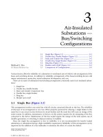
Figure 1.4 shows the loss characteristics for a range of available electrical core-steel materials over a
range of values of magnetic induction (core flux density).
The current that creates rated flux in the core is called the magnetizing current. The magnetizing
circuit of the transformer can be represented by one branch in the equivalent circuit shown in Figure
1.5. The core losses are represented by Rm and the excitation characteristics by Xm. When the magnetizing
current, which is about 0.5% of the load current, flows in the primary winding, there is a small voltage
© 2004 by CRC Press LLC
drop across the resistance of the winding and a small inductive drop across the inductance of the winding.
Wecan represent these impedances as R1 and X1 in the equivalent circuit. However, these voltage drops
are very small and can be neglected in the practical case.
Since the flux flowing in all parts of the core is essentially equal, the voltage induced in any turn placed
around the core will be the same. This results in the unique characteristics of transformers with steel
cores. Multiple secondary windings can be placed on the core to obtain different output voltages. Each
turn in each winding will have the same voltage induced in it, as seen in Figure 1.6. The ratio of the
voltages at the output to the input at no-load will be equal to the ratio of the turns. The voltage drops
in the resistance and reactance at no-load are very small, with only magnetizing current flowing in the
windings, so that the voltage appearing across the primary winding of the equivalent circuit in Figure 1.5
can be considered to be the input voltage. The relationship E1/N1 = E2/N2 is important in transformer
design and application. The term E/N is called “volts per turn.”
A steel core has a nonlinear magnetizing characteristic, as shown in Figure 1.7. As shown, greater
ampere-turns are required as the flux density B is increased from zero. Above the knee of the curve, as
the flux approaches saturation, a small increase in the flux density requires a large increase in the
ampere-turns. When the coresaturates, the circuit behaves much the same as an air core. As the flux
FIGURE 1.4 Loss characteristics for electrical core-steel materials over a range of magnetic induction (core flux
density).
FIGURE 1.5 Equivalent circuit.
© 2004 by CRC Press LLC
density decreases to zero, becomes negative, and increases in a negative direction, the same phenomenon
of saturation occurs. As the flux reduces to zero and increases in a positive direction, it describes a loop
known as the “hysteresis loop.” The area of this loop represents power loss due to the hysteresis effect
in the steel. Improvements in the grade of steel result in a smaller area of the hysteresis loop and a
sharper knee point where the B-H characteristic becomes nonlinear and approaches the saturated state.
1.4The Practical Transformer
1.4.1Magnetic Circuit
Inactual transformer design, the constants for the ideal circuit are determined from tests on materials
and on transformers. For example, the resistance component of the core loss, usually called no-load loss,
is determined from curves derived from tests on samples of electrical steel and measured transformer
no-load losses. The designer will have curves similar to Figure 1.4 for the different electrical steel grades
as a function of induction. Similarly, curves have been made available for the exciting current as a function
of induction.
A very important relationship is derived from Equation 1.11. It can be written in the following form:
B=0.225 (E/N)/(f A)(1.13)
The term E/N is called “volts per turn”: It determines the number of turns in the windings; the flux
density in the core; and is a variable in the leakage reactance, which is discussed below. In fact, when the
FIGURE 1.6 Steel core with windings.
FIGURE 1.7 Hysteresis loop.
E1 = 1000
N1 = 100
E/N = 10
N3 = 20
E3 = 20 v 10 = 200
N2 = 50
E2 = 50 v 10 = 500
© 2004 by CRC Press LLC
designer starts to make a design for an operating transformer, one of the first things selected is the volts
per turn.
The no-load loss in the magnetic circuit is a guaranteed value in most designs. The designer must
select an induction level that will allow him to meet the guarantee. The design curves or tables usually
show the loss per unit weight as a function of the material and the magnetic induction.
The induction must also be selected so that the core will be below saturation under specified
overvoltage conditions. Magnetic saturation occurs at about 2.0 T in magnetic steels but at about 1.4 T
in amorphous ribbon.
1.4.2Leakage Reactance
Additional concepts must be introduced when the practical transformer is considered,. For example, the
flow of load current in the windings results in high magnetic fields around the windings. These fields
are termed leakage flux fields. The term is believed to have started in the early days of transformer theory,
when it was thought that this flux “leaked” out of the core. This flux exists in the spaces between windings
and in the spaces occupied by the windings, as seen in Figure 1.8. These flux lines effectively result in an
impedance between the windings, which is termed “leakage reactance” in the industry. The magnitude
of this reactance is a function of the number of turns in the windings, the current in the windings, the
leakage field, and the geometry of the core and windings. The magnitude of the leakage reactance is
usually in the range of 4 to 20% at the base rating of power transformers.
The load current through this reactance results in a considerable voltage drop. Leakage reactance is
termed “percent leakage reactance” or “percent reactance,” i.e., the ratio of the reactance voltage drop
to the winding voltage
v 100. It is calculated by designers using the number of turns, the magnitudes of
the current and the leakage field, and the geometry of the transformer. It is measured by short-circuiting
one winding of the transformer and increasing the voltage on the other winding until rated current
flows in the windings. This voltage divided by the rated winding voltage
v 100 is the percent reactance
voltage or percent reactance. The voltage drop across this reactance results in the voltage at the load
being less than the value determined by the turns ratio. The percentage decrease in the voltage is termed
“regulation,” which is a function of the power factor of the load. The percent regulation can be deter-
mined using the following equation for inductive loads.
%Reg = %R(cos
J) + %X(sin J) + {[%X(cos J) – %R(sin J)]
2
/200} (1.14)
FIGURE 1.8 Leakage flux fields.
Steel Core
Winding 1
Leakage Flux Lines
Winding 2
© 2004 by CRC Press LLC
where
%Reg = percentage voltage drop across the resistance and the leakage reactance
%R = percentage resistance = (kW of load loss/kVA of transformer)
v100
%X = percentage leakage reactance
J= angle corresponding to the power factor of the load !cos
–1
pf
For capacitance loads, change the sign of the sine terms.
Inorder to compensate for these voltage drops, taps are usually added in the windings. The unique
volts/turn feature of steel-core transformers makes it possible to add or subtract turns to change the
voltage outputs of windings. A simple illustration of this concept is shown in Figure 1.9. The table in
the figure shows that when tap 4 is connected to tap 5, there are 48 turns in the winding (maximum
tap) and, at 10 volts/turn, the voltage E2 is 480 volts. When tap 2 is connected to tap 7, there are 40 turns
in the winding (minimum tap), and the voltage E2 is 400 volts.
1.4.3 Load Losses
The term load losses represents the losses in the transformer that result from the flow of load current in
the windings. Load losses are composed of the following elements.
• Resistance losses as the current flows through the resistance of the conductors and leads
• Eddy losses caused by the leakage field. These are a function of the second power of the leakage
field density and the second power of the conductor dimensions normal to the field.
• Stray losses: The leakage field exists in parts of the core, steel structural members, and tank walls.
Losses and heating result in these steel parts.
Again, the leakage field caused by flow of the load current in the windings is involved, and the eddy
and stray losses can be appreciable in large transformers. In order to reduce load loss, it is not sufficient
to reduce the winding resistance by increasing the cross-section of the conductor, as eddy losses in the
conductor will increase faster than joule heating losses decrease. When the current is too great for a single
conductor to be used for the winding without excessive eddy loss, a number of strands must be used in
parallel. Because the parallel components are joined at the ends of the coil, steps must be taken to
FIGURE 1.9 Illustration of how taps added in the windings can compensate for voltage drops.
E2
8
20 20
765 432
1
2222
E1
E1 = 100
N1 = 10
E/N = 10
E2 = E/N X N2
N2 E2
4 to 5 = 48 E2 = 10 v 48 = 480 Volts
4 to 6 = 46 E2 = 10 v 46 = 460 Volts
3 to 6 = 44 E2 = 10 v 44 = 440 Volts
3 to 7 = 42 E2 = 10 v 42 = 420 Volts
2 to 7 = 40 E2 = 10 v 40 = 400 Volts
© 2004 by CRC Press LLC
circumvent the induction of different EMFs (electromotive force) in the strands due to different loops
of strands linking with the leakage flux, which would involve circulating currents and further loss.
Different forms of conductor transposition have been devised for this purpose.
Ideally, each conductor element should occupy every possible position in the array of strands such
that all elements have the same resistance and the same induced EMF. Conductor transposition, however,
involves some sacrifice of winding space. If the winding depth is small, one transposition halfway through
the winding is sufficient; or in the case of a two-layer winding, the transposition can be located at the
junction of the layers. Windings of greater depth need three or more transpositions. An example of a
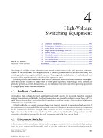
continuously transposed conductor (CTC) cable, shown in Figure 1.10, is widely used in the industry.
CTC cables are manufactured using transposing machines and are usually paper-insulated as part of the
transposing operation.
Stray losses can be a constraint on high-reactance designs. Losses can be controlled by using a
combination of magnetic shunts and/or conducting shields to channel the flow of leakage flux external
to the windings into low-loss paths.
1.4.4 Short-Circuit Forces
Forces exist between current-carrying conductors when they are in an alternating-current field. These
forces are determined using Equation 1.15:
F = B I sin U
where
F = force on conductor
B = local leakage flux density
U = angle between the leakage flux and the load current. In transformers, sin U is almost
always equal to 1
FIGURE 1.10 Continuously transposed conductor cable.
© 2004 by CRC Press LLC
Thus
B = Q I (1.16)
and therefore
F
w I
2
(1.17)
Since the leakage flux field is between windings and has a rather high density, the forces under short-
circuit conditions can be quite high. This is a special area of transformer design. Complex computer
programs are needed to obtain a reasonable representation of the field in different parts of the windings.
Considerable research activity has been directed toward the study of mechanical stresses in the windings
and the withstand criteria for different types of conductors and support systems.
Between any two windings in a transformer, there are three possible sets of forces:
• Radial repulsion forces due to currents flowing in opposition in the two windings
• Axial repulsion forces due to currents in opposition when the electromagnetic centers of the two
windings are not aligned
• Axial compression forces in each winding due to currents flowing in the same direction in adjacent
conductors
The most onerous forces are usually radial between windings. Outer windings rarely fail from hoop
stress, but inner windings can suffer from one or the other of two failure modes:
• Forced buckling, where the conductor between support sticks collapses due to inward bending
into the oil-duct space
• Free buckling, where the conductors bulge outwards as well as inwards at a few specific points on
the circumference of the winding
Forced buckling can be prevented by ensuring that the winding is tightly wound and is adequately
supported by packing it back to the core. Free buckling can be prevented by ensuring that the winding
is of sufficient mechanical strength to be self-supporting, without relying on packing back to the core.
1.4.5 Thermal Considerations
The losses in the windings and the core cause temperature rises in the materials. This is another important
area in which the temperatures must be limited to the long-term capability of the insulating materials.
Refined paper is still used as the primary solid insulation in power transformers. Highly refined mineral
oil is still used as the cooling and insulating medium in power transformers. Gases and vapors have been
introduced in a limited number of special designs. The temperatures must be limited to the thermal
capability of these materials. Again, this subject is quite broad and involved. It includes the calculation
of the temperature rise of the cooling medium, the average and hottest-spot rise of the conductors and
leads, and accurate specification of the heat-exchanger equipment.
1.4.6 Voltage Considerations
A transformer must withstand a number of different normal and abnormal voltage stresses over its
expected life. These voltages include:
• Operating voltages at the rated frequency
• Rated-frequency overvoltages
• Natural lightning impulses that strike the transformer or transmission lines
• Switching surges that result from opening and closing of breakers and switches
• Combinations of the above voltages
© 2004 by CRC Press LLC
• Transient voltages generated due to resonance between the transformer and the network
• Fast transient voltages generated by vacuum-switch operations or by the operation of disconnect
switches in a gas-insulated bus-bar system
This is a very specialized field in which the resulting voltage stresses must be calculated in the windings,
and withstand criteria must be established for the different voltages and combinations of voltages. The
designer must design the insulation system to withstand all of these stresses.
References
Kan, H., Problems related to cores of transformers and reactors, Electra, 94, 15–33, 1984.
© 2004 by CRC Press LLC
2
Equipment Types
2.1 Power Transformers
Introduction • Rating and Classifications • Short-Circuit Duty
• Efficiency, Losses, and Regulation • Construction • Accessory
Equipment • Inrush Current • Transformers Connected
Directly to Generators • Modern and Future Developments
2.2 Distribution Transformers
Historical Background • Construction • General Transformer
Design • Transformer Connections • Operational Concerns •
Transformer Locations • Underground Distribution
Transformers • Pad-Mounted Distribution Transformers •
Transformer Losses • Transformer Performance Model •
Transformer Loading • Transformer Testing •
Transformer Protection • Economic Application
2.3Phase-Shifting Transformers
Introduction • Basic Principle of Application • Load Diagram
of a PST • Total Power Transfer • Types of Phase-Shifting
Transformers • Details of Transformer Design • Details of On-
Load Tap-Changer Application • Other Aspects
2.4Rectifier Transformers
Background and Historical Perspective • New Terminology and
Definitions • Rectifier Circuits • Commutating Impedance •
Secondary Coupling • Generation of Harmonics • Harmonic
Spectrum • Effects of Harmonic Currents on Transformers •
Thermal Tests • Harmonic Cancellation • DC Current Content
• Transformers Energized from a Converter/Inverter •
Electrostatic Ground Shield • Load Conditions • Interphase
Transformers
2.5Dry-Type Transformers
Transformer Taps • Cooling Classes for Dry-Type Transformers
• Winding Insulation System • Application • Enclosures •
Operating Conditions • Limits of Temperature Rise •
Accessories • Surge Protection
2.6Instrument Transformers
Overview • Transformer Basics • Voltage Transformer • Current
Transformer
2.7Step-Voltage Regulators
Introduction • Power Systems Applications • Ratings • Theory
• Auto-Booster • Three-Phase Regulators • Regulator Control •
Unique Applications
2.8Constant-Voltage Transformers
Background • Applications • Procurement Considerations •
Typical Service, Storage, and Shipment Conditions • Nameplate
Data and Nomenclature • New Technology Advancements •
Addendum
H. Jin Sim
Scott H. Digby
Waukesha Electric Systems
Dudley L. Galloway
Galloway Transformer Technology
LLC
Dan Mulkey
Pacific Gas & Electric Company
Gustav Preininger
Consultant
Sheldon P. Kennedy
Niagara Transformer Corporation
Paulette A. Payne
PEPCO
Randy Mullikin
Kuhlman Electric Corp.
Craig A. Colopy
Cooper Power Systems
Arindam Maitra
Anish Gaikwad
Arshad Mansoor
Douglas Dorr
EPRI PEAC Corporation
Ralph Ferraro
Ferraro, Oliver & Associates
Richard F. Dudley
Michael Sharp
Antonio Castanheira
Behdad Biglar
Trench Ltd.
© 2004 by CRC Press LLC
2.9Reactors
Background and Historical Perspective • Applications of
Reactors • Some Important Application Considerations • Shunt
Reactors Switching Transients • Current-Limiting Reactors and
Switching Transients • Reactor Loss Evaluation • De-Q’ing •
Sound Level and Mitigation
2.1 Power Transformers
H. Jin Sim and Scott H. Digby
2.1.1 Introduction
ANSI/IEEE defines a transformer as a static electrical device, involving no continuously moving parts,
used in electric power systems to transfer power between circuits through the use of electromagnetic
induction. The term
power transformer is used to refer to those transformers used between the generator
and the distribution circuits, and these are usually rated at 500 kVA and above. Power systems typically
consist of a large number of generation locations, distribution points, and interconnections within the
system or with nearby systems, such as a neighboring utility. The complexity of the system leads to a
variety of transmission and distribution voltages. Power transformers must be used at each of these points
where there is a transition between voltage levels.
Power transformers are selected based on the application, with the emphasis toward custom design
being more apparent the larger the unit. Power transformers are available for step-up operation, primarily
used at the generator and referred to as generator step-up (GSU) transformers, and for step-down
operation, mainly used to feed distribution circuits. Power transformers are available as single-phase or
three-phase apparatus.
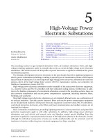
The construction of a transformer depends upon the application. Transformers intended for indoor
use are primarily of the dry type but can also be liquid immersed. For outdoor use, transformers are
usually liquid immersed. This section focuses on the outdoor, liquid-immersed transformers, such as
those shown in Figure 2.1.1.
FIGURE 2.1.1 20 MVA, 161:26.4 v 13.2 kV with LTC, three phase transformers.
© 2004 by CRC Press LLC
2.1.2Rating and Classifications
2.1.2.1Rating
Inthe U.S., transformers are rated based on the power output they are capable of delivering continuously
at a specified rated voltage and frequency under “usual” operating conditions without exceeding pre-
scribed internal temperature limitations. Insulation is known to deteriorate with increases in temperature,
so the insulation chosen for use in transformers is based on how long it can be expected to last by limiting
the operating temperature. The temperature that insulation is allowed to reach under operating condi-
tions essentially determines the output rating of the transformer, called the kVA rating. Standardization
has led to temperatures within a transformer being expressed in terms of the rise above ambient tem-
perature, since the ambient temperature can vary under operating or test conditions. Transformers are
designed to limit the temperature based on the desired load, including the average temperature rise of
a winding, the hottest-spot temperature rise of a winding, and, in the case of liquid-filled units, the top
liquid temperature rise. To obtain absolute temperatures from these values, simply add the ambient
temperature. Standard temperature limits for liquid-immersed power transformers are listed in
Table 2.1.1.
The normal life expectancy of a power transformer is generally assumed to be about 30 years of service
when operated within its rating. However, under certain conditions, it may be overloaded and operated
beyond its rating, with moderately predictable “loss of life.” Situations that might involve operation
beyond rating include emergency rerouting of load or through-faults prior to clearing of the fault
condition.
Outside the U.S., the transformer rating may have a slightly different meaning. Based on some
standards, the kVA rating can refer to the power that can be input to a transformer, the rated output
being equal to the input minus the transformer losses.
Power transformers have been loosely grouped into three market segments based on size ranges. These
three segments are:
1. Small power transformers: 500 to 7500 kVA
2. Medium power transformers: 7500 to 100 MVA
3. Large power transformers: 100 MVA and above
Note that the upper range of small power and the lower range of medium power can vary between 2,500
and 10,000 kVA throughout the industry.
It was noted that the transformer rating is based on “usual” service conditions, as prescribed by
standards. Unusual service conditions may be identified by those specifying a transformer so that the
desired performance will correspond to the actual operating conditions. Unusual service conditions
include, but are not limited to, the following: high (above 40˚C) or low (below –20˚C) ambient temper-
atures, altitudes above 1000 m above sea level, seismic conditions, and loads with total harmonic distor-
tion above 0.05 per unit.
2.1.2.2 Insulation Classes
The insulation class of a transformer is determined based on the test levels that it is capable of with-
standing. Transformer insulation is rated by the BIL, or basic impulse insulation level, in conjunction
with the voltage rating. Internally, a transformer is considered to be a non-self-restoring insulation system,
mostly consisting of porous, cellulose material impregnated by the liquid insulating medium. Externally,
TABLE 2.1.1 Standard limits for Temperature Rises Above Ambient
Average winding temperature rise 65°C
a
Hot spot temperature rise 80°C
Top liquid temperature rise 65°C
a
The base rating is frequently specified and tested as a 55°C rise.
© 2004 by CRC Press LLC
the transformer’s bushings and, more importantly, the surge-protection equipment must coordinate with
the transformer rating to protect the transformer from transient overvoltages and surges. Standard
insulation classes have been established by standards organizations stating the parameters by which tests
are to be performed.
Wye-connected windings in a three-phase power transformer will typically have the common point
brought out of the tank through a neutral bushing. (See Section 2.2, Distribution Transformers, for a
discussion of wye connections.) Depending on the application — for example in the case of a solidly
grounded neutral versus a neutral grounded through a resistor or reactor or even an ungrounded neutral
— the neutral may have a lower insulation class than the line terminals. There are standard guidelines
for rating the neutral based on the situation. It is important to note that the insulation class of the neutral
may limit the test levels of the line terminals for certain tests, such as the applied-voltage or “hi-pot” test,
where the entire circuit is brought up to the same voltage level. A reduced voltage rating for the neutral
can significantly reduce the cost of larger units and autotransformers compared with a fully rated neutral.
2.1.2.3 Cooling Classes
Since no transformer is truly an “ideal” transformer, each will incur a certain amount of energy loss,
mainly that which is converted to heat. Methods of removing this heat can depend on the application,
the size of the unit, and the amount of heat that needs to be dissipated.
The insulating medium inside a transformer, usually oil, serves multiple purposes, first to act as an
insulator, and second to provide a good medium through which to remove the heat.
The windings and core are the primary sources of heat, although internal metallic structures can act
as a heat source as well. It is imperative to have proper cooling ducts and passages in the proximity of
the heat sources through which the cooling medium can flow so that the heat can be effectively removed
from the transformer. The natural circulation of oil through a transformer through convection has been
referred to as a “thermosiphon” effect. The heat is carried by the insulating medium until it is transferred
through the transformer tank wall to the external environment. Radiators, typically detachable, provide
an increase in the surface area available for heat transfer by convection without increasing the size of the
tank. In smaller transformers, integral tubular sides or fins are used to provide this increase in surface
area. Fans can be installed to increase the volume of air moving across the cooling surfaces, thus increasing
the rate of heat dissipation. Larger transformers that cannot be effectively cooled using radiators and
fans rely on pumps that circulate oil through the transformer and through external heat exchangers, or
coolers, which can use air or water as a secondary cooling medium.
Allowing liquid to flow through the transformer windings by natural convection is identified as
“nondirected flow.” In cases where pumps are used, and even some instances where only fans and radiators
are being used, the liquid is often guided into and through some or all of the windings. This is called
“directed flow” in that there is some degree of control of the flow of the liquid through the windings.
The difference between directed and nondirected flow through the winding in regard to winding arrange-
ment will be further discussed with the description of winding types (see Section 2.1.5.2).
The use of auxiliary equipment such as fans and pumps with coolers, called forced circulation, increases
the cooling and thereby the rating of the transformer without increasing the unit’s physical size. Ratings
are determined based on the temperature of the unit as it coordinates with the cooling equipment that
is operating. Usually, a transformer will have multiple ratings corresponding to multiple stages of cooling,
as the supplemental cooling equipment can be set to run only at increased loads.
Methods of cooling for liquid-immersed transformers have been arranged into cooling classes iden-
tified by a four-letter designation as follows:
© 2004 by CRC Press LLC