electrical power cable engineering (2)
Bạn đang xem bản rút gọn của tài liệu. Xem và tải ngay bản đầy đủ của tài liệu tại đây (747.21 KB, 11 trang )
CHAPTER
2
BASIC
DIELECTRIC
THEORY
OF
CABLE
Theodore
A.
Balaska
and
Carl
C.
Landinger
12-1,
24
1.
INTRODUCTION
Whether being used to
convey
electric power
or
signals,
it is the purpose
of
a
wire
or
cable to
convey
the electric
current
to the intended device
or
location.
In
order
to accomplish
this,
a
conductor
is
provided
which
is adequate to
convey
the electric current imposed.
Equally
important
is
the
need
to
keep
the current
from
flowing in unintended paths rather
than
the
conductor provided.
Insulation
is
provided
to
largely isolate the conductor
from
other paths
or
surfaces
through
which the
current
might
flow.
Therefore,
it
may
be
said
that
any
conductor conveying electric signals
or
power is
an
insulated conductor.
2.
AIR
INSULATED CONDUCTORS
A
metallic conductor suspended
from
insulating supports, surrounded
by
air,
and
carrying
electric
signals
or power may be considered
as
the simplest case
of
an insulated conductor. It also presents an
apportunitY
to easily visualize the
parameters involved.
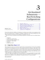
Fikm
2-1
Location
of
Voltage
and
Current
In
Figure
2-1,
clearly the voltage is
between
the
conductor and the ground
[2-3,
2-41.
Also,
because
of the charge
separation,
there is
a
capacitor and
a
large
resistance
between conductor and
ground.
Finally,
as
long
as
ground
is
well
15
Copyright © 1999 by Marcel Dekker, Inc.
away from the conductor, the electric field lines leave the conductor as
reasonably straight lines emanating from the center
of
the conductor. We know
that all bend to ultimately terminate at ground.
Air
is
not a very
good
insulating material since it has a lower voltage
breakdown strength than many other insulating materials. It
is
low in cost
if
space
is
not a constraint.
As
the voltage
between
the conductor and ground
is
increased, a point
is
reached where the electric stress at the conductor exceeds
the breakdown strength or air.
At
this point, the
air
literally breaks down
producing a layer of ionized, conducting air surrounding the conductor. The
term for this is
col~lna
(crown). It represents
power
loss and
can
cause
interference
to
radio,
TV,
and other
signals.
It
is
not uncommon
for
this
condition to appear at isolated spots where
a
rough burr appears on the
conductor or at
a
connector.
This
is
simply
because
the electric
stress
is
locally
increased by the sharpness of the irregularity
or
protrusion
from
the conductor.
In
air
or
other
gasses,
the effect
of
the
ionized
gas
layer surrounding
the
conductor
is
to increase the electrical diameter
of
the conductor to a point
where the air beyond the ionized boundary
is
no longer stressed to breakdown
for
the prevailing temperature, pressure, and humidity. The unlimited supply of
fresh air and the conditions just mentioned, precludes the progression
of
the
ionization
of
air
all
the way to ground.
It
is
possible that the stress level is
so
high that an ionized channel can breach the entire gap from conductor to
earth,
but
this
generally
requires
a very high voltage
source
such as lightning.
3.
INSULATING
TO
SAVE
SPACE
Space
is
a common constraint that precludes the use
of
air as an insulator.
Imagine the space requirements
to
wire a house or apartment using bare
conductors on supports with air as the insulation.
Let’s
consider the next
step
where some
of
the air surrounding the previous conductor
is
replaced with a
better insulating material
also
known
as a dielectric.
In Figure
2-2,
we
see
that the voltage from conductor to
ground
is
the same
as
before.
A
voltage divider has been created that
is
made up the impedance from
the covering surface to ground. The distribution
of
voltage from conductor to
the surface
of
the covering and from the covering surface to ground will
be
in
proportion to these impedances. It
is
important to note that with ground
relatively far away from the covered conductor, the majority of the voltage
exists from the covering surface to ground. Putting this another way, the outer
surface
of
the covering has a voltage
that
is within a few percent
of
the voltage
on the conductor
(95
to
97%
is a common value).
16
Copyright © 1999 by Marcel Dekker, Inc.
Voltage to
Ground
So
little current is available at the covering dace from a
low
voltage covering
(600
volts
or
less),
that it is imperceptible. When
this
condition
exists
with
some level of confidence, the ‘‘cowing’’
is
then considered to
be
“insulation”
and suitable
for
continuous contact
by
a
grounded
dace
as
long
as
such
contact does
not
result
in
chemical
or
thermal degradation. The question
arises
as
to what is considered to
be
low
voltage. The voltage rating
of
insulated
cables
is
based
on
the
phase-to-phase
voltage.
Low
voltage
is
generally
considered
to
be
less
than
600
volts phase-to-phase.
See
Chapters
4
and
9
for
additional information.
+.
Voltage from dace
of
covering to ground
Because
of the proximity and contact
with
other
objects,
the thickness of
indating materials
used
for
low
voltage
cables
is
generally
based
on
mechanical
requirements rather
than
electrical.
The
surrounding
environment,
the
need
for
special
properties
such
as
sunlight,
or
flame
resistance, and
rigors
of
installation
often
make
it dBicult
for
a single material
satisfy
all related
requirements. Designs involving
two
or
more layers
are
commonly
used
in
low
voltage cable
designs.
4.
AS
THE
VOLTAGE RISES
Return
to
the metallic conductor that
is
mered with
an
insulating material and
suspended in
air.
When the ground plane
is
brought
close
or
touches the
covering, the electric field lines become increasingly
distorted.
17
Copyright © 1999 by Marcel Dekker, Inc.
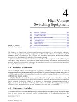
Figure
2-3
Electric Field Lines Bend to Terminate at Ground Plane
7
Conductor
In Figure
2-3,
we
see
considerable bending
of
the electric field lines.
Recognizing that equipdential lines are perpendicular to the field lines, the
bending results in potential difference on the covering surface.
At
low voltages,
the effect
is
negligible.
As
the voltage increases, the point
is
reached where the
potential gradients are su&cient to cause current to flow across the surface
of
the covering. This is commonly known as “tracking.” Even though the
currents
are small, the high surface resistance causes heating to take place which
ultimately damages the covering.
If
this condition is allowed to continue,
eventually the erosion
may
progress to failure.
It
is
important
to
note that the utilization
of
spacer cable systems
and
heavy
walled tree wires depend
on
this ability
of
the covering
to
reduce current flow to
a minimum. When sustained contact with branches, limbs,
or
other objects
occurs, damage
may
result
hence such contacts may not
be
left
permanently.
At
first,
it might
be
thought that the solution
is
to continue to add insulating
covering thickness as the operating voltage increases. Cost and complications
involved in overcoming this di€ficulty would make
this
a desirable
first
choice.
Unfortunately, surface erosion and personnel hazards are not linear
functions
of
voltage versus thickness and this approach becomes impractical.
4.1
The
Insulation
Shield
In
order
to
make permanent ground contact possible,
a
semiconducting
or
resistive layer may be place Over the insulation
surface.
This material
forces
the
18
Copyright © 1999 by Marcel Dekker, Inc.
ending
of
the field lines to
occur
in the
semiconducting
layer.
This
layer creates
some complications, however.
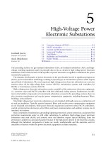
Figure
2-4
Conductor
,
Conductor to
SC
Layer
Semiconducting
(SC)
Layer
'
Voltage,
SC
Surface
to Ground
I
.f,
Ground
In Figure
2-4,
it is
clear
that a capacitor
has
been
created
from
the
conductor to
the
surEace
of semiconducting layer.
A
great deal of charge
can
be
contained
in
this
capacitor.
This
charging current must
be
controlled
so
that a path
to
ground
is
not established
along
the
surface
of the semiconducting layer.
This
path
can
lead
to
burning and ultimate
failure
of
that
layer.
Accidental human
contact would
be
a
very serious alternative. It is clearly necessary to provide a
continuous contact with ground that provides
an
adequate
path to drain the
capacitive charging
current
to ground without damage to the cable.
This
is done
by
adding a metallic path
in
contact with the semiconducting shield.
Once
a
metallic member
has
been
added to the shield system, there is
simply
no
way
to avoid its presence under ground fault umditions.
This
must
be
considered
by
either providing adequate conductive
capacity
in the shield
to
handle
the
fault currents
or
to provide supplemental means to accomplish
this.
This
is a critical factor
in
cable design.
Electric
utility
cables have fault current requirements that are sufficiently large
that it
is
common
to
provide
for
a
neutral in
the
design of the metallic shield.
These
cables
have become
known
as
Underground Residential Distribution
(VRD)
and Underground Distribution
(UD)
style cables. It
is
important
that
the
functions
of the metallic shield system
are
understood
since
many
serious
errors
and accidents
have cmumd
because
the functions were misunderstood. The
maximum
stress
occus
at the conductor.
19
Copyright © 1999 by Marcel Dekker, Inc.
4.2
A Conductor Shield is Needed
The presence
of
an
insulation shield creates another complication. The
grounded insulation shield results in the entire voltage stress being placed
across the insulation.
Just as in the case
of
the air insulated conductor, there
is
concern about
exceeding maximum
stress
that the insulating layer can withstand. The
problem is magnified
by
stranded conductors
or
burrs and scratches that may be
present in both stranded and solid conductors.
Figure
2-5
A
Conductor Shield
is
Added to Provide
a
Smooth
Inner Electrode
Conductor Shield
.
%.
In
Figure
2-5,
a semiconducting layer has
been
added
over the conductor to
smooth out
any
irregularities.
This
reduces the probability
of
protrusions into
the insulating layer.
Protrusions
into the
insulation
or
into the semiconducting
layer increase the localized stress (stress enhancement) that may exceed the
long term breakdown strength
of
the insulation. This
is
especially critical in the
case of extruded dielectric insulations. Unlike air, there
can
be
no
fresh supply
of
insulation. Any damage will be progressive and lead to total breakdown
of
the insulating layer. There will be more discussion about
“treeing” in
Chapter
16.
4.3
Shielding Layer Requirements
There are certain requirements inherent in shielding layers to reduce
stress
enhancement. First, protrusions, whether
by
material smoothness
or
manufacturing, must
be
minimized. Such protrusions defeat the very purpose
of
a shield
by
enhancing electrical
stress.
The
insulations
shield layer
has
a
further complication
in
that
it
is
desirable to
have
it
easily removable
to
facilitate splicing and terminating, This certainly is
the
case
in the medium
voltage
(5
to
35
kv).
At higher voltages, the inconveniences
of
a bonded
20
Copyright © 1999 by Marcel Dekker, Inc.
insulation shield can
be
tolerated
to
gain the additional probability of
a
smooth,
void-& insulation-insulation shield interface for cable with
a
bonded shield.
4.4
Insulation
Layer Requirements
At
medium and higher voltages, it is critical that
both
the insulation and
insulation-sbield interfaces
be
contamination
free.
Contamination results in
stress
enhancement that can
increase
the probability of breakdown. Voids can
do
the same with the additional possibility
of
capacitive-resistive
(CR)
discharges
in
the
gas-filled
void as voltage gradients appear across the void.
Such discharges can
be
destructive
of the surrounding insulating material and
lead to progressive deterioration and breakdown.
4.5
Jackets
In
low voltage applications, jackets are commonly
used
to protect underlying
layers
from physical abuse, sunlight, flame
or
chemical attack. Chemical attack
includes corrosion of underlying metallic layers for shielding and armoring. In
multi-conductor designs,
overall
jackets are common for the same
purposes.
For
medium and high voltage cables, jackets have
been
almost universally
used
throughout the history of cable designs. They are used
for
the same purposes
as
for
low
voltage cables with special emphasis
on
protecting underlying metallic
components
from
corrosion. The only exceptions
were
paper-insulated, lead-
covered
cables and
early
URD/UD
designs that were widely
used
by
the electric
utility industry. Both “experiments” were
based
on the assumption that
lead,
and subsequently copper
wires,
were not subject to significant corrosion.
Both
experiments resulted in elevated failure rates
for
these designs. Jackets
are
presently
used
for
these
designs.
5.
TERMINOLOGY
12-11
To
better understand the terminology that
will
be
used
throughout
this
book,
a
brief
invoduction
of
the
terms follows.
5.1
Medium Voltage
Sbielded
Cables
Medium
voltage
(5
kV to
46
kV)
shielded cable appears
to
be
a
relatively
simple
electrical
machine.
It
does
electrical
work
but
there
are
no
parts
that
move, at
least
no
discernible
movement to the naked eye.
Do
not
be
misled.
This
cable
is
a
sophisticated electrical machine, even though it looks
commonplace. To know why it is
constructed
the
way
it
is,
let
us
first
look at a
21
Copyright © 1999 by Marcel Dekker, Inc.
relatively simple cable, a low voltage non-shielded cable. For simplicity, we
shall contine
this
discussion to single conductor cable.
5.1.1
components in
this
cable, a conductor and its overlying insulation.
Basic Components
of
Non-Shielded Power Cable. There
are
only two
5.1.2 Conductor.
The
conductor may
be
solid
or
stranded and
its
metal usually
is either copper
or
aluminum.
An
attempt to
use
sodium
was short-lived. The
strand can
be
concentric, compressed, compacted, segmental,
or
annular to
achieve desired properties
of
flexibility, diameter, and current density.
Assuming the same cross-sectional
area
of
conductor, there is a difference in
diameters between solid and the
various
stranded conductors.
This
diameter
differential
is
an
important consideration in selecting
methods
to
effect joints,
terminations, and fill
of
conduits.
5.1.3
Electrical Insulation (Dielectric).
This
provides dicient separation
between the conductor and the nearest electrical ground to preclude dielectric
failure.
For
low voltage cables, (2,000 volts and below), the
required
thickness
of
insulation to physically protect the conductor is
more
than
adequate for
required
dielectric strength.
5.1.4
Dielectric Field. The conductor and the insulation are visible to the
unaided
eye. However, there is a
third
component in
this
cable.
It
is invisible to
the unaided
eye.
This
third
component
is
what contributes to sophistication
of
the electrical machine known
as
cable. Alternating curtent fields will
be
discussed, not
direct
current
In
all
cables, regardless
of
their
kV
ratings, there exists a dielectric field
whenever
the
conductor
is
energized.
This
dielectric field
can
be visualized
by
lines
of
electrostatic
flux
and equi-potentials. Electrostatic
flux
lines represent
the boundaries
of
dielectric
flux
between electrodes having different electrical
potentials. Eaui-mtential lines represent points
of
equal
potential difference
between electrodes having Werent electrical potentials.
They
represent the
radial voltage
stresses
in the insulation and their relative spacing indicates the
magnitude
of
the voltage
stress.
The closer the lines, the higher the stress.
See
Figures 2-1, 2-2, and 2-3.
If
the cable is at
an
infinite
distance from electrical
ground
(ideal
situation),
there will
be
no distortion
of
this
dielectric field. The electrostatic flux lines
will
radiate between the conductor and the surface
of
the cable insulation
With
symmetrical
spacing between them. The lines
of
equi-potential
will
be
22
Copyright © 1999 by Marcel Dekker, Inc.
concentric with relation to
the
conductor and the
surface
of
the cable insulation.
However, in actual practice
this
ideal situation does not exist.
In actual practice, the
fluface
of the cable insulation is
expected
to be
in
contact
with
an
electrical ground.
This
actual operating condition creates
distortion
in
the dielectric field. The lines of electtostatic
flux
are crowded in the
area
of the
insulation closest
to
ground.
The lines
of
equi-potential
are
eccentric
with
respect
to the conductor and the
surface
of
the cable insulation.
This
situation is tolerated
if
the dielectric
strength
of the cable insulation is suflicient to
resist
the flow
of
electrons (lines
of electrostatic
flux),
and
the
surface
discharges and internal voltage stresses
that are due to cuncentrated voltage gradients
(stresses)
that are
rep-
by
lhes
of equi-potential.
Low
voltage, non-shielded cables
are
designed to
withstand this condition.
Service performance of non-shielded cables
is
generally considered acceptable. Thus one
may
ask
“Why
not extrapolate
non-
shielded
cable
wall thickness for increasing voltages?”
There
are
very practical
limits,
economics
being paramount, to such an approach.
5.1.5
Extrapolation of
600
Volt
and
5
kV Cable
Walls.
If
we
use
the same
volts per
mil
wall thickness
of
600
volt cable to determine higher voltage walls,
we
achieve a wall
of
at least
4.6
inches
(1
17
mm)
for a
35
kV cable.
A
similar approach using
5
kV
cable voltage stress
as
the
basis
for
extrapolation provides at least a
0.63
inch
(16
mm)
wall for a
35
kV cable.
5.1.6
Summary
of Limitation. It
is
apparent that the bulk
dimensions
created
by
extrapolation of non-shielded cable walls
are
unacceptable.
To
overcome
this
situation
of
bulk
dimensions,
generally shielded cable
is
used.
5.2
Basic
Componenb
of
a
Sbielded
Power
Cable
The essential additional component is shielding.
However,
where
is it
placed,
what materials
are
used,
and what does it do to the dielectric field?
Let
us
start
from
the conductor
again
and
move outward from the center of the cable.
5.2.1
Conductor. Nothing unusual
as
compared
to
a
non-shielded cable.
5.2.2
Conductor Shield.
A
conducting material
is
placed over the conductor
circumfmnce to
screen
(shield)
out
irregularities of the conductor contours.
The dielectric field will not
be
affacted
or
“see”
the
shape
of
the outer strands
23
Copyright © 1999 by Marcel Dekker, Inc.
(or
other conductor contours) due to the presence of the conductor shield
(screen).
5.2.3
Electrical Insulation (Dielectric). The differences between insulation for
a non-shielded cable as
compared
to a shielded cable are in material, quality,
cleanliness, and application. The thickness applied is primarily influenced by
considerations
of
electrical stress (voltage gradients).
5.2.4
Insulation Shield. This is a two-part system, consisting
of
an auxiliary
shield and a primary shield.
5.2.5
Auxiliary Shield.
A
conducting material that is placed over the outer
diameter of the cable insulation. This material
must
be
capable of conducting
“leakage” current radially through its wall without creating an abnormal
voltage
drop.
5.2.6
primary Shield.
A
metallic layer of tapes, wires,
or
a tube that is placed
over the circumference of the underlying auxiliary shield. This must
be
capable
of
conducting the summation
of
“leakage” currents and
cany
them to the
nearest ground without creation
of
an abnormal voltage drop.
5.2.7
Dielectric Field. A dielectric field, composed
of
electrostatic
flux
and
equi-potential lines, exists when the conductor
is
energized. There is
no
distortion in this dielectric field because of the shielding of insulation and
conductor, Electrostatic
flux
lines are symmetrically spaced and equi-potential
lines are concentric.
See
Figure
2-3.
However,
observe features not previously noted; the electrostatic
flux
and equi-
potential lines are
spaced
closer together near the conductor shield as compared
to
their spacing near the insulation shield. This
is
why we are cognizant
of
maximum
stresses
at
areas
of minimum radii (and diameters). Insulation voids
at the conductor shield are more critical than voids at the insulation shield.
Also
these
lines are
spaced
closer together at the minimum diameter
(or
radii).
This substantiates the maximum radial
stress
theory.
5.2.8
Insulation Thickness. The use of shielded cable permits using cables that
are more economic to manufacture and install as compared to non-shielded
cables that would require very heavy insulation thickness. Table
2-2
provides a
oomparison.
5.2.9
Jacket or Outer Coverings. Over the insulation shielding system, the
cable contains components that provide environmental protection for the cable.
24
Copyright © 1999 by Marcel Dekker, Inc.
This
can
be
extruded jacket
(of
synthetic material), metal
sheath
or
wires,
armoring,
of
a combination
of
these items.
6.
REFERENCES
[2-11
Balaska,
T.
A.,
adapted
from
class
notes for “Power Cable Engineering
Clinic,”
University
of Wisconsin
Madison,
1992.
[2-21
Landinger, Carl, adapted from
class
notes for “Power Cable Engineering
Clinic,” University
of
Wisconsin
-
Madison,
1997.
[2-31
A.
Clapp,
C. C.
hdinger,
and W. A. Thue,
“Design
and
Application
of
Aerial
Systems
Using
Insulating
and
covered
Wire
and
Cable,”
Proceedings
of
the
1996
IEEEPES
TransmissJon and Distribution Conference,
%CH35%8,
Los
Angeles, CA,
!kpt.
15-20, 1996.
[2-4]
A. Clapp,
C.
C. Landinger, and
W.
A.
Thue,
“Safety
Considerations
of
Aerial
Systems
Using
Insulating
and
Covered Wire and Cable,”
Proceedings
of
the
1996
IEEEQES
Transmission and Distribution Conference,
%CH35%8,
Los
Angeles, CA, Sept.
15-20, 1996.
25
Copyright © 1999 by Marcel Dekker, Inc.