power system stability and control chuong (6)
Bạn đang xem bản rút gọn của tài liệu. Xem và tải ngay bản đầy đủ của tài liệu tại đây (143.19 KB, 14 trang )
II
Electric Power
Generation:
Conventional
Methods
Rama Ramakumar
Oklahoma State University
4 Hydroelectric Power Generation Steven R. Brockschink, James H. Gurney,
and Douglas B. Seely 4-1
Planning of Hydroelectric Facilities
.
Hydroelectric Plant Features
.
Special Considerations Affecting Pumped Storage Plants
.
Commissioning
of Hydroelectric Plants
5 Synchronous Machinery Paul I. Nippes 5-1
General
.
Construction
.
Performance
6 Thermal Generating Plants Kenneth H. Sebra 6-1
Plant Auxiliary System
.
Plant One-Line Diagram
.
Plant Equipment
Voltage Ratings
.
Grounded vs. Ungrounded Systems
.
Miscellaneous
Circuits
.
DC Systems
.
Power Plant Switchgear
.
Auxiliary Transformers
.
Motors
.
Main Generator
.
Cable
.
Electrical Analysis
.
Maintenance
and Testing
.
Start-Up
7 Distributed Utilities John R. Kennedy 7-1
Available Technologies
.
Fuel Cells
.
Microturbines
.
Combustion Turbines
.
Storage Technologies
.
Interface Issues
.
Applications
.
Conclusions
ß 2006 by Taylor & Francis Group, LLC.
ß 2006 by Taylor & Francis Group, LLC.
4
Hydroelectric Power
Generation
Steven R. Brockschink
Stantec Consulting
James H. Gurney
BC Transmission Corporation
Douglas B. Seely
Stantec Consulting
4.1 Planning of Hydroelectric Facilities 4-1
Siting
.
Hydroelectric Plant Schemes
.
Selection of Plant
Capacity, Energy, and Other Design Features
4.2 Hydroelectric Plant Features 4-2
Turbine
.
Flow Control Equipment
.
Generator
.
Generator
Terminal Equipment
.
Generator Switchgear
.
Generator
Step-Up Transformer
.
Excitation System
.
Governor System
.
Control Systems
.
Protection Systems
.
Plant Auxiliary
Equipment
4.3 Special Considerations Affecting Pumped
Storage Plants 4-10
Pump Motor Starting
.
Phase Reversing of the
Generator=Motor
.
Draft Tube Water Depression
4.4 Commissioning of Hydroelectric Plants 4-11
Hydroelectric power generation involves the storage of a hydraulic fluid, water, conversion of the
hydraulic (potential) energy of the fluid into mechanical (kinetic) energy in a hydraulic turbine, and
conversion of the mechanical energy to electrical energy in an electric generator.
The first hydroelectric power plants came into service in the 1880s and now comprise approximately
20% (700 GW) of the world’s installed generation capacity (World Energy Council, 2001). Hydroelec-
tricity is an important source of renewable energy and provides significant flexibility in base loading,
peaking, and energy storage applications. While initial capital costs are high, the inherent simplicity of
hydroelectric plants, coupled with their low operating and maintenance costs, long service life, and high
reliability, make them a very cost-effective and flexible source of electricity generation. Especially
valuable is their operating characteristic of fast response for start-up, loading, unloading, and following
of system load variations. Other useful features include their ability to start without the availability of
power system voltage (black start capability), ability to transfer rapidly from generation mode to
synchronous-condenser mode, and pumped storage application.
Hydroelectric units have been installed in capacities ranging from a few kilowatts to nearly 1 GW.
Multi-unit plant sizes range from a few kilowatts to a maximum of 18 GW.
4.1 Planning of Hydroelectric Facilities
4.1.1 Siting
Hydroelectric plants are located in geographic areas where they will make economic use of hydraulic
energy sources. Hydraulic energy is available wherever there is a flow of liquid and accumulated head.
Head represents potential energy and is the vertical distance through which the fluid falls in the energy
conversion process. The majority of sites utilize the head developed by freshwater; however, other
ß 2006 by Taylor & Francis Group, LLC.
liquids such as saltwater and treated sewage have been utilized. The siting of a prospective hydroelectric
plant requires careful evaluation of technical, economic, environmental, and social factors. A significant
portion of the project cost may be required for mitigation of environmental effects on fish and wildlife
and relocation of infrastructure and population from flooded areas.
4.1.2 Hydroelectric Plant Schemes
There are three main types of hydroelectric plant arrangements, classified according to the method of
controlling the hydraulic flow at the site:
1. Run-of-the-river plants, having small amounts of water storage and thus little control of the flow
through the plant.
2. Storage plants, having the ability to store water and thus control the flow through the plant on a
daily or seasonal basis.
3. Pumped storage plants, in which the direction of rotation of the turbines is reversed during off-
peak hours, pumping water from a lower reservoir to an upper reservoir, thus ‘‘storing energy’’
for later production of electricity during peak hours.
4.1.3 Selection of Plant Capacity, Energy, and Other Design Features
The generating capacity of a hydroelectric plant is a function of the head and flow rate of water
discharged through the hydraulic turbines, as shown in the following equation:
P ¼ 9:8 h QH (4:1)
where P ¼ power (kilowatts)
h ¼ plant efficiency
Q ¼ discharge flow rate (m
3
=s)
H ¼ head (m)
Flow rate and head are influenced by reservoir inflow, storage characteristics, plant and equipment
design features, and flow restrictions imposed by irrigation, minimum downstream releases, or flood
control requirements. Historical daily, seasonal, maximum (flood), and minimum (drought) flow
conditions are carefully studied in the planning stages of a new development. Plant capacity, energy,
and physical features such as the dam and spillway structures are optimized through complex economic
studies that consider the hydrological data, planned reservoir operation, performance characteristics of
plant equipment, construction costs, the value of capacity and energy, and financial discount rates. The
costs of substation, transmission, telecommunications, and off-site control facilities are also important
considerations in the economic analysis. If the plant has storage capability, then societal benefits from
flood control may be included in the economic analysis.
Another important planning consideration is the selection of the number and size of generating units
installed to achieve the desired plant capacity and energy, taking into account installed unit costs, unit
availability, and efficiencies at various unit power outputs (American Society of Mechanical Engineers–
Hydropower Technical Committee, 1996).
4.2 Hydroelectric Plant Features
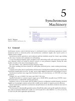
Figures 4.1 and 4.2 illustrate the main components of a hydroelectric generating unit. The generating
unit may have its shaft oriented in a vertical, horizontal, or inclined direction depending on the physical
conditions of the site and the ty pe of turbine applied. Figure 4.1 shows a typical vertical shaft Francis
turbine unit and Fig. 4.2 shows a horizontal shaft propeller turbine unit. The following sections will
describe the main components such as the turbine, generator, switchgear, and generator transformer, as
well as the governor, excitation system, and control systems.
ß 2006 by Taylor & Francis Group, LLC.
Switchboard
Headwater
Level
Governor
To Switchyard
To Switchyard
Main
Transformer
Circuit
Breaker
Generator
Main Leads
Speed Signal
Generator
Excitation
Transformer
Upper Guide
Bearing
Intake
Gate
Penstock
Generator
Lower Guide Bearing
Thrust Bearing
Shaft Coupling
Packing Box
Wicket Gates
Spiral Case
Turbine Runner
Tailrace
Draft Tube
Tailwater
Level
Turbine Guide Bearing
Head Cover
Rotor
Excitation
and Voltage
Regulation
Control
Circuit
Breaker
Stator
FIGURE 4.1 Vertical Francis unit arrangement. (From IEEE Standard 1020, IEEE Guide for Control of Small
Hydroelectric Power Plants. Copyright IEEE. All rights reserved.)
To
Switchyard
Main
Transformer
Circuit
Breaker
Excitation
Transformer
Circuit
Breaker
Switchboard
Intake
Gate
Headwater
Level
Governor
Thrust
Bearing
Speed
Increaser
Rotor
Stator
Tailwater
Level
Turbine
Runner
Wicket Gates
Speed
Signal
Generator
Excitation
and Voltage
Regulation
Control
FIGURE 4.2 Horizontal axial-flow unit arrangement. (From IEEE Standard 1020, IEEE Guide for Control of Small
Hydroelectric Power Plants. Copyright IEEE. All rights reserved.)
ß 2006 by Taylor & Francis Group, LLC.
4.2.1 Turbine
The type of turbine selected for a particular application is influenced by the head and flow rate. There
are two classifications of hydraulic turbines: impulse and reaction.
The impulse turbine is used for high heads—approximately 300 m or greater. High-velocity jets of
water strike spoon-shaped buckets on the runner which is at atmospheric pressure. Impulse turbines
may be mounted horizontally or vertically and include perpendicular jets (known as a Pelton type),
diagonal jets (known as a Turgo type), or cross-flow types.
In a reaction turbine, the water passes from a spiral casing through stationary radial guide vanes,
through control gates and onto the runner blades at pressures above atmospheric. There are two
categories of reaction turbine—Francis and propeller. In the Francis turbine, installed at heads up to
approximately 360 m, the water impacts the runner blades tangentially and exits axially. The propeller
turbine uses a propeller-type runner and is used at low heads—below approximately 45 m. The
propeller runner may use fixed blades or variable pitch blades—known as a Kaplan or double regulated
type—that allows control of the blade angle to maximize turbine efficiency at various hydraulic heads
and generation levels. Francis and propeller turbines may also be arranged in a slant, tubular, bulb, and
rim generator configurations.
Water discharged from the turbine is directed into a draft tube where it exits to a tailrace channel,
lower reservoir, or directly to the river.
4.2.2 Flow Control Equipment
The flow through the turbine is controlled by wicket gates on reaction turbines and by needle nozzles on
impulse turbines. A turbine inlet valve or penstock intake gate is provided for isolation of the turbine
during shutdown and maintenance.
Spillways and additional control valves and outlet tunnels are provided in the dam structure to pass
flows that normally cannot be routed through the turbines.
4.2.3 Generator
Synchronous generators and induction generators are used to convert the mechanical energy output of
the turbine to electrical energy. Induction generators are used in small hydroelectric applications (less
than 5 MVA) due to their lower cost which results from elimination of the exciter, voltage regulator, and
synchronizer associated with synchronous generators. The induction generator draws its excitation
current from the electrical system and thus cannot be used in an isolated power system.
The majority of hydroelectric installations utilize salient pole synchronous generators. Salient pole
machines are used because the hydraulic turbine operates at low speeds, requiring a relatively large
number of field poles to produce the rated frequency. A rotor with salient poles is mechanically better
suited for low-speed operation, compared to round rotor machines, which are applied in horizontal axis
high-speed turbo-generators.
Generally, hydroelectric generators are rated on a continuous-duty basis to deliver net kVA output at a
rated speed, frequency, voltage, and power factor and under specified ser vice conditions including the
temperature of the cooling medium (air or direct water). Industry standards specify the allowable
temperature rise of generator components (above the coolant temperature) that are dependent on the
voltage rating and class of insulation of the windings (ANSI, C50.12; IEC, 60034-1). The generator
capability curve (Fig. 4.3) describes the maximum real and reactive power output limits at rated voltage
within which the generator rating will not be exceeded with respect to stator and rotor heating and other
limits. Standards also provide guidance on short-circuit capabilities and continuous and short-time
current unbalance requirements (ANSI, C50.12; IEEE, 492).
Synchronous generators require direct current field excitation to the rotor, provided by the excitation
system described in the section entitled ‘‘Excitation System’’. The generator saturation curve (Fig. 4.4)
describes the relationship of terminal voltage, stator current, and field current.
ß 2006 by Taylor & Francis Group, LLC.
While the generator may be vertical or horizontal, the majority of new installations are vertical. The
basic components of a vertical generator are the stator (frame, magnetic core, and windings), rotor
(shaft, thrust block, spider, rim, and field poles with windings), thrust bearing, one or two guide
bearings, upper and lower brackets for the support of bearings and other components, and sole plates
which are bolted to the foundation. Other components may include a direct connected exciter, speed
signal generator, rotor brakes, rotor jacks, and ventilation systems with surface air coolers (IEEE, 1095).
The stator core is composed of stacked steel laminations attached to the stator frame. The stator
winding may consist of single turn or multiturn coils or half-turn bars, connected in series to form
a three phase circuit. Double layer windings, consisting of two coils per slot, are most common. One
or more circuits are connected in parallel to form a complete phase winding. The stator winding is
normally connected in wye configuration, with the neutral grounded through one of a number of
alternative methods that depend on the amount of phase-to-ground fault current that is permitted
to flow (IEEE, C62.92.2, C37.101). Generator output voltages range from approximately 480 VAC to
22 kVAC line-to-line, depending on the MVA rating of the unit. Temperature detectors are installed
between coils in a number of stator slots.
The rotor is normally comprised of a spider frame attached to the shaft, a rim constructed of solid
steel or laminated rings, and field poles attached to the rim. The rotor construction will vary significantly
depending on the shaft and bearing system, unit speed, ventilation type, rotor dimensions, and
characteristics of the driving hydraulic turbine. Damper windings or amortisseurs in the form of copper
or brass rods are embedded in the pole faces for damping rotor speed oscillations.
Rated
Power Factor
Line
Field Heating Limit
Power In MW (per-unit)
Stator
Heating Limit
Stability Limit
Minimum
Excitation Limit
0.2
0.8
0.6
0.4
0.2
0.0
0.2
0.4
0.6
0.8
1.0
Underexcited MVAR (per-unit) Overexcited
0.4 0.6 0.8 1.0 1.2
FIGURE 4.3 Typical hydro-generator capability curve (0.9 power factor, rated voltage). (From IEEE Standard 492,
IEEE Guide for Operation and Maintenance of Hydro-Generators. Copyright 2006 IEEE. All rights reserved.)
ß 2006 by Taylor & Francis Group, LLC.
The thrust bearing supports the mass of both the generator and turbine plus the hydraulic thrust
imposed on the turbine runner and is located either above the rotor (suspended unit) or below the
rotor (umbrella unit). Thrust bearings are constructed of oil-lubricated, segmented, babbit-lined
shoes. One or two oil-lubricated generator guide bearings are used to restrain the radial movement of
the shaft.
Fire protection systems are normally installed to detect combustion products in the generator
enclosure, initiate rapid de-energization of the generator, and release extinguishing material. Carbon
dioxide and water are commonly used as the fire quenching medium.
Excessive unit vibrations may result from mechanical or magnetic unbalance. Vibration monitoring
devices such as proximity probes to detect shaft run out are provided to initiate alarms and unit shutdown.
The choice of generator inertia is an important consideration in the design of a hydroelectric plant.
The speed rise of the turbine-generator unit under load rejection conditions, caused by the instantan-
eous disconnection of electrical load, is inversely proportional to the combined inertia of the generator
and turbine. Turbine inertia is normally about 5% of the generator inertia. During design of the plant,
unit inertia, effective wicket gate or nozzle closing and opening times, and penstock dimensions are
optimized to control the pressure fluctuations in the penstock and speed variations of the turbine-
generator during load rejection and load acceptance. Speed variations may be reduced by increasing the
generator inertia at added cost. Inertia can be added by increasing the mass of the generator, adjusting
the rotor diameter, or by adding a flywheel. The unit inertia also has a significant effect on the transient
Air Gap Line
Open Circuit
Saturation
0.90 pf Rated MVA
1.0 pf
Rated MVA
Short Circuit
Saturation
Full Load
Field Current
Field Current (pu)
1.4
1.2
1.0
0.8
0.6
0.4
0.2
0.0
0.0 0.8 1.6 2.4
0.0
0.1
0.2
0.3
0.4
0.5
0.6
0.7
0.8
0.9
1.0
Stator Current (pu)
Stator Terminal Voltage (pu)
FIGURE 4.4 Typical hydro-generator saturation curves. (From IEEE Standard 492, IEEE Guide for Operation and
Maintenance of Hydro-Generators. Copyright IEEE. All rights reserved.)
ß 2006 by Taylor & Francis Group, LLC.
stability of the electrical system, as this factor influences the rate at which energy can be moved in or out
of the generator to control the rotor angle acceleration during system fault conditions. [see Power System
Stability and Control, Kundur (1994) and Section 2 of title Power System Stability and Control of this
handbook.]
4.2.4 Generator Terminal Equipment
The generator output is connected to terminal equipment via cable, busbar, or isolated phase bus. The
terminal equipment comprises current transformers (CTs), voltage transformers (VTs), and surge
suppression devices. The CTs and VTs are used for unit protection, metering and synchronizing, and
for governor and excitation system functions. The surge protection devices, consisting of surge arresters
and capacitors, protect the generator and low-voltage windings of the step-up transformer from
lightning and switching-induced surges.
4.2.5 Generator Switchgear
The generator circuit breaker and associated isolating disconnect switches are used to connect and
disconnect the generator to and from the power system. The generator circuit breaker may be located on
either the low-voltage or high-voltage side of the generator step-up transformer. In some cases, the
generator is connected to the system by means of circuit breakers located in the switchyard of the
generating plant. The generator circuit breaker may be of the oil filled, air magnetic, air blast, or
compressed gas insulated type, depending on the specific application. The circuit breaker is closed as
part of the generator synchronizing sequence and is opened (tripped) either by operator control, as part
of the automatic unit stopping sequence, or by operation of protective relay devices in the event of unit
fault conditions.
4.2.6 Generator Step-Up Transformer
The generator transformer steps up the generator terminal voltage to the voltage of the power system or
plant switchyard. Generator transformers are generally specified and operated in accordance with
international standards for power transformers, with the additional consideration that the transformer
will be operated close to its maximum rating for the majority of its operating life. Various types of
cooling systems are specified depending on the transformer rating and physical constraints of the
specific application. In some applications, dual low-voltage windings are provided to connect two
generating units to a single bank of step-up transformers. Also, transformer tertiary windings are
sometimes provided to serve the AC station service requirements of the power plant.
4.2.7 Excitation System
The excitation system fulfills two main functions:
1. It produces DC voltage (and power) to force current to flow in the field windings of the generator.
There is a direct relationship between the generator terminal voltage and the quantity of current
flowing in the field windings as described in Fig. 4.4.
2. It provides a means for regulating the terminal voltage of the generator to match a desired
setpoint and to provide damping for power system oscillations.
Prior to the 1960s, generators were generally provided with rotating exciters that fed the generator field
through a slip ring arrangement, a rotating pilot exciter feeding the main exciter field, and a regulator
controlling the pilot exciter output. Since the 1960s, the most common arrangement is thyristor bridge
rectifiers fed from a transformer connected to the generator terminals, referred to as a ‘‘potential source
controlled rectifier high initial response exciter’’ or ‘‘bus-fed static exciter’’ (IEEE, 421.1, 421.2, 421.4,
421.5). Another system used for smaller high-speed units is a brushless exciter with a rotating AC
generator and rotating rectifiers.
ß 2006 by Taylor & Francis Group, LLC.
Modern static exciters have the advantage of providing extremely fast response times and high field
ceiling voltages for forcing rapid changes in the generator terminal voltage during system faults. This is
necessary to overcome the inherent large time constant in the response between terminal voltage and
field voltage (referred to as T
0
do
0
, typically in the range of 5–10 s). Rapid terminal voltage forcing is
necessary to maintain transient stability of the power system during and immediately after system faults.
Power system stabilizers are also applied to static exciters to cause the generator terminal voltage to vary
in phase with the speed deviations of the machine, for damping power system dynamic oscillations. [see
Power System Stability and Control, Kundur (1994) and Section 2 of title Power System Stability and
Control of this handbook.]
Various auxiliary devices are applied to the static exciter to allow remote setting of the generator
voltage and to limit the field current within rotor thermal and under excited limits. Field flashing
equipment is provided to build up generator terminal voltage during starting to the point at which the
thyristor can begin gating. Power for field flashing is provided either from the station battery or
alternating current station service.
4.2.8 Governor System
The governor system is the key element of the unit speed and power control system (IEEE, 125, 1207;
IEC, 61362; ASME, 29). It consists of control and actuating equipment for regulating the flow of
water through the turbine, for starting and stopping the unit, and for regulating the speed and power
output of the turbine generator. The governor system includes setpoint and sensing equipment for
speed, power and actuator position, compensation circuits, and hydraulic power actuators which convert
governor control signals to mechanical movement of the wicket gates (Francis and Kaplan turbines),
runner blades (Kaplan turbine), and nozzle jets (Pelton turbine). The hydraulic power actuator system
includes high-pressure oil pumps, pressure tanks, oil sump, actuating valves, and servomotors.
Older governors are of the mechanical-hydraulic type, consisting of ballhead speed sensing, mechan-
ical dashpot and compensation, gate limit, and speed droop adjustments. Modern governors are of the
electro-hydraulic type where the majority of the sensing, compensation, and control functions are
performed by electronic or microprocessor circuits. Compensation circuits utilize proportional plus
integral (PI) or proportional plus integral plus derivative (PID) controllers to compensate for the phase
lags in the penstock–turbine–generator–governor control loop. PID settings are normally adjusted
to ensure that the hydroelectric unit remains stable when serving an isolated electrical load. These
settings ensure that the unit contributes to the damping of system frequency disturbances when
connected to an integrated power system. Various techniques are available for modeling and tuning
the governor (IEEE Standard P1207).
A number of auxiliary devices are provided for remote setting of power, speed, and actuator limits and
for electrical protection, control, alarming, and indication. Various solenoids are installed in the
hydraulic actuators for controlling the manual and automatic start-up and shutdown of the turbine-
generator unit.
4.2.9 Control Systems
Detailed information on the control of hydroelectric power plants is available in industry standards
(IEEE, 1010, 1020, 1249). A general hierarchy of control is illustrated in Table 4.1. Manual controls,
normally installed adjacent to the device being controlled, are used during testing and maintenance, and
as a backup to the automatic control systems. Figure 4.5 illustrates the relationship of control locations
and typical functions available at each location. Details of the control functions available at each location
are described in IEEE 1249. Automatic sequences implemented for starting, synchronizing, and shut-
down of hydroelectric units are detailed in IEEE 1010.
Modern hydroelectric plants and plants undergoing rehabilitation and life extension are
incorporating higher levels of computer automation (IEEE, 1249, 1147). The relative simplicity of
ß 2006 by Taylor & Francis Group, LLC.
hydroelectric plant control allows most plants to be operated in an unattended mode from off-site
control centers.
The current trend is to apply automated condition monitoring systems for hydroelectric plant
equipment. Condition monitoring systems, coupled with exper t system computer programs, allow
plant owners and operators to more fully utilize the capacity of plant equipment and water resources,
make better maintenance and replacement decisions, and maximize the value of installed assets.
4.2.10 Protection Systems
The turbine-generator unit and related equipment are protected against mechanical, electrical,
hydraulic, and thermal damage that may occur as a result of abnormal conditions within the plant or
TABLE 4.1 Summary of Control Hierarchy for Hydroelectric Plants
Control Category Subcategory Remarks
Location Local Control is local at the controlled equipment or within sight of the equipment.
Centralized Control is remote from the controlled equipment, but within the plant.
Off-site Control location is remote from the project.
Mode Manual Each operation needs a separate and discrete initiation; could be applicable
to any of the three locations.
Automatic Several operations are precipitated by a single initiation; could be applicable
to any of the three locations.
Operation (supervision) Attended Operator is available at all times to initiate control action.
Unattended Operation staff is not normally available at the project site.
Source: IEEE Standard 1249, IEEE Guide for Computer-Based Control for Hydroelectric Power Plant Automation. With
permission.
Off-Site
Centralized
Local
Off-Site
Control
Other Plants,
Substations,
Control Centers
AGC
Frequency Control
Remedial Action Schemes
Centralized
Control
Unit 1
Local
Control
Unit n
Local
Control
Switchyard
Local
Control
Station Service
Local
Control
Spillway
Local
Control
User
Interface
User
Interface
User
Interface
User
Interface
User
Interface
User
Interface
Remote Communication
Link
Station Communication
Links
Start/Stop Sequencing
Synchronizing
Synchronous Condenser Control
Pump Storage Control
Trashrack Control
Forebay Selective Withdrawal Control
Black Start Control
Unit Auxiliaries Control
Governor/Excitation Control/Status
Unit Load Control
Unit Annunciation
Unit Metering
Unit Relay Status
Unit Flow Data
Condition Monitoring
Individual Unit Control
Switchyard, Spillway,
Station Service Control
and Monitoring
Plant Real Power Control
and Monitoring
Automatic Voltage Control
Water and Power Optimization
Water Bypass Control
Interchange/AGC
Switchyard Relay Status
Report Generation
Data Logging/Trending
Historical Archiving
FIGURE 4.5 Relationship of local, centralized, and off-site control. (From IEEE Standard 1249, IEEE Guide for
Computer-Based Control for Hydroelectric Power Plant Automation.)
ß 2006 by Taylor & Francis Group, LLC.
on the power system to which the plant is connected. Abnormal conditions are detected automatically
by means of protective relays and other devices and measures are taken to isolate the faulty equipment as
quickly as possible while maintaining the maximum amount of equipment in service. Typical protective
devices include electrical fault detecting relays, temperature, pressure, level, speed, and fire sensors, and
vibration monitors associated with the turbine, generator, and related auxiliaries. The protective devices
operate in various isolation and unit shutdown sequences, depending on the severity of the fault.
The type and extent of protection will vary depending on the size of the unit, manufacturer’s
recommendations, owner’s practices, and industry standards.
Specific guidance on application of protection systems for hydroelectric plants is provided in IEEE
1010, 1020, C37.102, C37.91.
4.2.11 Plant Auxiliary Equipment
A number of auxiliary systems and related controls are provided throughout the hydroelectric plant to
support the operation of the generating units (IEEE, 1010, 1020). These include:
1. Switchyard systems (see Chapter 5).
2. Alternating current (AC) station service. Depending on the size and criticality of the plant,
multiple sources are often supplied, with emergency backup provided by a diesel generator.
3. Direct current (DC) station service. It is normally provided by one or more battery banks, for
supply of protection, control, emergency lighting, and exciter field flashing.
4. Lubrication systems, particularly for supply to generator and turbine bearings and bushings.
5. Drainage pumps, for removing leakage water from the plant.
6. Air compressors, for supply to the governors, generator brakes, and other systems.
7. Cooling water systems, for supply to the generator air coolers, generator and turbine bearings,
and step-up transformer.
8. Fire detection and extinguishing systems.
9. Intake gate or isolation valve systems.
10. Draft tube gate systems.
11. Reservoir and tailrace water level monitoring.
12. Synchronous condenser equipment, for dewatering the draft tube to allow the runner to spin in
air during synchronous condenser operation. In this case, the generator acts as a synchronous
motor, supplying or absorbing reactive power.
13. Service water systems.
14. Overhead crane.
15. Heating, ventilation, and air conditioning.
16. Environmental systems.
4.3 Special Considerations Affecting Pumped Storage Plants
A pumped storage unit is one in which the turbine and generator are operated in the reverse direction to
pump water from the lower reservoir to the upper reservoir. The generator becomes a motor, drawing
its energy from the power system, and supplies mechanical power to the turbine which acts as a pump.
The motor is started with the wicket gates closed and the draft tube water depressed with compressed
air. The motor is accelerated in the pump direction and when at full speed and connected to the power
system, the depression air is expelled, the pump is primed, and the wicket gates are opened to commence
pumping action.
4.3.1 Pump Motor Starting
Various methods are utilized to accelerate the generator=motor in the pump direction during starting
(IEEE, 1010). These include:
ß 2006 by Taylor & Francis Group, LLC.
1. Full voltage, across the line starting—Used primarily on smaller units, the unit breaker is closed
and the unit is started as an induction generator. Excitation is applied near rated speed and
machine reverts to synchronous motor operation.
2. Reduced voltage, across the line starting—A circuit breaker connects the unit to a starting bus
tapped from the unit step-up transformer at one third to one half rated voltage. Excitation is
applied near rated speed and the unit is connected to the system by means of the generator circuit
breaker. Alternative methods include use of a series reactor during starting and energization of
partial circuits on multiple circuit machines.
3. Pony motor starting—A variable speed wound-rotor motor attached to the AC station service and
coupled to the motor=generator shaft is used to accelerate the machine to synchronous speed.
4. Synchronous starting—A smaller generator, isolated from the power system, is used to start the
motor by connecting the two in parallel on a starting bus, applying excitation to both units, and
opening the wicket gates on the smaller generator. When the units reach synchronous speed, the
motor unit is disconnected from the starting bus and connected to the power system.
5. Semisynchronous (reduced frequency, reduced voltage) starting—An isolated generator is accel-
erated to about 80% rated speed and paralleled with the motor unit by means of a starting bus.
Excitation is applied to the generating unit and the motor unit starts as an induction motor.
When the speed of the two units is approximately equal, excitation is applied to the motor unit,
bringing it into synchronism with the generating unit. The generating unit is then used to
accelerate both units to rated speed and the motor unit is connected to the power system.
6. Static starting—A static converter=inverter connected to the AC station service is used to provide
variable frequency power to accelerate the motor unit. Excitation is applied to the motor unit at the
beginning of the start sequence and the unit is connected to the power system when it reaches
synchronous speed. The static starting system can be used for dynamic braking of the motor unit
after disconnection from the power system, thus extending the life of the unit’s mechanical brakes.
4.3.2 Phase Reversing of the Generator=Motor
It is necessary to reverse the direction of rotation of the generator=motor by interchanging any two of
the three phases. This is achieved with multipole motor operated switches or with circuit breakers.
4.3.3 Draft Tube Water Depression
Water depression systems using compressed air are provided to lower the level of the draft tube water
below the runner to minimize the power required to accelerate the motor unit during the transition to
pumping mode. Water depression systems are also used during motoring operation of a conventional
hydroelectric unit while in synchronous condenser mode. Synchronous condenser operation is used to
provide voltage support for the power system and to provide spinning reserve for rapid loading response
when required by the power system.
4.4 Commissioning of Hydroelectric Plants
The commissioning of a new hydroelectric plant, rehabilitation of an existing plant, or replacement of
existing equipment requires a rigorous plan for inspection and testing of equipment and systems and for
organizing, developing, and documenting the commissioning program (IEEE, 1248).
References
American Society of Mechanical Engineers–Hydropower Technical Committee, The Guide to Hydro-
power Mechanical Design, HCI Publications, Kansas City, KS, 1996.
ANSI Standard C50.12, Synchronous Generators and Generator=Motors for Hydraulic Turbine
Applications.
ß 2006 by Taylor & Francis Group, LLC.
ASME PTC 29, Speed Governing Systems for Hydraulic Turbine Generator Units.
IEC Standard 60034-1, Rotating Electrical Machines—Part 1: Rating and Performance.
IEC Standard 61362, Guide to Specification of Hydraulic Turbine Control Systems.
IEEE Standard C37.91, IEEE Guide for Protective Relay Applications to Power Transformers.
IEEE Standard 421.1, IEEE Standard Definitions for Excitation Systems for Synchronous Machines.
IEEE Standard 1010, IEEE Guide for Control of Hydroelectric Power Plants.
IEEE Standard 125, IEEE Recommended Practice for Preparation of Equipment Specifications for
Speed-Governing of Hydraulic Turbines Intended to Drive Electric Generators.
IEEE Standard 1207, IEEE Guide for the Application of Turbine Governing Systems for Hydroelectric
Generating Units.
IEEE Standard 1020, IEEE Guide for Control of Small Hydroelectric Power Plants.
IEEE Standard C62.92.2, IEEE Guide for the Application of Neutral Grounding in Electrical Utility
Systems, Part II—Grounding of Synchronous Generator Systems.
IEEE Standard 1095, IEEE Guide for Installation of Vertical Generators and Generator=Motors for
Hydroelectric Applications.
IEEE Standard 421.2, IEEE Guide for Identification, Testing and Evaluation of the Dynamic Performance
of Excitation Control Systems.
IEEE Standard 421.4, IEEE Guide for the Preparation of Excitation System Specifications.
IEEE Standard 1147, IEEE Guide for the Rehabilitation of Hydroelectric Power Plants.
IEEE Standard 421.5, IEEE Recommended Practice for Excitation Systems for Power Stability Studies.
IEEE Standard C37.101, IEEE Guide for Generator Ground Protection.
IEEE Standard C37.102, IEEE Guide for AC Generator Protection.
IEEE Standard 1249, IEEE Guide for Computer-Based Control for Hydroelectric Power Plant
Automation.
IEEE Standard 1248, IEEE Guide for the Commissioning of Electrical Systems in Hydroelectric Power
Plants.
IEEE Standard 492, IEEE Guide for Operation and Maintenance of Hydro-Generators.
Kundur, P., Power System Stability and Control, McGraw-Hill, New York, 1994.
Working Group on Prime Mover and Energy Supply Models for System Dynamic Performance Studies,
Hydraulic turbine and turbine control models for system dynamic studies, IEEE Transactions on
Power Systems, 7(1), February 1992.
World Energy Council, Survey of Energy Resources, 2001.
ß 2006 by Taylor & Francis Group, LLC.