power system stability and control chuong (9)
Bạn đang xem bản rút gọn của tài liệu. Xem và tải ngay bản đầy đủ của tài liệu tại đây (180.63 KB, 10 trang )
7
Distributed Utilities
John R. Kennedy
Georgia Power Company
7.1 Available Technologies 7-1
7.2 Fuel Cells 7-2
7.3 Microturbines 7-3
7.4 Combustion Turbines 7-5
7.5 Storage Technologies 7-6
7.6 Interface Issues 7-6
Line-Commutated Inverters
.
Self-Commutated Inverters
7.7 Applications 7-8
Ancillary Services
.
‘‘Traditional Utility’’ Applications
.
Customer Applications
.
Third-Party Service Providers
7.8 Conclusions 7-9
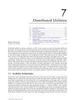
Distributed utilities (sometimes referred to as DU) is the current term used in describing distributed
generation and storage devices operating separately and in parallel with the utility grid. In most cases,
these devices are small in comparison to traditional utility base or peaking generation, but can range up to
several megawatts. For the purposes of this section, DU will be limited to devices 5 MWand below applied
at either the secondary voltage level, 120 V single phase to 480 V three phase, and at the medium voltage
level, 2.4 kV to 25 kV, although many of the issues discussed would apply to the larger units as well.
In this section, we will give an overview of the different issues associated with DU, including available
technologies, interfacing, a short discussion on economics and possible regulatory treatment, appli-
cations, and some practical examples. Emerging technologies discussed will include fuel cells, micro-
turbines, and small turbines. A brief discussion of storage technologies is also included. Interfacing
issues include general protection, overcurrent protection, islanding issues, communication and control,
voltage regulation, frequency control, fault detection, safety issues, and synchronization. In the appli-
cations section, deferred investment, demand reduction, peak shaving, ancillary services, reliability, and
power quality will be discussed. Economics and possible regulatory treatment will be discussed briefly.
7.1 Available Technologies
Many of the ‘‘new’’ technologies have been around for several years, but the relative cost per kilowatt of
small generators compared to conventional power plants has made their use limited. Utility rules and
interconnect requirements have also limited the use of small generators and storage devices to mostly
emergency, standby, and power quality applications. The prospect of deregulation has changed all that.
Utilities are no longer assured that they can recover the costs of large base generation plants, and
stranded investment of transmission and distribution facilities is a subject of debate. This, coupled
with improvements in the cost and reliability of DU technologies, has opened an emerging market for
small power plants. In the near future, these new technologies should be competitive with conventional
plants, providing high reliability with less investment risk. Some of the technologies are listed below. All
of the energy storage devices and many of the small emerging generation devices are inverter=converter
ß 2006 by Taylor & Francis Group, LLC.
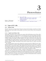
based. Figure 7.1 is a listing of different technologies, their size ranges, fuel sources, and AC interface
type, and most likely applications.
7.2 Fuel Cells
Fuel cell technology has been around since its invention by William Grove in 1839. From the 1960s to
the present, fuel cells have been the power source used for space flight missions. Unlike other generation
technologies, fuel cells act like continuously fueled batteries, producing direct current (DC) by using
an electrochemical process. The basic design of all fuel cells consists of an anode, electrolyte, and
cathode. Hydrogen or a hydrogen-rich fuel gas is passed over the anode, and oxygen or air is passed
over the cathode. A chemical combination then takes place producing a constant supply of electrons
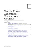
(DC current) with by-products of water, carbon dioxide, and heat. The DC power can be used directly or
it can be fed to a power conditioner and converted to AC power (see Fig. 7.2).
Technology Size Fuel Sources AC Interface Type Applications
Fuel Cells
Microturbines
Batteries
Flywheel
PV
Gas Turbine
.5Kw–
Larger units
With Stacking
10Kw-100Kw
Larger sizes
.1Kw-2Mw+
>.1Kw 5Kw
>.1Kw-1Kw
10Kw–5Mw+
Natural Gas
Hydrogen
Petroleum Products
Inverter type Continuous
Continuous
Standby
PQ, Peaking
PQ, Peaking
Peaking
Continuous,
Peaking
Standby
Inverter type
Inverter type
Inverter type
Inverter type
Rotary type
Natural Gas
Petroleum Products
Storage
Storage
Sunlight
Natural Gas
Petroleum Products
FIGURE 7.1 Distributed generation technology chart.
Hydrogen (H
2
)
H
2
O, CO
2
and Heat
DC Current Flow
Air (O
2
, CO
2
)
anode
Electrons
cathode
electrolyte
FIGURE 7.2 Basic fuel cell operation.
ß 2006 by Taylor & Francis Group, LLC.
Most of the present technologies have a fuel reformer or processor that can take most hydrocarbon-
based fuels, separate out the hydrogen, and produce high-quality power with negligible emissions. This
would include gasoline, natural gas, coal, methanol, light oil, or even landfill gas. In addition, fuel cells
can be more efficient than conventional generators. Theoretically they can obtain efficiencies as high as
85% when the excess heat produced in the reaction is used in a combined cycle mode. These features,
along with relative size and weight, have also made the fuel cell attractive to the automotive industry as
an alternative to battery power for electric vehicles. The major differences in fuel cell technology concern
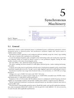
the electrolyte composition. The major types are the Proton Exchange Membrane Fuel Cell (PEFC) also
called the PEM, the Phosphoric Acid Fuel Cell (PAFC), the Molten Carbonate Fuel Cell (MCFC), and the
Solid Oxide Fuel Cell (SOFC) (Fig. 7.3).
Fuel cell power plants can come in sizes ranging from a few watts to several megawatts with stacking.
The main disadvantage to the fuel cell is the initial high cost of installation. With the interest in
efficient and environmentally friendly generation, coupled with the automotive interest in an EV
alternative power source, improvements in the technology and lower costs are expected. As with all
new technologies, volume of sales should also lower the unit price.
7.3 Microturbines
Experiments with microturbine technology have been around for many decades, with the earliest
attempts of wide-scale applications being targeted at the automotive and transportation markets.
These experiments later expanded into markets associated with military and commercial aircraft and
mobile systems. Microturbines are typically defined as systems with an output power rating of between
10 kW up to a few hundred kilowatts. As shown in Fig. 7.4, these systems are usually a single-shaft
design with compressor, turbine, and generator all on the common shaft, although some companies are
engineering dual-shaft systems. Like the large combustion turbines, the microturbines are Brayton Cycle
systems, and will usually have a recuperator in the system.
The recuperator is incorporated as a means of increasing efficiency by taking the hot turbine exhaust
through a heavy (and relatively expensive) metallic heat exchanger and transferring the heat to the input
air, which is also passed through parallel ducts of the recuperator. This increase in inlet air temperature
helps reduce the amount of fuel needed to raise the temperature of the gaseous mixture during
combustion to levels required for total expansion in the turbine. A recuperated Brayton Cycle micro-
turbine can operate at efficiencies of approximately 30%, while these aeroderivative systems operating
without a recuperator would have efficiencies in the mid-teens.
PAFC MCFC SOFC PEMFC
Electrolyte
Operating Temperature
Fuels
Reforming
Oxidant
Efficiency (HHV)
Phosphoric acid
Reformate
External
O
2
/Air O
2
/Air O
2
/Air
40−50% 50−60% 45−55% 40−50%
CO
2
/O
2
/Air
External External External
Reformate Reformate Reformate
375ЊF (190ЊC)
Hydrogen (H
2
)H
2
/CO H
2
/CO
2
/CH
4
H
2
1200ЊF (650ЊC) 1830ЊF (1000ЊC) 175ЊF (80ЊC)
Molten carbonate salt Ceramic Polymer
FIGURE 7.3 Comparison of fuel cell types. (From DoD Website, www.dodfuelcell.com=fcdescriptions.html.)
ß 2006 by Taylor & Francis Group, LLC.
Another requirement of microturbine systems is that the shaft must spin at very high speeds, in
excess of 50,000 RPM and in some cases doubling that rate, due to the low inertia of the shaft and
connected components. This high speed is used to keep the weight of the system low and increase the
power density over other generating technologies. Although many of the microturbines are touted as
having only a single moving part, there are numerous ancillary devices required that do incorporate
moving parts such as cooling fans, fuel compressors, and pumps.
Since the turbine requires extremely high speeds for optimal performance, the generator cannot
operate as a synchronous generator. Typical microturbines have a permanent magnet motor=generator
incorporated onto the shaft of the system. The high rotational speed gives an AC output in excess of
1000 Hz, depending on the number of poles and actual rotational speed of the microturbine. This high-
frequency AC source is rectified, forming a common DC bus voltage that is then converted to a 60-Hz
AC output by an onboard inverter.
The onboard electronics are also used to start the microturbine, either in a stand-alone mode or in
grid parallel applications. Typically, the utility voltage will be rectified and the electronics are used to
convert this DC voltage into a variable frequency AC source. This variable frequency drive will power the
permanent magnet motor=generator (which is operating as a motor), and will ramp the turbine speed
up to a preset RPM, a point where stabile combustion and control can be maintained. Once this preset
speed is obtained and stabile combustion is taking place, the drive shuts down and the turbine speed
increases until the operating point is maintained and the system operates as a generator. The time from a
‘‘Shaft Stop’’ to full load condition is anywhere from 30 sec to 3 min, depending on manufacturer
recommendations and experiences.
Although things are in the early stages of commercialization of the microturbine products, there are
cost targets that have been announced from all of the major manufacturers of these products. The early
market entry price of these systems is in excess of $600 per kW, more than comparably sized units of
alternative generation technologies, but all of the major suppliers have indicated that costs will fall as the
number of units being put into the field increases.
The microturbine family has a very good environmental rating, due to natural gas being a primary
choice for fuel and the inherent operating characteristics, which puts these units at an advantage over
diesel generation systems.
Generator
Turbine
Fuel
Recuperator
Exhaust
Compressor
Air Intake
FIGURE 7.4 Turbine block diagram configuration with recuperator.
ß 2006 by Taylor & Francis Group, LLC.
7.4 Combustion Turbines
There are two basic types of combustion turbines (CTs) other than the microturbines: the
heavy frame industrial turbines and the aeroderivative turbines. The heavy frame systems are derived
from similar models that were steam turbine designs. As can be identified from the name, they are of
very heavy construction. The aeroderivative systems have a design history from the air flight industry,
and are of a much lighter and higher speed design. These types of turbines, although similar in
operation, do have some significant design differences in areas other than physical size. These include
areas such as turbine design, combustion areas, rotational speed, and air flows.
Although these units were not originally designed as a ‘‘distributed generation’’ technology, but more
so for central station and large co-generation applications, the technology is beginning to economically
produce units with ratings in the hundreds of kilowatts and single-digit megawatts. These turbines
operate as Brayton Cycle systems and are capable of operating with various fuel sources. Most
applications of the turbines as distributed generation will operate on either natural gas or fuel oil.
The operating characteristics between the two systems can best be described in tabular form as shown
in Fig. 7.5.
The combustion turbine unit consists of three major mechanical components: a compressor, a
combustor, and a turbine. The compressor takes the input air and compresses it, which will increase
the temperature and decrease the volume per the Brayton Cycle. The fuel is then added and the
combustion takes place in the combustor, which increases both the temperature and volume of
the gaseous mixture, but leaves the pressure as a constant. This gas is then expanded through the
turbine where the power is extracted through the decrease in pressure and temperature and the increase
in volume.
If efficiency is the driving concern, and the capital required for the increased efficiency is available,
the Brayton Cycle systems can have either co-generation systems, heat recovery steam generators, or
simple recuperators added to the combustion turbine unit. Other equipment modifications
and improvements can be incorporated into these types of combustion turbines such as multis-
tage turbines with fuel re-injection, inter-cooler between multistage compressors, and steam=water
injection.
Typical heat rates for simple cycle combustion turbines vary across manufacturers, but are in a
range from 11,000 to 20,000 BTU=kWh. However, these numbers decrease as recuperation and
co-generation are added. CTs typically have a starting reliability in the 99% range and operating
reliability approaching 98%. The operating environment has a major effect on the performance
of combustion turbines. The elevation at which the CT is operating has a degradation factor of
around 3.5% per 1000 ft of increased elevation and the ambient temperature has a similar degradation
per 108 increase.
Figure 7.6 shows a block diagram of a simple cycle combustion turbine with a recuperator (left) and a
combustion turbine with multistage turbine and fuel re-injection (right).
Size (Same General Rating)
Heavy Frame
Aeroderivative
Compact
Higher Speed (coupled
through a gear box)
Lower (high compression)
2-3 minutes
Large
Synchronous
High (lower compression)
15 Minutes
Shaft Speed
Air Flow
Start-up Time
FIGURE 7.5 Basic combustion turbine operating characteristics.
ß 2006 by Taylor & Francis Group, LLC.
7.5 Storage Technologies
Storage technologies include batteries, flywheels, ultra-capacitors, and to some extent photovoltaics.
Most of these technologies are best suited for power quality and reliability enhancement applications,
due to their relative energy storage capabilities and power density characteristics, although some large
battery installations could be used for peak shaving. All of the storage technologies have a power
electronic converter interface and can be used in conjunction with other DU technologies to provide
‘‘seamless’’ transitions when power quality is a requirement.
7.6 Interface Issues
A whole chapter could be written just about interface issues, but this discussion will touch on the
highlights. Most of the issues revolve around safety and quality of service. We will discuss some general
guidelines and the general utility requirements and include examples of different considerations. In
addition to the interface issues, the DU installation must also provide self-protection to prevent short
circuit or other damage to the unit. Self-protection will not be discussed here. The most important issues
are listed in Table 7.1.
In addition to the interface issues identified in Table 7.1, there are also operating limits that must be
considered. These are listed in Table 7.2.
Generator
Recuperator
Fuel
Fuel Fuel
Turbine
Exhaust
exhaust
Compressor
Turbine Turbine
Compressor
Generator
Air Intake
Air Intake
FIGURE 7.6 Basic combustion turbine designs.
TABLE 7.1 Interface Issues
Issue Definition Concern
Automatic reclosing Utility circuit breakers can test the
line after a fault.
If a generator is still connected to the
system, it may not be in synchronization,
thus damaging the generator or causing
another trip.
Faults Short circuit condition on the utility system. Generator may contribute additional
current to the fault, causing a miss
operation of relay equipment.
Islanding A condition where a portion of the system
continues to operate isolated from
the utility system.
Power quality, safety, and protection
may be compromised in addition to
possible synchronization problems.
Protection Relays, instrument transformers, circuit breakers. Devices must be utility grade rather
than industrial grade for better accuracy.
Devices must also be maintained on a
regular schedule by trained technicians.
Communication Devices necessary for utility control during
emergency conditions.
Without control of the devices, islanding
and other undesirable operation of devices.
ß 2006 by Taylor & Francis Group, LLC.
Utility requirements vary but generally depend on the application of a distributed source. If the unit is
being used strictly for emergency operation, open transition peak shaving, or any other stand-alone type
operation, the interface requirements are usually fairly simple, since the units will not be operating in
parallel with the utility system. When parallel operation is anticipated or required, the interface
requirements become more complex. Protection, safety, power quality, and system coordination become
issues that must be addressed. In the case of parallel operation, there are generally three major factors
that determine the degree of protection required. These would include the size and type of the
generation, the location on the system, and how the installation will operate (one-way vs. two-way).
Generator sizes are generally classified as:
Large: Greater than 3 MVA or possibility of ‘‘islanding’’ a portion of the system
Small: Between large and extremely small
Extremely small: Generation less than 100 kVA
Location on the system and individual system characteristics determine impedance of a distribution
line, which in turn determines the available fault current and other load characteristics that influence
‘‘islanding’’ and make circuit protection an issue. This will be discussed in more detail later.
The type of operation is the other main issue and is one of the main determinants in the amount of
protection required. One-way power flow where power will not flow back into the utility has a fairly
simple interface, but is dependent on the other two factors, while two-way interfaces can be quite
complex. An example is shown in Fig. 7.7. Smaller generators and ‘‘line-commutated’’ units would have
less stringent requirements. Commutation methods will be discussed later. Reciprocating engines such
as diesel and turbines with mass, and ‘‘self-commutating’’ units which could include microturbines
and fuel cells, would require more stringent control packages due to their islanding and reverse
power capabilities.
Most of the new developing technologies are inverter based and there are efforts now in IEEE to revise
the old Standard P929 Recommended Practice for Utility Interface of Photovoltaic (PV) Systems to include
other inverter-based devices. The standards committee is looking at the issues with inverter-based
devices in an effort to develop a standard interface design that will simplify and reduce the cost, while
not sacrificing the safety and operational concerns. Inverter interfaces generally fall into two classes: line-
commutated inverters and self-commutated inverters.
7.6.1 Line-Commutated Inverters
These inverters require a switching signal from the line voltage in order to operate. Therefore, they will
cease operation if the line signal, i.e., utility voltage, is abnormal or interrupted. These are not as popular
today for single-phase devices due to the filtering elements required to meet the harmonic distortion
requirements, but are appearing in some of the three-phase devices where phase cancellation minimizes
the use of the additional components.
TABLE 7.2 Operating Limits
1. Voltage—The operating range for voltage must maintain a level of +15% of nominal for service voltage
(ANSI C84.1), and have a means of automatic separation if the level gets out of the acceptable range within a
specified time.
2. Flicker—Flicker must be within the limits as specified by the connecting utility. Methods of controlling flicker
are discussed in IEEE Std. 519-1992, 10.5.
3. Frequency—Frequency must be maintained within +0.5 Hz of 60 Hz and have an automatic means of
disconnecting if this is not maintained. If the system is small and isolated, there might be a larger frequency
window. Larger units may require an adjustable frequency range to allow for clock synchronizaton.
4. Power factor—The power factor should be within 0.85 lagging or leading for normal operation. Some systems that
are designed for compensation may operate outside these limits.
5. Harmonics—Both voltage and current harmonics must comply with the values for generators as specified in
IEEE Std. 519-1992 for both total and individual harmonics.
ß 2006 by Taylor & Francis Group, LLC.
7.6.2 Self-Commutated Inverters
These inverters, as implied by the name, are self-commutating. All stand-alone units are self-
commutated, but not all self-commutated inverters are stand-alone. They can be designed as either
voltage or current sources and most that are now being designed to be connected to the utility system are
designed to be current sources. These units still use the utility voltage signal as a comparison and
produce current at that voltage and frequency. A great deal of effort has gone into the development of
non-islanding inverters that are of this type.
7.7 Applications
Applications vary and will become more diverse as utilities unbundle. Listed below are some examples of
the most likely.
7.7.1 Ancillary Services
Ancillary services support the basic electrical services and are essential for the reliability and operation of
the electric power system. The electrical services that are supported include generating capacity, energy
supply, and the power delivery system. FERC requires six ancillary services, including system control,
regulation (frequency), contingency reserves (both spinning and supplemental), voltage control, and
energy imbalance. In addition, load following, backup supply, network stability, system ‘‘black-start’’,
loss replacement, and dynamic scheduling are necessary for the operation of the system. Utilities
have been performing these functions for decades, but as vertically integrated regulated monopoly
∗
∗
Relays trip Breaker/Recloser A.
Breaker A may reclose only if
utility source is hot and NUG
bus is dead.
NUG
Load
Utility
B
C
G
A
M
Device No.
59/27 Overvoltage/Undervoltage
Over/Underfrequency
Zero Sequence Overvoltage
Phase Overcurrent
Ground Overcurrent
81
59G
50/51
50/51N
Function
Reclose if NUG bus is
dead and utility
source is hot
Breaker
or 3 phase OCR
Meter
1 PT
Voltage check
3 PT's
FIGURE 7.7 Example of large generator interface requirements for distribution. (From Georgia Power Bulletin,
18–8, generator interface requirements.)
ß 2006 by Taylor & Francis Group, LLC.
organizations. As these begin to disappear, and a new structure with multiple competing parties
emerges, distributed utilities might be able to supply several of these.
The distributed utilities providing these services could be owned by the former traditional utility,
customers, or third-party brokers, depending on the application. The main obstacles to this approach
are aggregation and communication when dealing with many small resources rather than large central
station sources.
7.7.2 ‘‘Traditional Utility’’ Applications
Traditional utilities may find the use of DU a practical way to solve loading and reliability problems if each
case is evaluated on a stand-alone individual basis. Deferring investment is one likely way that DU can be
applied. In many areas, substations and lines have seasonal peaks that are substantially higher than the rest of
the year. In these cases, the traditional approach has been to increase the capacity to meet the demand. Based
on the individual situation, delaying the upgrade for 2 to 5 years with a DU system could be a more
economical solution. This would be especially true if different areas had different seasonal peaks and the DU
system was portable, thus deferring two upgrades. DU could also be used instead of conventional facilities
when backup feeds are required or to improve reliability or power quality.
In addition, peak shaving and generation reserve could be provided with strategically placed DU
systems that take advantage of reducing system losses as well as offsetting base generation. Again, these
have to be evaluated on an individual case basis and not a system average basis as is done in many
economic studies. The type of technology used will depend on the particular requirements. In general,
storage devices such as flywheels and batteries are better for power quality applications due to their
fast response time, in many cases half a cycle. Generation devices are better suited for applications
that require more than 30 min of supply, such as backup systems, alternate feeds, peak shaving,
and demand deferrals. Generation sources can also be used instead of conventional facilities in
certain cases.
7.7.3 Customer Applications
Individual customers with special requirements may find DU technologies that meet their
needs. Customers who require ‘‘enhanced’’ power quality and reliability of service already utilize UPS
systems with battery backup to condition the power to sensitive equipment, and many hospitals, waste
treatment plants, and other emergency services providers have emergency backup systems supplied
by standby generator systems. As barriers go down and technologies improve, customer-sited DU
facilities could provide many of the ancillary services as well as sell excess power into the grid. Fuel
cell and even diesel generators could be especially attractive for customers with requirements of heat and
steam. Many of the fuel cell technologies are now looking at the residential market with small units that
would be connected to the grid but supply the additional requirements for customers with special power
quality needs.
7.7.4 Third-Party Service Providers
Third-party service providers could provide all the services listed above for the utilities and customers,
in addition to selling power across the grid. In many cases, an end user does not have the expertise to
operate and maintain generation systems and would prefer to purchase the services.
7.8 Conclusions
Disbursed generation will be a part of the distribution utility system of the future. Economics, regulatory
requirements, and technology improvements will determine the speed at which they are integrated.
ß 2006 by Taylor & Francis Group, LLC.
References
ANSI=IEEE Std. 1001–1998, IEEE Guide for Interfacing Dispersed Storage and Generation Facilities with
Electric Utility Systems, IEEE Standards Coordinating Committee 23, Feb. 9, 1989.
Davis, M.W. Microturbines—An Economic and Reliability Evaluation for Commercial, Residential, and
Remote Load Applications, IEEE Transactions PE-480-PWRS-0-10-1998.
Delmerico, R.W., Miller, N.W., and Owen, E.L. Power System Integration Strategies for Distributed
Generation, Power Systems Energy Consulting GE International, Inc., Distributed Electricity
Generation Conference, Denver, CO, Jan. 25, 1999.
Department of Defense Website, www.dodfuelcell.com=fcdescriptions.html.
Goldstein, H.L. Small Turbines in Distributed Utility Application Natural Gas Pressure Supply
Requirements, NREL=SP-461-21073, May, 1996.
Hirschenhofer, J.H. DOE Forum on Fuel Cell Technologies, IEEE Winter Power Meeting, Parsons
Corporation Presentation, Feb. 4, 1999.
Kirby, B. Distributed Generation: A Natural for Ancillary Services, Distributed Electric Generation
Conference, Denver CO, Jan. 25, 1999.
Oplinger, J.L. Methodology to Assess the Market Potential of Distributed Generation, Power Systems Energy
Consulting GE International, Inc., Distributed Electric Generation Conference, Denver, CO,
Jan. 25, 1999.
Recommended Practice for Utility Interface of Photovoltaic (PV) Systems, IEEE Standard P929, Draft 10,
Feb. 1999.
Southern Company Parallel Operation Requirements, Protection and Control Committee, Aug. 4, 1998.
Technology Overviews, DOE Forum on Fuel Cell Technology, IEEE Winter Power Meeting, Feb. 4, 1999.
ß 2006 by Taylor & Francis Group, LLC.