power system stability and control chuong (10)
Bạn đang xem bản rút gọn của tài liệu. Xem và tải ngay bản đầy đủ của tài liệu tại đây (948.54 KB, 14 trang )
III
Transmission
System
George G. Karady
Arizona State University
8 Concept of Energy Transmission and Distribution George G. Karady 8-1
Generation Stations
.
Switchgear
.
Control Devices
.
Concept of
Energy Transmission and Distribution
9 Transmission Line Structures Joe C. Pohlman 9-1
Traditional Line Design Practice
.
Current Deterministic Design Practice
.
Improved Design Approaches
.
Appendix A General Design
Criteria—Methodology
10 Insulators and Accessories George G. Karady and Richard G. Farmer 10-1
Electrical Stresses on External Insulation
.
Ceramic (Porcelain and Glass)
Insulators
.
Nonceramic (Composite) Insulators
.
Insulator Failure
Mechanism
.
Methods for Improving Insulator Performance
11 Transmission Line Construction and Maintenance Wilford Caulkins
and Kristine Buchholz 11-1
Tools
.
Equipment
.
Procedures
.
Helicopters
12 Insulated Power Cables Used in Underground Applications Michael L. Dyer 12-1
Underground System Designs
.
Conductor
.
Insulation
.
Medium- and
High-Voltage Power Cables
.
Shield Bonding Practice
.
Installation Practice
.
System Protection Devices
.
Common Calculations used with Cable
13 Transmission Line Parameters Manuel Reta-Herna
´
ndez 13-1
Equivalent Circuit
.
Resistance
.
Current-Carrying Capacity (Ampacity)
.
Inductance and Inductive Reactance
.
Capacitance and Capacitive Reactance
.
Characteristics of Overhead Conductors
14 Sag and Tension of Conductor D.A. Douglass and Ridley Thrash 14-1
Catenary Cables
.
Approximate Sag-Tension Calculations
.
Numerical
Sag-Tension Calculations
.
Ruling Span Concept
.
Line Design
Sag-Tension Parameters
.
Conductor Installation
.
Defining Terms
ß 2006 by Taylor & Francis Group, LLC.
15 Corona and Noise Giao N. Trinh 15-1
Corona Modes
.
Main Effects of Corona Discharges on Overhead Lines
.
Impact on the Selection of Line Conductors
.
Conclusions
16 Geomagnetic Disturbances and Impacts upon Power System Operation
John G. Kappenman 16-1
Introduction
.
Power Grid Damage and Restoration Concerns
.
Weak Link
in the Grid: Transformers
.
An Overview of Power System Reliability and
Related Space Weather Climatology
.
Geological Risk Factors and Geoelectric
Field Response
.
Power Grid Design and Network Topology Risk Factors
.
Extreme Geomagnetic Disturbance Events—Observational Evidence
.
Power Grid Simulations for Extreme Disturbance Events
.
Conclusions
17 Lightning Protection William A. Chisholm 17-1
Ground Flash Density
.
Stroke Incidence to Power Lines
.
Stroke
Current Parameters
.
Calculation of Lightning Overvoltages on
Shielded Lines
.
Insulation Strength
.
Mitigation Methods
.
Conclusion
18 Reactive Power Compensation Rao S. Thallam 18-1
The Need for Reactive Power Compensation
.
Application of Shunt Capacitor
Banks in Distribution Systems—A Utility Perspective
.
Static VAR Control
.
Series Compensation
.
Series Capacitor Bank
.
Defining Terms
19 Environmental Impact of Transmission Lines George G. Karady 19-1
Introduction
.
Aesthetical Effects of Lines
.
Magnetic Field Generated
by HV Lines
.
Electrical Field Generated by HV Lines
.
Audible Noise
.
Electromagnetic Interference
ß 2006 by Taylor & Francis Group, LLC.
8
Concept of Energy
Transmission and
Distribution
George G. Karady
Arizona State University
8.1 Generation Stations 8-1
8.2 Switchgear 8-3
8.3 Control Devices 8-4
8.4 Concept of Energy Transmission and Distribution 8-4
High-Voltage Transmission Lines
.
High-Voltage DC Lines
.
Sub-Transmission Lines
.
Distribution Lines
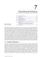
The purpose of the electric transmission system is the interconnection of the electric energy producing
power plants or generating stations with the loads. A three-phase AC system is used for most transmis-
sion lines. The operating frequency is 60 Hz in the U.S. and 50 Hz in Europe, Australia, and part of Asia.
The three-phase system has three phase conductors. The system voltage is defined as the rms voltage
between the conductors, also called line-to-line voltage. The voltage between the phase conductor and
ground, called line-to-ground voltage, is equal to the line-to-line voltage divided by the square root of
three. Figure 8.1 shows a typical system.
The figure shows the Phoenix area 230-kV system, which interconnects the local power plants and the
substations supplying different areas of the city. The circles are the substations and the squares are the
generating stations. The system contains loops that assure that each load substation is supplied by at
least two lines. This assures that the outage of a single line does not cause loss of power to any customer.
For example, the Aqua Fria generating station (marked: Power plant) has three outgoing lines. Three
high-voltage cables supply the Country Club Substation (marked: Substation with cables). The Pinnacle
Peak Substation (marked: Substation with transmission lines) is a terminal for six transmission lines.
This example shows that the substations are the node points of the electric system. The system is
interconnected with the neighboring systems. As an example, one line goes to Glen Canyon and the
other to Cholla from the Pinnacle Peak substation.
In the middle of the system, which is in a congested urban area, high-voltage cables are used. In open
areas, overhead transmission lines are used. The cost per mile of overhead transmission lines is 6 to 10%
less than underground cables.
The major components of the electric system, the transmission lines, and cables are described
briefly below [1].
8.1 Generation Stations
The generating station converts the stored energy of gas, oil, coal, nuclear fuel, or water position to
electric energy. The most frequently used power plants are:
ß 2006 by Taylor & Francis Group, LLC.
To Mead
Palo Verde
and
Navajo
Westwing
Surprise
EL Sol
AQUA FRIA
GLENDALE
WEST
PHOENIX
1-10 FWY.
1-10 FWY.
Substation
with cables
230KV SUBSTATION
EHV LINES
230KV LINES
OVERHEAD
UNDERGROUND
GENERATING SITE &
230KV SUBSTATION
JOINT OWNSHIP
OTHER COMPANIES
'
LINES
Power
plant
Deer Valley
SRP
SRP
SRP
HVA KV.
APS
APS
TO
CLEN CANYON
(WAPA)
TO CHOLLA
J/O APS/SRP
SRP
Lone Peak
Alexender
COUNTRY
CLUB
Pinnacle Peak
Cactus
BETHANY
HOME RD.
Gliber
OCOTILLO
TO PALO VERDE
500KV
TO SILVERKING
500KV
TO
SANTA ROSA
KYRENE
SUPERSTITION FWY.
BASELINE RD.
Major substation with
transmission lines
1-17 FWY
APS
APS
PHOENIX AREA
130KV TRANSMISSION SYSTEM
APS
SRP
BELL RD.
BELL RD.
BASELINE RD.
LEGEND
SUNNYSl
MEADOWEROOK
WHITE TANKS (APS)
LINOOLN ST.
Litchfield Rd.
FIGURE 8.1 One line diagram of a high voltage electric transmission system.
ß 2006 by Taylor & Francis Group, LLC.
Thermal Power Plant. The fuel is pulverized coal or natural gas. Older plants may use oil. The fuel is mixed
with air and burned in a boiler that generates steam. The high-pressure and high-temperature steam
drives the turbine, which turns the generator that converts the mechanical energy to electric energy.
Nuclear Power Plant. Enriched uranium produces atomic fission that heats water and produces steam.
The steam drives the turbine and generator.
Hydro Power Plants. A dam increases the water level on a river, which produces fast water flow to drive
a hydro-turbine. The hydro-turbine drives a generator that produces electric energy.
Gas Turbine. Natural gas is mixed with air and burned. This generates a high-speed gas flow that
drives the turbine, which turns the generator.
Combined Cycle Power Plant. This plant contains a gas turbine that generates electricity. The exhaust
from the gas turbine is high-temperature gas. The gas supplies a heat exchanger to preheat the
combustion air to the boiler of a thermal power plant. This process increases the efficiency of the
combined cycle power plant. The steam drives a second turbine, which drives the second generator.
This two-stage operation increases the efficiency of the plant.
8.2 Switchgear
The safe operation of the system requires switches to open lines automatically in case of a fault, or
manually when the operation requires it. Figure 8.2 shows the simplified connection diagram of a
generating station.
The generator is connected directly to the low-voltage winding of the main transformer. The trans-
former high-voltage winding is connected to the bus through a circuit breaker, disconnect switch, and
current transformer. The generating station auxiliary power is supplied through an auxiliary transformer
through a circuit breaker, disconnect switch, and current transformer. Generator circuit breakers, con-
nected between the generator and transformer, are frequently used in Europe. These breakers have to
interrupt the very large short-circuit current of the generators, which results in high cost.
The high-voltage bus supplies two outgoing lines. The station is protected from lightning and
switching surges by a surge arrester.
Circuit breaker (CB) is a large switch that interrupts the load and fault current. Fault detection systems
automatically open the CB, but it can be operated manually.
Disconnect switch provides visible circuit separation and permits CB maintenance. It can be operated
only when the CB is open, in no-load condition.
Auxiliary transformer
Main transformer
Generator
Disconnect switch
Current transformer
Circuit breaker
Surge
arrester
Voltage transformer
FIGURE 8.2 Simplified connection diagram of a generating station.
8-3
ß 2006 by Taylor & Francis Group, LLC.
Potential transformers (PT) and current transformers (CT) reduce the voltage to 120 V, the current to
5 A, and insulates the low-voltage circuit from the high-voltage. These quantities are used for metering
and protective relays. The relays operate the appropriate CB in case of a fault.
Surge arresters are used for protection against lightning and switching overvoltages. They are voltage
dependent, nonlinear resistors.
8.3 Control Devices
In an electric system the voltage and current can be controlled. The voltage control uses
parallel connected devices, while the flow or current control requires devices connected in series
with the lines.
Tap-changing transformers are frequently used to control the voltage. In this system, the turns-ratio of
the transformer is regulated, which controls the voltage on the secondary side. The ordinary tap changer
uses a mechanical switch. A thyristor-controlled tap changer has recently been introduced.
A shunt capacitor connected in parallel with the system through a switch is the most frequently used
voltage control method. The capacitor reduces lagging-power-factor reactive power and improves the
power factor. This increases voltage and reduces current and losses. Mechanical and thyristor switches
are used to insert or remove the capacitor banks.
The frequently used Static Var Compensator (SVC) consists of a switched capacitor bank and a
thyristor-controlled inductance. This permits continuous regulation of reactive power.
The current of a line can be controlled by a capacitor connected in series with the line. The capacitor
reduces the inductance between the sending and receiving points of the line. The lower inductance
increases the line current if a parallel path is available.
In recent years, electronically controlled series compensators have been installed in a few transmission
lines. This compensator is connected in series with the line, and consists of several thyristor-controlled
capacitors in series or parallel, and may include thyristor-controlled inductors.
Medium- and low-voltage systems use several other electronic control devices. The last part in this
section gives an outline of the electronic control of the system.
8.4 Concept of Energy Transmission and Distribution
Figure 8.3 shows the concept of typical energy transmission and distribution systems. The generating
station produces the electric energy. The generator voltage is around 15 to 25 kV. This relatively low
voltage is not appropriate for the transmission of energy over long distances. At the generating station a
transformer is used to increase the voltage and reduce the current. In Fig. 8.3 the voltage is increased to
500 kV and an extra-high-voltage (EHV) line transmits the generator-produced energy to a distant
substation. Such substations are located on the outskirts of large cities or in the center of several large
loads. As an example, in Arizona, a 500-kV transmission line connects the Palo Verde Nuclear Station to
the Kyrene and Westwing substations, which supply a large part of the city of Phoenix.
The voltage is reduced at the 500 kV=220 kV EHV substation to the high-voltage level and high-
voltage lines transmit the energy to high-voltage substations located within cities.
At the high-voltage substation the voltage is reduced to 69 kV. Sub-transmission lines connect the
high-voltage substation to many local distribution stations located within cities. Sub-transmission lines
are frequently located along major streets [2,3].
The voltage is reduced to 12 kV at the distribution substation. Several distribution lines emanate
from each distribution substation as overhead or underground lines. Distribution lines distribute the
energy along streets and alleys. Each line supplies several step-down transformers distributed along
the line. The distribution transformer reduces the voltage to 230=115 V, which supplies houses,
shopping centers, and other local loads. The large industrial plants and factories are supplied directly
by a subtransmission line or a dedicated distribution line as shown in Fig. 8.3.
ß 2006 by Taylor & Francis Group, LLC.
The overhead transmission lines are used in open areas such as interconnections between cities
or along wide roads within the cit y. In congested areas within cities, underground cables are used
for electric energy transmission. The underground transmission system is environmentally preferable
but has a significantly higher cost. In Fig. 8.3 the 12-kV line is connected to a 12-kV cable which
supplies commercial or industrial customers [4]. The figure also shows 12-kV cable networks supplying
downtown areas in a large city. Most newly developed residential areas are supplied by 12-kV cables
through pad-mounted step-down transformers as shown in Fig. 8.3.
8.4.1 High-Voltage Transmission Lines
Highvoltage and extra-high-voltage (EHV) transmission lines interconnect power plants and loads, and
form an electric network. Figure 8.4 shows a typical high-voltage and EHV system.
This system contains 500-kV, 345-kV, 230-kV, and 115-kV lines. The figure also shows that the
Arizona (AZ) system is interconnected with transmission systems in California, Utah, and New Mexico.
These interconnections provide instantaneous help in case of lost generation in the AZ system. This also
permits the export or import of energy, depending on the needs of the areas.
Presently, synchronous ties (AC lines) interconnect all networks in the eastern U.S. and Canada.
Synchronous ties also (AC lines) interconnect all networks in the western U.S. and Canada. Several
non-synchronous ties (DC lines) connect the East and the West. These interconnections increase the
reliability of the electric supply systems.
In the U.S., the nominal voltage of the high-voltage lines is between 100 kVand 230 kV. The voltage of
the extra-high-voltage lines is above 230 kV and below 800 kV. The voltage of an ultra-high-voltage line
is above 800 kV. The maximum length of high-voltage lines is around 200 miles. Extra-high-voltage
transmission lines generally supply energy up to 400–500 miles without intermediate switching and var
support. Transmission lines are terminated at the bus of a substation.
The physical arrangement of most extra-high-voltage (EHV) lines is similar. Figure 8.5 shows the
major components of an EHV, which are:
1. Tower: The figure shows a lattice, steel tower.
2. Insulator: V strings hold four bundled conductors in each phase.
3. Conductor: Each conductor is stranded, steel reinforced aluminum cable.
POWER PLANT
12KV COMMERCIAL or
INDUSTRIAL CUSTOMER
DOWNTOWN
NETWORK
69/12KV SUBSTATION
69KV SUBTRANSMISSION
230/69KV SUBSTATION
TO 230KV
SUBSTATION
12KV DISTRIBUTION
OVERHEAD 12KV
DISTRIBUTION
TRANSFORMER
RESIDENTIAL
CUSTOMER
UNDERGROUND 12KV
DISTRIBUTION
TRANSFORMER
RESIDENTIAL
CUSTOMER
12KV
DISTRIBUTION
500KV
TRANSMISSION
TO 230KV
SUBSTATION
500/230KV SUBSTATION
TRANSMISSION
230KV
TRANSMISSION
GENERATION
DISTRIBUTION
FIGURE 8.3 Concept of electric energy transmission.
ß 2006 by Taylor & Francis Group, LLC.
4. Foundation and grounding: Steel-reinforced concrete foundation and grounding electrodes
placed in the ground.
5. Shield conductors: Two grounded shield conductors protect the phase conductors from lightning.
At lower voltages the appearance of lines can be improved by using more aesthetically pleasing steel
tubular towers. Steel tubular towers are made out of a tapered steel tube equipped with banded arms.
The arms hold the insulators and the conductors. Figure 8.6 shows typical 230-kV steel tubular and
lattice double-circuit towers. Both lines carry two three-phase circuits and are built with two conductor
bundles to reduce corona and radio and TV noise. Grounded shield conductors protect the phase
conductors from lightning [1].
8.4.2 High-Voltage DC Lines
High-voltage DC lines are used to transmit large amounts of energy over long distances or through
waterways. One of the best known is the Pacific HVDC Intertie, which interconnects southern California
with Oregon. Another DC system is the +400 kV Coal Creek-Dickenson lines. Another famous HVDC
system is the interconnection between England and France, which uses underwater cables. In Canada,
Vancouver Island is supplied through a DC cable.
In an HVDC system the AC voltage is rectified and a DC line transmits the energy. At the end
of the line an inverter converts the DC voltage to AC. A typical example is the Pacific HVDC Intertie
that operates with +500 kV voltage and interconnects Southern California with the hydro stations
in Oregon.
APS Transmission System
Four
Corners
Salt Lake
Denver
Albuquerque
N.GILA
San Diego
Los Angeles
Los Angeles
J/o
Navajo
J/O
500KV J/O
500KV J/O
Seligman
Round Valley
Willow
Lake
Palo
Verde
Liberty
Pinnacle
Peak
Buckeye
Gila Bend
Vista
Kyrene
Casa Grande
San Manuel
Adams
Mural
Tatmemoli
Oracle
Junction
Santa
Rosa
Bagdad
Verde
Yavapai
Preacher
Canyon
Cholla
Moenkopi
Coconino
LEGEND
500 kV
345 kV
230 kV
115 kV
JOINT OWNSHIP
COUNTY BOUNDARY
J/O
APS Control Area Ties
SRP
TEP
WAPA - Desert Southwest
WAPA - Rocky Mtn
LADWP
SCE
IID
PSNM
SDG&E
Pac
FIGURE 8.4 Typical high-voltage and EHV transmission system (Arizona Public Service, Phoenix area system).
ß 2006 by Taylor & Francis Group, LLC.
Figure 8.7 shows a guyed tower arrangement used on the Pacific HVDC Intertie. Four guy wires
balance the lattice tower. The tower carries a pair of two-conductor bundles supported by suspension
insulators.
8.4.3 Sub-Transmission Lines
Typical sub-transmission lines interconnect the high-voltage substations with distribution stations
within a city. The voltage of the subtransmission system is between 46 kV, 69 kV, and 115 kV. The
maximum length of sub-transmission lines is in the range of 50–60 miles. Most subtransmission lines
are located along streets and alleys. Figure 8.8 shows a typical sub-transmission system.
This system operates in a looped mode to enhance continuity of service. This arrangement assures
that the failure of a line will not interrupt the customer’s power.
Figure 8.9 shows a typical double-circuit sub-transmission line, with a wooden pole and post-type
insulators. Steel tube or concrete towers are also used. The line has a single conductor in each phase. Post
insulators hold the conductors without metal cross arms. One grounded shield conductor on the top of
the tower shields the phase conductors from lightning. The shield conductor is grounded at each tower.
Plate or vertical tube electrodes (ground rod) are used for grounding.
8.4.4 Distribution Lines
The distribution system is a radial system. Figure 8.10 shows the concept of a typical urban distribution
system. In this system a main three-phase feeder goes through the main street. Single-phase subfeeders
129'-3/4"
44'
7"
131'
0"
Shield Conductor
Insulator
Tower
Grounding
electrodes
Foundation
Bundle Conductor
(4 conductors)
FIGURE 8.5 Typical high-voltage transmission line. (From Fink, D.G. and Beaty, H.W., Standard Handbook for
Electrical Engineering, 11th ed., McGraw-Hill, New York, 1978.)
ß 2006 by Taylor & Francis Group, LLC.
FIGURE 8.6 Typical 230-kV constructions.
Insulator
Bundled
conductors
Guyed wire
FIGURE 8.7 HVDC tower arrangement. (From Fink, D.G. and Beaty, H.W., Standard Handbook for Electrical
Engineering, 11th ed., McGraw-Hill, New York, 1978.)
ß 2006 by Taylor & Francis Group, LLC.
23 KV
bus
962
3142
2942
2742
762
562
962
462
262
762
1162
1862
230 KV
230 KV
662
1062
1462
1662
2062
LINE 2
OPEN
LINE 1
ENCANTO
FAULT
GARFIELD
transfer
362
162
69KV
INDIANOLA (IN)
ORANGEWOOD (OR)
12.47KV
1162
SHAW
762
1062
SUNNY SLOPE (ss)
COUNTRY CLUB (CC)
53
52
51
162
662
262
762
12.47KV
342
962
562
362
1062
MUMMY MTN
MEADOWBROOK (ME)
OCOTILLO
1362
562
962
162
762
JACKSON ST
HARBOR
TWENTY – THIRD ST
(TW)
RECORDER
FIGURE 8.8 Subtransmission system.
FIGURE 8.9 Typical subtransmission line.
ß 2006 by Taylor & Francis Group, LLC.
supply the crossroads. Secondary mains are supplied through transformers. The consumer’s service
drops supply the individual loads. The voltage of the distribution system is between 4.6 and 25 kV.
Distribution feeders can supply loads up to 20–30 miles.
Many distribution lines in the U.S. have been built with a wood pole and cross arm. The wood is
treated with an injection of creosote or other wood preservative that protects the wood from rotting and
termites. Most poles are buried in a hole without foundation. Lines built recently may use a simple
concrete block foundation. Small porcelain or non-ceramic, pin-type insulators support the conductors.
The insulator pin is grounded to eliminate leakage current, which can cause burning of the wood tower.
A simple vertical copper rod is used for grounding. Shield conductors are seldom used. Figure 8.11
shows typical distribution line arrangements.
Because of the lack of space in urban areas, distribution lines are often installed on the subtransmis-
sion line towers. This is referred to as underbuild. A typical arrangement is shown in Fig. 8.12.
Primary
consumer
Feed point
Distribution
transformer
First
consumer
Sectionalizing switches labeled s are normally closed
Emer
g
ency tie " " d " " open
Emergency tie
to other feeder
Subfeeder
Lateral feeder
Subfeeder
x
x
Subfeeder
Feeder circuit
breaker
substation busDistribution
Energy
subtransmission
from
system
Feeder
s
s
2
8
5
d
2
d
1
d
d
d
346
7
s
s
3
s
5
s
4
s
s
s
s
2
s
Crosslines indicate
number of conductors
Last
consumer
Emergency
tie
Secondary
main
Consumers
service drops
FIGURE 8.10 Concept of radial distribution system.
C
B
(a) Pole top (b) Two arm (c) Sin
g
le arm
BE
D
F
A
FIGURE 8.11 Distribution line arrangements.
ß 2006 by Taylor & Francis Group, LLC.
The figure shows that small porcelain insulators support the conductors. The insulators are installed
on metal brackets that are bolted onto the wood tower. This arrangement reduces the right-of-way
requirement and saves space.
FIGURE 8.12 Distribution line installed under the subtransmission line.
Fuse and disconnect
Distribution line 13.8 kV
Transformer
240/120 V line
Distribution Cable 13.8 kV
Telephone Line
FIGURE 8.13 Service drop.
ß 2006 by Taylor & Francis Group, LLC.
Transformers mounted on distribution poles frequently supply individual houses or groups of houses.
Figure 8.13 shows a typical transformer pole, consisting of a transformer that supplies a 240=120-V
service drop, and a 13.8-kV distribution cable. The latter supplies a nearby shopping center, located on
the other side of the road. The 13.8-kV cable is protected by a cut-off switch that contains a fuse
mounted on a pivoted insulator. The lineman can disconnect the cable by pulling the cut-off open with a
long insulated rod (hot stick).
References
1. Electric Power Research Institute, Transmission Line Reference Book, 345 kV and Above, Electric Power
Research Institute, Palo Alto, CA, 1987.
2. Fink, D.G. and Beaty, H.W., Standard Handbook for Electrical Engineering, 11th ed., McGraw-Hill,
New York, Sec. 18, 1978.
3. Gonen, T., Electric Power Distribution System Engineering, Wiley, New York, 1986.
4. Gonen, T., Electric Power Transmission System Engineering, Wiley, New York, 1986.
ß 2006 by Taylor & Francis Group, LLC.