synchronous generators chuong (2)
Bạn đang xem bản rút gọn của tài liệu. Xem và tải ngay bản đầy đủ của tài liệu tại đây (1.3 MB, 29 trang )
© 2006 by Taylor & Francis Group, LLC
2-1
2
Principles of Electric
Generators
2.1 The Three Types of Electric Generators 2-1
2.2 Synchronous Generators
2-4
2.3 Permanent Magnet Synchronous Generators
2-8
2.4 The Homopolar Synchronous Generator
2-11
2.5 Induction Generator
2-13
2.6 The Wound Rotor (Doubly Fed) Induction
Generator (WRIG)
2-15
2.7 Parametric Generators
2-17
The Flux Reversal Generators • The Transverse Flux Generators
(TFGs) • Linear Motion Alternators
2.8 Electric Generator Applications 2-26
2.9 Summary
2-26
References
2-28
The extremely large power/unit span, from milliwatts to hundreds of megawatts (MW)
and more, and
the wide diversity of applications, from electric power plants to car alternators, should have led to
numerous electric generator configurations and controls. And, so it did. To bring order to our presen-
tation, we need some classifications.
2.1 The Three Types of Electric Generators
Electric generators may be classified many ways, but the following are deemed as fully representative:
• By principle
• By application domain
The application domain implies the power level. The classifications by principle unfolded here include
commercial (widely used) types together with new configurations, still in the laboratory (although
advanced) stages.
By principle, there are three main types of electric generators:
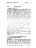
• Synchronous (Figure 2.1)
• Induction (Figure 2.2)
• Parametric, with magnetic anisotropy and permanent magnets (Figure 2.3)
Parametric generators have in most configurations doubly salient magnetic circuit structures, so they
may be called also doubly salient electric generators.
© 2006 by Taylor & Francis Group, LLC
2-2 Synchronous Generators
FIGURE 2.1 Synchronous generators.
FIGURE 2.2 Induction generators.
FIGURE 2.3 Parametric generators.
Synchronous generators
With heteropolar excitation With homopolar excitation
With variable reluctance rotor
Electrical With PMs
PM rotor
Claw pole electrical
excited rotor
Nonsalient
pole rotor
Salient pole
rotor
Variable
reluctance rotor
Variable reluctance
rotor with PM assistance
Variable reluctance rotor with
PMs and electrical excitation
Superconducting
rotor
Multipolar electrically (d.c.)
excited rotor
Induction generators
With cage rotor
With single stator
winding
With dual (main 2p
1
and
auxiliary 2p
2
) stator winding
With wound rotor (doubly fed)
induction generator WRIG
Parametric generators
Switched reluctance
generators (SRG)
Transverse flux
generators (TFG)
Flux reversal PM
generators (FRG)
Without PMs With rotor PMs
With stator PMs With single stator With PMs on stator With PMs on mover
With dual stator
Linear PM generators
© 2006 by Taylor & Francis Group, LLC
Principles of Electric Generators 2-3
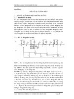
Synchronous generators [1–4] generally have a stator magnetic circuit made of laminations provided
with uniform slots that house a three-phase (sometimes a single or a two-phase) winding and a rotor.
It is the rotor design that leads to a cluster of synchronous generator configurations as seen in Figure 2.1.
They are all characterized by the rigid relationship between speed
n, frequency f
1
, and the number of
poles 2
p
1
:
(2.1)
Those that are direct current (DC) excited require a power electronics excitation control, while those
with permanent magnets (PMs) or variable reluctance rotors have to use full-power electronics in the
stator to operate at adjustable speeds. Finally, even electrically excited, synchronous generators may be
provided with full-power electronics in the stator when they work alone or in power grids with DC
high-
voltage cable transmission lines.
Each of these configurations will be presented, in terms of its principles, later in this chapter.
For powers in the MW/unit range and less, induction generators (IGs) were also introduced. They are
as follows (Figure 2.2):
• With cage rotor and single stator-winding
• With cage rotor and dual (main and additional) stator-winding with different number of poles
• With wound rotor
Pulse-width modulator (PWM) converters are connected to the stator (for the single stator-winding
and, respectively, to the auxiliary stator-winding in the case of dual stator-winding).
The principle of the IG with single stator-winding relies on the following equation:
(2.2)
where
f
1
> 0 = stator frequency
f
2
<>0 = slip (rotor) frequency
n = rotor speed (rps)
The term
f
2
may be either positive or negative in Equation 2.2, even zero, provided the PWM converter
in the wound rotor is capable of supporting a bidirectional power flow for speeds
n above f
1
/p
1
and
below
f
1
/p
1
.
Notice that for
f
2
= 0 (DC rotor excitation), the synchronous generator operation mode is reobtained
with the doubly fed IG.
The slip
S definition is as follows:
(2.3)
The slip is zero, as
f
2
= 0 (DC) for the synchronous generator mode.
For the dual stator-winding, the frequency–speed relationship is applied twice:
(2.4)
So, the rotor bars experience, in principle, currents of two distinct (rather low) frequencies
f
2
and f
2
′. In
general,
p
2
> p
1
to cover lower speeds.
n
f
p
=
1
fpnf
11 2
=+
S
f
f
=<>
2
1
0
fpnfpp
fpnf
11 221
12 2
=+ >
′
=+
′
;
© 2006 by Taylor & Francis Group, LLC
2-4 Synchronous Generators
The PWM converter feeds the auxiliary winding. Consequently, its rating is notably lower than that
of the full power of the main winding, and it is proportional to the speed variation range.
As it may also work in the pure synchronous mode, the doubly fed IG may be used up to the highest
levels of power for synchronous generators (400 MW units have been in use for some years in Japan)
and a 2
× 300 MW pump storage plant is now commissioned in Germany.
On the contrary, the cage-rotor IG is more suitable for powers in the MW and lower power range.
Parametric generators rely on the variable reluctance principle, but may also use PMs to enhance the
power and volume and to reduce generator losses.
There are quite a few configurations that suit this category, such as the switched reluctance generator
(SRG), the transverse flux PM generator (TFG), and the flux reversal generator (FRG). In general, the
principle on which they are based relies on coenergy variation due to magnetic anisotropy (with or
without PMs on the rotor or on the stator), in the absence of a pure traveling field with constant speed
(
f
1
/p), so characteristic for synchronous and IGs (machines).
2.2 Synchronous Generators
Synchronous generators (classifications are presented in Figure 2.1) are characterized by an uniformly
slotted stator laminated core that hosts a three-, two-, or one-phase alternating current (AC) winding
and a DC current excited, or PM-excited or variable saliency, rotor [1–5].
As only two traveling fields — of the stator and rotor — at relative standstill interact to produce a
rippleless torque, the speed
n is rigidly tied to stator frequency f
1
, because the rotor-produced magnetic
field is DC, typically heteropolar in synchronous generators.
They are built with nonsalient pole, distributed-excitation rotors (Figure 2.4) for 2
p
1
= 2,4 (that is,
high speed or turbogenerators) or with salient-pole concentrated-excitation rotors (Figure 2.5) for 2
p
1
> 4 (in general, for low-speed or hydrogenerators).
As power increases, the rotor peripheral speed also increases. In large turbogenerators, it may reach
more than 150 m/sec (in a 200 MVA machine
D
r
= 1.2 m diameter rotor at n = 3600 rpm, 2p
1
= 2, U =
πD
r
n = π × 1.2 × 3600/60 > 216 m/sec). The DC excitation placement in slots, with DC coil end
connections protected against centrifugal forces by rings of highly resilient resin materials, thus becomes
necessary. Also, the DC rotor current airgap field distribution is closer to a sinusoid. Consequently, the
FIGURE 2.4 Synchronous generator with nonsalient pole heteropolar DC distributed excitation.
Stator open uniform
slotting with 3 phase
winding (in general)
Rotor damper
cage bars
Rotor DC excitation coils
Shaft
Stator laminated
core
Airgap
2p
1
= 2 poles
Ldm = Lqm
Mild steel rotor
core
Slot wedge
(nonmagnetic or
magnetic)
q
d
© 2006 by Taylor & Francis Group, LLC
Principles of Electric Generators 2-5
harmonics content of the stator-motion-induced voltage (electromagnetic force or no load voltage) is
smaller, thus complying with the strict rules (standards) of large commercial power grids.
The rotor body is made of solid iron for better mechanical rigidity and heat transmission.
The stator slots in large synchronous generators are open (Figure 2.4 and Figure 2.5), and they are
provided, sometimes, with magnetic wedges to further reduce the field space harmonics and thus reduce
the electromagnetic force harmonics content and additional losses in the rotor damper cage. When
n =
f
1
/p
1
and for steady state (sinusoidal symmetric stator currents of constant amplitude), the rotor damper
cage currents are zero. However, should any load or mechanical transient occur, eddy currents show up
in the damper cage to attenuate the rotor oscillations when the stator is connected to a constant frequency
and voltage (high-power) grid.
The rationale neglects the stator magnetomotive force space harmonics due to the placement of
windings in slots and due to slot openings. These space harmonics induce voltages and thus produce
eddy currents in the rotor damper cage, even during steady state.
Also, even during steady state, if the stator phase currents are not symmetric, their inverse components
produce currents of 2
f
1
frequency in the damper cage. Consequently, to limit the rotor temperature, the
degree of current (load) unbalance permitted is limited by standards. Nonsalient pole DC excited rotor
synchronous generators are manufactured for 2
p
1
= 2, 4 poles high-speed turbogenerators that are driven
by gas or steam turbines.
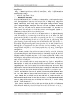
For lower-speed synchronous generators with a large number of poles (2
p
1
> 4), the rotors are made
of salient rotor poles provided with concentrated DC excitation coils. The peripheral speeds are lower
than those for turbogenerators, even for high-power hydrogenerators (for 200 MW 14 m rotor diameter
at 75 rpm, and 2
p
1
= 80, f
1
= 50 Hz, the peripheral speed U = π × D
r
× n = π × 14 × 75/60 > 50 m/sec).
About 80 m/sec is the limit, in general, for salient pole rotors. Still, the excitation coils have to be protected
against centrifugal forces.
The rotor pole shoes may be made of laminations, in order to reduce additional rotor losses, but the
rotor pole bodies and core are made of mild magnetic solid steel.
With a large number of poles, the stator windings are built for a smaller number of slot/pole couplings:
between 6 and 12, in many cases. The number of slots per pole and phase,
q, is thus between two and
four. The smaller the value of
q, the larger the space harmonics present in the electromagnetic force. A
fractionary
q might be preferred, say 2.5, which also avoids the subharmonics and leads to a cleaner
(more sinusoidal) electromagnetic force, to comply with the current standards.
The rotor pole shoes are provided with slots that house copper bars short-circuited by copper rings
to form a rather complete squirrel cage. A stronger damper cage was thus obtained.
FIGURE 2.5 Synchronous generator with salient pole heteropolar DC concentrated excitation.
ree phase AC windings
in slots
Rotor damper cage
Rotor pole shoe
Concentrated
DC coil for excitation
q
d
Shaft
Rotor
(Wheel and core)
2p
1
= 8 poles
Ldm > Lqm
© 2006 by Taylor & Francis Group, LLC
2-6 Synchronous Generators
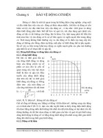
DC excitation power on the rotor is transmitted by either:
• Copper slip-rings and brushes (Figure 2.6)
• Brushless excitation systems (Figure 2.7)
The controlled rectifier, with power around 3% of generator rated power, and with a sizable voltage
reserve to force the current into the rotor quickly, controls the DC excitation currents according to the
needs of generator voltage and frequency stability.
Alternatively, an inverted synchronous generator (with its three-phase AC windings and diode rectifier
placed on the rotor and the DC excitation in the stator) may play the role of a brushless exciter (Figure
2.7). The field current of the exciter is controlled through a low-power half-controlled rectifier. Unfor-
tunately, the electrical time constant of the exciter generator notably slows the response in the main
synchronous generator excitation current control. Still another brushless exciter could be built around
FIGURE 2.6 Slip-ring-brush power electronics rectifier DC excitation system.
FIGURE 2.7 Brushless exciter with “flying diode” rectifier for synchronous generators.
Copper
slip-rings
Power
electronics
controlled
rectifier
Insulation
rings
Stator-fixed brushes
3~
Rotor coils
© 2006 by Taylor & Francis Group, LLC
Principles of Electric Generators 2-7
a single-phase (or three-phase) rotating transformer working at a frequency above 300 Hz to cut its
volume considerably (Figure 2.8). An inverter is required to feed the transformer, primarily at variable
voltage but constant frequency. The response time in the generator’s excitation current control is short,
and the size of the rotating transformer is rather small. Also, the response in the excitation control does
not depend on speed and may be used from a standstill.
Claw-pole (Lundell) synchronous generators are now built mainly for use as car alternators. The
excitation winding power is reduced considerably for the multiple rotor construction (2
p
1
= 10, 12, 14)
to reduce external diameter and machine volume.
The claw-pole solid cast iron structure (Figure 2.9) is less costly to manufacture, while the single ring-
shape excitation coil produces a multipolar airgap field (though with a three-dimensional field path)
with reduced copper volume and DC power losses.
The stator holds a simplified three-phase single-layer winding with three slots per pole, in general.
Though slip-rings and brushes are used, the power transmitted through them is small (in the order of
60 to 200 W for car and truck alternators); thus, low-power electronics are used to control the output.
The total cost of the claw-pole generator for automobiles, including field current control and the diode
full-power rectifier, is low, and so is the specific volume.
However the total efficiency, including the diode rectifier and excitation losses, is low at 14 V DC
output: below 55%. To blame are the diode losses (at 14 V DC), the mechanical losses, and the eddy
currents induced in the claw poles by the space and time harmonics of the stator currents magnetomotive
force. Increasing the voltage to 42 V DC would reduce the diode losses in relative terms, while the building
of the claw poles from composite magnetic materials would notably reduce the claw-pole eddy current
losses. A notably higher efficiency would result, even if the excitation power might slightly increase, due
to the lower permeability (500
μ
0
) of today’s best composite magnetic materials. Also, higher power levels
might be obtained.
The concept of a claw-pole alternator may be extended to the MW range, provided the number of
poles is increased (at 50/60 Hz or more) in variable speed wind and microhydrogenerators with DC-
controlled output voltage of a local DC bus.
FIGURE 2.8 Rotating transformer with inverter in the rotor as brushless exciter.
PWM
Variable
voltage
constant
f inverter
3~
Stator frame
Shaft
SG field
winding
© 2006 by Taylor & Francis Group, LLC
2-8 Synchronous Generators
Though the claw-pole synchronous generator could be built with the excitation on the stator, to avoid
brushes, the configuration is bulky, and the arrival of high-energy PMs for rotor DC excitation has put
it apparently to rest.
2.3 Permanent Magnet Synchronous Generators
The rapid development of high-energy PMs with a rather linear demagnetization curve led to widespread
use of PM synchronous motors for variable speed drives [6–10]. As electric machines are reversible by
principle, the generator regime is available, and, for direct-driven wind generators in the hundreds of
kilowatt or MW
range, such solutions are being proposed. Super-high-speed gas-turbine-driven PM
synchronous generators in the 100 kW range at 60 to 80 krpm are also introduced. Finally, PM synchro-
nous generators are being considered as starter generators for the cars of the near future.
There are two main types of rotors for PM synchronous generators:
• With rotor surface PMs (Figure 2.10) — nonsalient pole rotor (SPM)
• With interior PMs (Figure 2.11a through Figure 2.11c) — salient pole rotor (IPM)
The configuration in Figure 2.10 shows a PM rotor made with parallelepipedic PM pieces such that
each pole is patched with quite a few of them, circumferentially and axially.
The PMs are held tight to the solid (or laminated) rotor iron core by special adhesives, and a highly
resilient resin coating is added for mechanical rigidity.
The stator contains a laminated core with uniform slots (in general) that house a three-phase winding
with distributed (standard) coils or with concentrated (fractionary) coils.
The rotor is practically isotropic from the magnetic point of view. There is some minor difference
between the
d and the q axis magnetic permeances, because the PM recoil permeability (μ
rec
= (1.04 –
1.07)
μ
0
at 20°C) increases somewhat with temperature for NeFeB and SmCo high-energy PMs.
So, the rotor may be considered as magnetically nonsalient (the magnetization inductances
L
dm
and
L
qm
are almost equal to each other).
To protect the PMs, mechanically, and to produce reluctance torque, the interior PM pole rotors were
introduced. Two typical configurations are shown in Figure 2.11a through Figure 2.11c.
Figure 2.11a shows a practical solution for two-pole interior PM (IPM) rotors. A practical 2
p
1
= 4,6,…
IPM rotor as shown in Figure 2.11b has an inverse saliency: L
dm
< L
qm
, as is typical with IPM machines.
FIGURE 2.9 The claw-pole synchronous generator.
Brushes
+
Shaft
S
S
S
S
N
N
N
N
Cast iron
rotor claw
pole structure
Laminated
stator structure
with slots & 3 phase
winding
Ring shape
excitation coil
Claw pole
structure
on rotor
−
© 2006 by Taylor & Francis Group, LLC
Principles of Electric Generators 2-9
Finally, a high-saliency rotor (L
dm
> L
qm
), obtained with multiple flux barriers and PMs acting along axis
q (rather than axis d), is presented in Figure 2.11c. It is a typical IPM machine but with large magnetic
saliency. In such a machine, the reluctance torque may be larger than the PM interactive torque. The PM
field first saturates the rotor flux bridges and then overcompensates the stator-produced field in axis q.
This way, the stator flux along the q axis decreases with current in axis q. For flux weakening, the I
d
current component is reduced. A wide constant power (flux weakening) speed range of more than 5:1
was obtained this way. Starters/generators on cars are a typical application for this rotor.
As the PM’s role is limited, lower-grade (lower B
r
) PMs, at lower costs, may be used.
It is also possible to use the variable reluctance rotor with high magnetic saliency (Figure 2.11a) without
permanent magnets. With the reluctance generator, either power grid or stand-alone mode operation is
feasible. For stand-alone operation, capacitor self-excitation is needed. The performance is moderate,
but the rotor cost is also moderate. Standby power sources would be a good application for reluctance
synchronous generators with high saliency L
dm
/L
qm
> 4.
PM synchronous generators are characterized by high torque (power) density and high efficiency
(excitation losses are zero). However, the costs of high-energy PMs are still up to $100 per kilogram.
Also, to control the output, full-power electronics are needed in the stator (Figure 2.12).
A bidirectional power flow pulse-width modulator (PWM) converter, with adequate filtering and control,
may run the PM machine either as a motor (for starting the gas turbine) or as a generator, with controlled
output at variable speed. The generator may work in the power-grid mode or in stand-alone mode. These
flexibility features, together with fast power-active and power-reactive decoupled control at variable speed,
may make such solutions a way of the future, at least in the tens and hundreds of kilowatts range.
Many other PM synchronous generator configurations were introduced, such as those with axial airgap.
Among them, we will mention one that is typical in the sense that it uses the IPM reluctance rotor (Figure
2.11c), but it adds an electrical excitation. (Figure 2.13) [11].
In addition to the reluctance and PM interaction torque, there will be an excitation interaction torque.
The excitation current may be positive or negative to add or subtract from I
d
current component in the
stator. This way, at low speeds, the controlled positive field current will increase and control the output
voltage, while at high speeds, a negative field current will suppress the electromagnetic torque, when
needed, to keep the voltage constant.
For DC-controlled output only a diode rectifier is necessary, as the output voltage is regulated via
DC current control in four quadrants. A low-power four-quadrant chopper is needed. For wide speed
FIGURE 2.10 Surface PM rotor (2p
1
= four poles).
q
d
Shaft
Resin coating
PM cubicles
Solid
(or laminated)
rotor iron core
© 2006 by Taylor & Francis Group, LLC
2-10 Synchronous Generators
FIGURE 2.11 Interior PM rotors: (a) 2p
1
= 2 poles, (b) 2p
1
= 4, and (c) with rotor flux barriers (IPM – reluctance).
q
d
L
dm
= L
qm
Laminated rotor
PMs
S
S
S
S
N
N
N
N
2p
1
= 2 poles
q
d
L
dm
< L
qm
Laminated
rotor
(a)
(b)
(c)
PMs
S
S
S
S
N
N
N
N
2p
1
= 4 poles
L
dm
>> L
qm
2p
1
= 4
S
S
S
N
N
N
q
d
PMs
Laminate
rotor core
Flux barriers
Flux bridges
© 2006 by Taylor & Francis Group, LLC
Principles of Electric Generators 2-11
range applications such a hybrid excitation rotor may be a competitive solution. The rotor is not very
rugged mechanically, but it can easily handle peripheral speeds of up to 50 m/sec (10,000 rpm for 0.1 m
diameter rotor).
2.4 The Homopolar Synchronous Generator
Placing both the DC excitation coils and the three-phase AC winding on the stator characterizes the so-
called homopolar (or inductor) synchronous machine (generator and motor; see Figure 2.14a through
Figure 2.14c).
The rather rugged rotor with solid (even laminated) salient poles and solid core is an added advantage.
The salient rotor poles (segments) and interpoles produce a salient magnetic structure with a notable
saliency ratio, especially if the airgap is small.
Consequently, the magnetic field produced by the DC field current closes paths, partially axially and
partially circumferentially, through stator and rotor, but it is tied (fixed) to the rotor pole axis.
It is always maximum in the axis of rotor poles and small, but of the same polarity, in the axis of
interpoles. An AC airgap magnetic component is present in this homopolar distribution. Its peak value
is ideally 50% of maximum airgap field of the DC excitation current. Fringing reduces it 35 to 40%
(Figure 2.14a through Figure 2.14c), at best.
The machine is a salient pole machine with doubled airgap, but it behaves as a nonsalient pole rotor
one and with rotor excitation.
So, for the same airgap flux density fundamental B
g1
(Figure 2.14a through Figure 2.14c), the same
mechanical airgap, the DC magnetomotive force of the field winding is doubled, and the power loss
quadruples. However, the ring-shaped coil reduces the copper weight and losses (especially when the
FIGURE 2.12 Bidirectional full-power electronics control.
FIGURE 2.13 Biaxial excitation PM reluctance rotor generator (biaxial excitation generator for automobiles
[BEGA]).
PM generator
Variable
speed
Gas
turbine
N
S
3~
Bidirectional power
converter
Lamination
d
d
q
q
PM
Wedge
Coil
© 2006 by Taylor & Francis Group, LLC
2-12 Synchronous Generators
FIGURE 2.14 The homopolar synchronous generator: (a) and (b) the geometry and (c) airgap excitation field
distribution.
© 2006 by Taylor & Francis Group, LLC
Principles of Electric Generators 2-13
number of poles increases) in comparison with a multipolar heteropolar DC rotor excitation system.
The blessing of circularity comes into place here. We also have to note the additional end connection in
the middle of the stator AC three-phase winding, between the two slotted laminated cores.
The rotor mechanical ruggedness is superior only with solid iron poles when made in one piece.
Unfortunately, stator magnetomotive force and slot space harmonics induce eddy currents in the rotor
solid poles, notably reducing the efficiency, typically below 90% in a 15 kW, 15,000 rpm machine.
2.5 Induction Generator
The cage-rotor induction machine is known to work as a generator, provided the following:
• The frequency f
1
is smaller than n × p
1
(speed × pole pairs): S < 0 (Figure 2.15a).
• There is a source to magnetize the machine.
An induction machine working as a motor, supplied to fixed frequency and voltage f
1
, V
1
power grid
becomes a generator if it is driven by a prime mover above no load ideal speed f
1
/p
1
:
(2.5)
Alternatively, the induction machine with the cage rotor may self-excite on a capacitor at its terminals
(Figure 2.15b).
For an IG connected to a strong (constant frequency and voltage) power grid, when the speed n
increases (above f
1
/p
1
), the active power delivered to the power grid increases, but so does the reactive
power drawn from the power grid.
Many existing wind generators use such cage-rotor IGs connected to the power grid. The control is
only mechanical. The blade pitch angle is adjusted according to wind speed and power delivery require-
ments. However, such IGs tend to be rigid, as they are stable only until n reaches the following value:
FIGURE 2.15 Cage-rotor induction generator: (a) at power grid: V
1
= ct, f
1
= ct, and (b) stand-alone (capacitor
excited): V
1
, f
1
, variable with speed and load.
Power grid
3~
f
1
= ct
V
1
= ct
Reactive power flow
Active power flow
n
n > f
1
/p
1
Prime
mover
V
1
f
1
(variable
with speed
and load)
(a)
(b)
ree
phase
load
Mag curve
ω
1
× ψ
1
≅ V
10
ω
1
C
λ
I
10
V
cap
=
n > f
1
/p
1
Reactive power flow
Active power flow
n
C
Δ
Prime
mover
n
f
p
>
1
1
© 2006 by Taylor & Francis Group, LLC
2-14 Synchronous Generators
(2.6)
where S
K
is the critical sleep, which decreases with power and is, anyway, below 0.08 for IGs in the
hundreds of kilowatts. Additional parallel capacitors at the power grid are required to compensate for
the reactive power drained by the IG.
Alternatively, the reactive power may be provided by parallel (plus series) capacitors (Figure 2.15b).
In this case, we have a self-excitation process that requires some remanent flux in the rotor (from previous
operation) and the presence of magnetic saturation (Figure 2.15b). The frequency f
1
of self-excitation
voltage (under no load) depends on the capacitor value and on the magnetization curve of the induction
machine Ψ
1
(I
10
):
(2.7)
The trouble is that on load, even if the speed is constant through prime mover speed control, the
output voltage and frequency vary with load. For constant speed, if frequency reduction under a load of
1 Hz is acceptable, voltage control suffices. A three-phase AC chopper (Variac™) supplying the capacitors
would do it, but the harmonics introduced by it have to be filtered out. In simple applications, a
combination of parallel and series capacitors would provide constant (with 3 to 5% regulation) voltage
up to rated load.
Now, if variable speed is to be used, then, for constant voltage and frequency, PWM converters are
needed. Such configurations are illustrated in Figure 2.16a and Figure 2.16b. A bidirectional power flow
PWM converter (Figure 2.16a) provides both generating and motoring functions at variable speed. The
capacitor in the DC line of the converter may lead not only to active, but also to reactive, power delivery.
Connection to the power grid without large transients is implicit, and so is fast, decoupled, active, and
reactive power control.
The stand-alone configuration in Figure 2.16b is less expensive, but it provides only unidirectional
power flow. A typical V
1
/f
1
converter for drives is used. It is possible to inverse the connections, that is,
to connect the diode rectifier and capacitors to the grid and the converter to the machine. This way, the
system works as a variable speed drive for pumping and so forth, if a local power grid is available. This
commutation may be done automatically, but it would take 1 to 2 min. For variable speed, in a limited
range, an excitation capacitor in two stages would provide the diode rectifier with only slightly variable
DC link voltage. Provided the minimum and maximum converter voltage limits are met, the former
would operate over the entire speed range. Now, the converter is V
1
/f
1
controlled for constant voltage
and frequency.
A transformer (Y, Y
0
) may be needed to accommodate unbalanced (or single-phase) loads.
The output voltage may be close-loop controlled through the PWM converter. On the other end, the
bidirectional PWM converter configuration may be provided with a reconfigurable control system so as
to work not only on the power grid, but also to separate itself smoothly to operate as a stand-alone or
to wait on standby and then be reconnected smoothly to the power grid. Thus, multifunctional power
generation at variable speed is produced. As evident in Figure 2.16a and Figure 2.16b, full-power elec-
tronics are required. For a limited speed range, say up to 25%, it is possible to use two IGs with cage-
rotor and different pole numbers (2p
2
/2p
1
= 8/6, 5/4, 4/3 ). The one with more poles (2p
2
> 2p
1
) is rated
at 25% of rated power and is fed from a bidirectional power converter sized also at about 25%. The
scheme works at the power grid (Figure 2.17).
The soft-starter reduces the synchronization transients and disconnects the 100% IG when the power
required is below 25%. Then, the 25% IG remains alone at work, at variable speed (n < f
1
/p
1
), to tap the
energy available from (for example) low-speed wind or from a low-head microhydroturbine. Also, above
25% load, when the main (100%) IG works, the 25% IG may add power as generator or work in motoring
n
f
p
S
Kmax
=+
()
1
1
1
VI fVI
Cf
C
Y
10 1 10 1 10
1
2
3
2
≈⋅⋅⋅≈=
⋅⋅⋅
ψπ
π
()
Δ
© 2006 by Taylor & Francis Group, LLC
Principles of Electric Generators 2-15
for better dynamics and stability. Now, we may imagine a single rotor-stator IG with two separate stator
windings (2p
2
> 2p
1
) to perform the same task.
The reduction in rating, from 100% to 25%, of the bidirectional PWM converter is noteworthy.
The main advantage of the dual IG or dual-stator winding IG is lower cost, although the cost is for
lower performance (low-speed range above f
1
/p
1
).
2.6 The Wound Rotor (Doubly Fed) Induction Generator (WRIG)
It all started between 1907 and 1913, with the Scherbius and Kraemer cascade configurations, which are
both slip-power recovery schemes of wound-rotor induction machines. Leonhard analyzed it pertinently
FIGURE 2.16 Cage-rotor induction generators for variable speed: (a) at power grid V
1
= ct., f
1
= ct., and (b) stand-
alone V
1
″
= ct., f
1
″
= ct. (controlled).
FIGURE 2.17 Dual-induction generator system for limited speed variation range.
Prime mover
n-Variable speed
Power
grid
Bidirectional
PWM
converter
To load
Trans-
former
Y/Y0
Prime mover
V/f
controller
−V
f′′
1
v′′
1
Typical V/f drive
PWM
Voltage
source
converter
(a)
(b)
25%
100%
100%
Power
grid
Soft
starter
Bidirectional power
converter (25%)
© 2006 by Taylor & Francis Group, LLC
2-16 Synchronous Generators
in 1928, but adequate power electronics for it were not available by then. A slip recovery scheme with
thyristor power electronics is shown in Figure 2.18a. Unidirectional power flow, from IG rotor to the
converter, is only feasible because of the diode rectifier. A step-up transformer is necessary for voltage
adaption, while the thyristor inverter produces constant voltage and frequency output. The principle of
operation is based on the frequency theorem of traveling fields.
, and variable f
1
= ct (2.8)
Negative frequency means that the sequence of rotor phases is different from the sequence of stator
phases. Now if f
2
is variable, n may also be variable, as long as Equation 2.8 is fulfilled.
That is, constant frequency f
1
is provided in the stator for adjustable speed. The system may work at
the power grid or even as a stand-alone, although with reconfigurable control. When f
2
> 0, n < f
1
/p
1
, we
have subsynchronous operation. The case for f
2
< 0, n > f
1
/p
1
corresponds to hypersynchronous operation.
Synchronous operation takes place at f
2
= 0, which is not feasible with the diode rectifier current source
inverter, but it is feasible with the bidirectional PWM converter.
The slip recovery system can work as a subsynchronous (n < f
1
/p) motor or as a supersynchronous (n
> f
1
/p) generator. The WRIG with bidirectional PWM converter may work as a motor and generator for
both subsynchronous and supersynchronous speed. The power flow directions for such a system are
shown in Figure 2.19a and Figure 2.19b.
The converter rating is commensurable to speed range, that is, to maximum slip S
max
:
FIGURE 2.18 Wound rotor induction generator (WRIG): (a) with diode rectifier (slip recovery system), and (b)
with bidirectional pulse-width modulator (PWM) converter.
WRIG
Prime
mover
yristor
inverter
(a)
(b)
Power flow
Step-up
transformer
3~
Power grid
Bidirectional PWM converter
fnpff
1122
0=+ <>;
© 2006 by Taylor & Francis Group, LLC
Principles of Electric Generators 2-17
(2.9)
K = 1–1.4 depending on the reactive power requirements from the converter
Notice that, being placed in the rotor circuit, through slip-rings and brushes, the converter rating is
around |S
max
| in percent. The larger the speed range, the larger the rating and the costs of the converter.
Also, the fully bidirectional PWM converter — as a back-to-back voltage source multilevel PWM con-
verter system — may provide fast and continuous decoupled active and reactive power control operation,
even at synchronism (f
2
= 0, DC rotor excitation). And, it may perform the self-starting as well. The self-
starting is done by short-circuiting the stator, previously disconnected from the power grid, and supplying
the rotor through the PWM converter in the subsynchronous motoring mode. The rotor accelerates up
to a prescribed speed corresponding to f
2
> f
1
(1 – S
max
). Then, the stator winding is opened and, with
the rotor freewheeling, the stator no load voltage, sequence and frequency are adjusted to coincide with
that of the power grid, by adequate PWM converter control. Finally, the stator winding is connected to
the power grid without notable transients.
This kind of rotor-starting procedure requires f
2
≈ (0.8 – 1)f
1
, which means that the standard cyclo-
converter is out of the question. So, it is only the back-to-back voltage PWM multilevel converter or the
matrix converter that is suitable for full exploitation of motoring/generating at sub- and supersynchro-
nous speeds, so typical in pump storage applications.
2.7 Parametric Generators
Parametric generators exploit the magnetic anisotropy of both stator and rotor. PMs may be added on
the stator or on the rotor. Single magnetic saliency with PMs on the rotor is also used in some configu-
rations. Parametric generators use nonoverlapping (concentrated) windings to reduce end-connection
FIGURE 2.19 Operation modes of wound rotor induction generator (WRIG) with bidirectional pulse-width mod-
ulator (PWM) converter (in the rotor): (a) S < 0 and (b) S > 0.
P
el
rotor
P
el
stator
P
loss
P
mec
Motor
P
el
rotor
P
el
stator
P
loss
P
mec
Generator
P
el
rotor
P
el
stator
P
loss
P
mec
Motor
(a)
(b)
P
el
rotor
P
el
stator
P
loss
P
mec
Generator
KVA K
f
f
rating
=×⎡
⎣
⎤
⎦
2
1
100
max
%
© 2006 by Taylor & Francis Group, LLC
2-18 Synchronous Generators
copper losses on the stator. As the stator magnetomotive force does not produce a pure traveling field,
there are core losses both in the stator and in the rotor. The simplicity and ruggedness of such generators
make them adequate for use in some applications.
Among parametric generators, some of the most representative are detailed here:
• The switched reluctance generators (SRGs):
• Without PMs
• With PMs on the stator or on the rotor
• The transverse flux generators (TFGs):
• With rotor PMs
• With stator PMs
• The flux reversal generators (FRGs):
• With PMs on the stator
• With PMs on the rotor (and flux concentration)
• The linear motion alternators (LMAs):
• With coil mover and PMs on the stator
• With PM mover, tubular or flat (with PM flux concentration)
• With iron mover and PMs on the stator
The SRG [12] has a double saliency magnetic laminated structure — on the stator and rotor — and
concentrated coils on the stator (Figure 2.20a and Figure 2.20b). The stator phases are PWM voltage fed
as long as the rotor poles are approaching them, one at a time, for the three-phase configuration. The
phase inductances vary with rotor position (Figure 2.21a and Figure 2.21b) and, at least for the three-
phase configuration, there is little magnetic coupling between phases.
Eventually, each phase is turned on around point A (in Figure 2.21a and Figure 2.21b); then it
magnetizes the phase, and the dL/dθ effect produces a motion-induced voltage (electromagnetic force)
which, in interaction with the phase current, produces torque. The phase is turned off around point B,
when the next phase is turned on. The current polarity is not relevant; thus, positive current is flowed
through voltage PWM. The maximum voltage is applied until the phase current magnetizes to maximum
admitted current.
FIGURE 2.20 Switched reluctance generators (SRGs): (a) single-phase: 4/4 (4 × 4 poles) and (b) three-phase: 6/4
(6 × 4 poles).
A
Aʹ
Aʹ
Aʹ
Aʹ
Aʹ
A
A
A
A
A
A
A
Single-phase
winding
(a)
(b)
Laminated
stator core
Aʹ
Aʹ
Aʹ
Aʹ
Aʹ
A
A
A
Aʹ
A
ree-phase
winding
Laminated
stator core
Aʹ
Bʹ
Bʹ
Bʹ
B
B
B
B
Bʹ
Cʹ
C
ʹ
CC
C
C
Cʹ
Cʹ
© 2006 by Taylor & Francis Group, LLC
Principles of Electric Generators 2-19
As part of the AB interval available for generating is lost to the magnetization process, the latter takes
up around 30% of energy available per cycle. For the single-phase machine, the torque, as expected, has
notches, as only the negative slopes of the inductance are adequate for generating.
It is machine simplicity and ruggedness that characterize SRGs. High speed is feasible. Rotor higher
temperature due to the local environment is also acceptable, because there are no PMs or windings on
the rotor. PMs may be added on the rotor (Figure 2.22a and Figure 2.22b) [13,14]. In this situation, the
current polarity has to change, and the torque production relies heavily on phase interaction through
PMs. The reluctance torque is small.
Alternatively, PMs may be placed on the stator (Figure 2.22c) [15] with some PM flux concentration.
Again, the reluctance torque is reduced, and PM torque prevails. The PM flux polarity in one phase does
not change sign, so we may call it a homopolar PM excitation.
Other SRG configurations with homopolar excitation flux were proposed but did not reach very far
in the markets.
2.7.1 The Flux Reversal Generators
In these configurations, reliance is on PM flux switch (reversal) in the stator-concentrated coils (Figure
2.23a [16]). The PM flux linkage in the stator coils of Figure 2.23a changes sign when the rotor moves
FIGURE 2.21 Phase inductance vs. rotor position: (a) the single-phase 4/4 switched reluctance generator (SRG)
and (b) the three-phase 6/4 SRG.
AA
θ
r
B
B
L
ph
Motor MotorGenerator
π/4 π/2
(a)
(b)
3π/2 π
Generator
L
aa
A
AA A
AAA
A
Gen
Gen
Gen Gen
π/6 π/3 π/2 π
Gen
B
B
Gen B
BB
B
Gen B
Gen B B
θ
r
θ
r
θ
r
A
L
bb
L
cc
© 2006 by Taylor & Francis Group, LLC
2-20 Synchronous Generators
FIGURE 2.22 Permanent magnet (PM)-assisted switched reluctance generators (SRGs): (a) with long PMs on the
rotor, (b) with short PMs on the rotor, and (c) with PMs on the stator.
FIGURE 2.23 Flux reversal generators (FRGs) with stator permanent magnets (PMs): (a) the single-phase 4/2
flux–switch alternator and (b) the three-phase 6/8 FRG.
S
N
S
N
A
C
C
B
B
S
(a) (b)
S
S
S
S
S
N
N
N
N
N
N
N
N
N
N
S
S
N
N
S
S
S
S
Aʹ
AAʹ
Cʹ
Cʹ
Bʹ
Bʹ
© 2006 by Taylor & Francis Group, LLC
Principles of Electric Generators 2-21
90° (mechanical) and does the same, for each phase in Figure 2.23b for the three-phase FRG, when the
rotor moves 22.5° mechanical degrees.
In general, it is π/N
r
(which corresponds to electrical radius). The electrical and mechanical radians
are related as follows:
(2.10)
So, the frequency of the electromagnetic force f
1
is as if the number of pole pairs on the rotor was N
r
.
The three-phase FRG configuration [17] makes better use of the stator and rotor core, and the
manufacturing process is easier than that for the single-phase configuration, as the coils are inserted by
conventional technology. Premade stator poles, with coils on, may be mounted inside the stator back
iron, as done with rotor poles in salient poles in hydrogenerators. The main problem is the large flux
fringing due to the juxtaposition of the North and South Poles (there could be 2,4,6,… of them on a
stator pole). This reduces the useful flux to about 0.3 to 0.4 of its ideal value (in homopolar stator
excitation, this is normal). PM flux concentration should provide better torque density for the same
power factor. A three-phase configuration as described is shown on Figure 2.24.
It is evident that the manufacturing of a stator is a bit more complicated, and usage of the stator core
is partial but still, PM flux concentration may increase the torque density without compromising the power
factor too much. The phases are magnetically independent, and thus, high fault tolerance is expected.
For a better core utilization, the PMs with flux concentration may be placed on the rotor. An interior
stator is added to complete the magnetic circuit (Figure 2.25).
The second (interior) windingless stator poses some manufacturing problems (the rotor also), but the
higher torque/volume at an acceptable power factor may justify it. The power factor is mentioned here
because it influences the converter kilo volt amps (KVAs) through reactive power demands.
FRGs are, in general, meant for mainly very low-speed applications, such as direct-driven wind
generators on vessel generator/motors, and so forth.
2.7.2 The Transverse Flux Generators (TFGs)
TFGs are built in single-phase configurations with ring-shaped stator coils and surface PMs on the rotor
(Figure 2.26) or with PM rotor flux concentration (Figure 2.27) [17,18].
The double-sided (dual-stator) configuration in Figure 2.27 takes advantage of PM flux concentration
on the rotor. In general, TFGs are characterized by moderately low winding losses, due to the blessing
of the ring-shaped coil.
FIGURE 2.24 Three-phase flux reversal generator (FRG) with stator permanent magnet (PM) flux concentration.
Air
Rotor
Winding
Permanent
magnet
αα
el r mec r
NfNn==⋅,
1
© 2006 by Taylor & Francis Group, LLC
2-22 Synchronous Generators
FIGURE 2.25 Flux reversal generator (FRG) with rotor permanent magnet (PM) flux concentration.
FIGURE 2.26 Double-sided transverse flux generator (TFG) with surface PM rotor.
SSNN
SS
SS
SS
SS
SS
SS
SS
SS
SS
SS
SS
SS
SS
SS
SS
SS
SS
SS
SS
SS
SS
NN
NN
NN
NN
NN
NN
NN
NN
N
N
NN
NN
NN
N
N
NN
NN
NN
NN
NN
N
N
NN
NN
NN
SS
PM
Shaft
Stator II
Stator I
Winding
© 2006 by Taylor & Francis Group, LLC
Principles of Electric Generators 2-23
A three-phase machine is built by adding axially three single-phase units, properly displaced tangen-
tially by 2/3 of a pole with each other. It is evident that the stators could best be built from magnetic
composite materials. However, this solution would reduce torque density, because the permeability of
such materials is below 500 μ
0
under some magnetic saturation. The core losses would be reduced if
frequency goes above 600 Hz with magnetic composite materials (magnetic powder).
The stator-PM TFG (originally called the axial flux circumferential current PM machine [AFCC] [19])
imposes the use of composite magnetic materials both on the stator and on the rotor due to its intricated
geometry. Again, it is essentially a single-phase machine. PM flux concentration occurs along the axial
direction. Good usage of PMs and cores is inherent in the axial-airgap stator PM FRG shown in Figure
2.28a and Figure 2.28b.
FRGs need more PMs than usual, but the torque density is rather good, and compact geometries are
very likely. The large number of poles on the rotor in most TFGs leads to a good frequency, unless speed
is not very low.
The rather high torque density (in Nm/m
3
, or [6 to 9] N/cm
2
of rotor shear stress) is inherent, as the
number of PM flux reversals (poles) in the stator ring-shaped coils is large per one revolution. This effect
may be called torque magnification [11].
2.7.3 Linear Motion Alternators
The microphone is the classical example of a linear motion alternator (LMA) with moving coil. The
loudspeaker illustrates its motoring operation mode.
Though there are many potential LMA configurations (or actuators), they all use PMs and fall into
three main categories [20]:
• With moving coil (and stator PMs) — Figure 2.29a
• With moving PMs (and stator coil) — Figure 2.29b
• With moving iron (and stator PMs) — Figure 2.29c
FIGURE 2.27 Double-sided transverse flux generator (TFG) with rotor PM flux concentration.
© 2006 by Taylor & Francis Group, LLC
2-24 Synchronous Generators
In essence, the PM flux linkage in the coil changes sign when the mover travels the excursion length l
stroke
which serves as a kind of pole pitch. So they are, in a way, single-phase flux reversal machines. The
average speed U
av
is as follows:
(2.11)
where f
1
= the frequency of mechanical oscillations.
To secure high efficiency, beryllium-copper flexured springs (Figure 2.30) are used to store the kinetic
energy of the mover at excursion ends. They also serve as linear bearings. The proper frequency of these
mechanical springs f
m
should be equal to electrical frequency:
(2.12)
where
K = spring rigidity coefficient
m = moving mass
The current is in phase with speed for best operation.
The strokes involved in LMAs are in the order of 0.5 to 100 mm or so. Their power, in general, is
limited to 10 to 50 kW at 50 (60) Hz.
They are basically synchronous single-phase machines with harmonic motion and linear flux to
position ideal variation.
Further increasing the power and volume requires — if average speed U
s
is limited — configurations
with PM flux concentration and three phases. Such a single-phase flat configuration, with moving PMs,
is shown in Figure 2.31 [26].
Again, it is a single-phase device, and the PM flux reverses polarity when the mover advances one
“small,” stator, pole (tooth). The two twin stators are displaced by one stator tooth also, to provide for
optimal magnetic circuit completion. Large airgap PM flux densities of up to 1.25 T may be obtained
under the stator teeth with 0.65 T left for armature reaction, to secure both high-force (power) density
and a satisfactory power factor (or reasonable IX/E = 0.5 ratio; X = machine reactance). The PM height
FIGURE 2.28 TFG with stator — permanent magnet (PM) flux concentration: (a) with axial airgap and (b) with
radial airgap.
Stator pole
Magnet
Winding
S
S
N
N
Rotor
Stator pole
(a)
(b)
Magnet
Winding
Rotor pole
Magnet
Ulf
av stroke
=⋅ ⋅2
1
ff
K
m
em
==
1
2π
© 2006 by Taylor & Francis Group, LLC
Principles of Electric Generators 2-25
FIGURE 2.29 Commercial linear motion alternators: (a) with moving coil, (b) with moving permanent magnets
(PMs), and (c) with moving iron.
FIGURE 2.30 (a) Tubular linear motion alternator (LMA) and (b) with plunger supported on flexural springs.
Φ
m
Φ
i
Displacement
x
rust, F
x
Exciting
Current I
Yok e
Permanent
magnet
S
N
Coil
Short ring
(a) (b)
(c)
Coil
bobbin
non-oriented
grain
steel
coil
multimagnet
plunger
NSS
SNN
l=2nl
s
, n=3
l
s
NSNSNS
NSNSNS
g
D
ls
N
c
-
D
es
x
x
turn coil
(all coils
connected
in series)
h
core
h
coil
a
2p=4poles
D
PO
h
m
b
p
N
N
S
S
α
p
(a)
(b)