the induction machine handbook chuong (3)
Bạn đang xem bản rút gọn của tài liệu. Xem và tải ngay bản đầy đủ của tài liệu tại đây (568.59 KB, 17 trang )
Author: Ion Boldea, S.A.Nasar………… ………
Chapter 3
MAGNETIC, ELECTRIC,
AND INSULATION MATERIALS FOR IM
3.1. INTRODUCTION
Induction machines contain magnetic circuits traveled by a.c. and traveling
magnetic fields and electric circuits flowed by alternative currents. The electric
circuits are insulated from the magnetic circuits (cores). The insulation system
comprises the conductor, slot and interphase insulation.
Magnetic, electrical, and insulation materials are characterized by their
characteristics (B(H) curve, electrical resistivity, dielectric constant, and
breakdown electric field (V/m)) and their losses.
At frequencies encountered in IMs (up to tens of kHz, when PWM inverter
fed), the insulation losses are neglected. Soft magnetic materials are used in IM
as the magnetic field is current produced. The flux density (B)/magnetic field
(H) curve and cycle depend on the soft material composition and fabrication
process. Their losses in W/kg depend on the B-H hysteresis cycle, frequency,
electrical resistivity, and the a.c. (or) traveling field penetration into the soft
magnetic material.
Silicon steel sheets are standard soft magnetic materials for IMs.
Amorphous soft powder materials have been introduced recently with some
potential for high frequency (high speed) IMs. The pure copper is the favorite
material for the stator electric circuit (windings), while aluminum or brass is
used for rotor squirrel cage windings.
Insulation materials are getting thinner and better and are ranked into a few
classes: A (105
0
C), B (130
0
C), F (155
0
C), H (180
0
C).
3.2. SOFT MAGNETIC MATERIALS
In free space the flux density B and the magnetic field H are related by the
permeability of free space µ
0
= 4π10
-7
H/m (S.I.)
⋅
µ=
m
A
H
m
H
m
Wb
B
0
2
(3.1)
Within a certain material a different magnetization process occurs.
R0
;HB µµ=µ⋅µ=
(3.2)
In (3.2) µ is termed as permeability and µ
R
relative permeability
(nondimensional).
Permeability is defined for homogenous (uniform quality) and isotropic
(same properties in all directions) materials. In nonhomogeneous or (and)
© 2002 by CRC Press LLC
Author: Ion Boldea, S.A.Nasar………… ………
nonisotropic materials, µ becomes a tensor. Most common materials are
nonlinear:
µ
varies with B.
A material is classified according to the value of its relative permeability,
µ
R
, which is related to its atomic structure.
Most nonmagnetic materials are either paramagnetic-with µ
R
slightly
greater than 1.0, or diamagnetic with µ
R
slightly less than 1.0. Superconductors
are perfect diamagnetic materials. In such materials when B
Æ
0, µ
R
Æ
0.
Magnetic properties are related to the existence of permanent magnetic
dipoles within the matter.
There are quite a few classes of more magnetic materials (µ
R
>> 1). Among,
them we will deal here with soft ferromagnetic materials. Soft magnetic
materials include alloys made of iron, nickel, cobalt and one rare earth element
and/or soft steels with silicon.
There is also a class of magnetic materials made of powdered iron particles
(or other magnetic material) suspended in an epoxy or plastic (nonferrous)
matrix. These softpowder magnetic materials are formed by compression or
injection, molding or other techniques.
There are a number of properties of interest in a soft magnetic material such
as permeability versus B, saturation flux density, H(B), temperature variation of
permeability, hysteresis characteristics, electric conductivity, Curie temperature,
and loss coefficients.
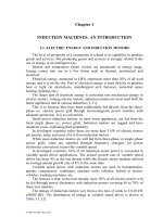
The graphical representation of nonlinear B(H) curve (besides the pertinent
table) is of high interest (Figure 3.1). Also of high interest is the hysteresis loop
(Figure 3.2).
B
H
I
α
α
II
III
B(t)
H(A/m)
n
d
Figure 3.1 Typical B-H curve
There are quite a few standard laboratory methods to obtain these two
characteristics. The B-H curve can be obtained two ways: the virgin (initial) B-
H curve, obtained from a totally demagnetized sample; the normal (average) B-
H curve, obtained as the tips of hysteresis loops of increasing magnitude. There
is only a small difference between the two methods.
© 2002 by CRC Press LLC
Author: Ion Boldea, S.A.Nasar………… ………
-20 -10 10
20
0.4
0.8
1.2
1.6
B(T)
H(A/m)
60Hz
400Hz
Figure 3.2 Deltamax tape-wound core 0.5 mm strip hysteresis loop
The B-H curve is the result of domain changes within the magnetic
material. The domains of soft magnetic materials are 10
-4
-10
-7
m in size. When
completely demagnetized, these domains have random magnetization with zero
flux in all finite samples.
When an external magnetic field H is applied, the domains aligned to H
tend to grow when increasing B (region I on Figure 3.1). In region II, H is
further increased and the domain walls move rapidly until each crystal of the
material becomes a single domain. In region III, the domains rotate towards
alignment with H. This results in magnetic saturation B
s
. Beyond this condition,
the small increase in B is basically due to the increase in the space occupied by
the material for B = µ
0
H
r0
.
This “free space” flux density may be subtracted to obtain the intrinsic
magnetization curve. The nonlinear character of B-H curve (Figure 3.1) leads to
two different definitions of relative permeability.
• The normal permeability µ
Rn
:
0
n
0
Rn
tan
H
B
µ
α
=
µ
=µ
(3.3)
• The differential relative permeability µ
Rd
:
0
dan
0
Rd
t
dH
dB
µ
α
=
µ
=µ
(3.4)
Only in region II, µ
Rn
= µ
Rd
. In region I and III, in general, µ
Rn
> µ
Rd
(Figure
3.3). The permeability is maximum in region II. For M19 silicon steel sheets (B
s
= 2T, H
s
= 40,000 A/m, µ
Rmax
= 10,000).
So the minimum relative permeability is
()
! 8.39
40000104
0.2
7
T0.2B
Rn
s
=
⋅π
=µ
−
=
(3.5)
© 2002 by CRC Press LLC
Author: Ion Boldea, S.A.Nasar………… ………
µ
µ
1
µ
H
Rn
Rd
R
Figure 3.3 Relative permeability versus H
The second graphical characteristic of interest is the hysteresis loop (Figure
3.2). This is a symmetrical hysteresis loop obtained after a number of reversals
of magnetic field (force) between ±H
c
. The area within the loop is related to the
energy required to reverse the magnetic domain walls as H is reversed. This
nonreversible energy is called hysteresis loss, and varies with temperature and
frequency of H reversals in a given material (Figure 3.2). A typical
magnetization curve B-H for silicon steel nonoriented grain is given in Table
3.1.
Table 3.1. B-H curve for silicon (3.5%) steel (0.5mm thick) at 50Hz
B(T)
0.05 0.1 0.15 0.2 0.25 0.3 0.35 0.4 0.45 0.5
H(A/m)
22.8 35 45 49 57 65 70 76 83 90
B(T)
0.55 0.6 0.65 0.7 0.75 0.8 0.85 0.9 0.95 1
H(A/m)
98 106 115 124 135 148 162 177 198 220
B(T)
1.05 1.1 1.15 1.2 1.25 1.3 1.35 1.4 1.45 1.5
H(A/m)
237 273 310 356 417 482 585 760 1050 1340
B(T)
1.55 1.6 1.65 1.7 1.75 1.8 1.85 1.9 1.95 2.0
H(A/m)
1760 2460 3460 4800 6160 8270 11170 15220 22000 34000
Table 3.2.
© 2002 by CRC Press LLC
Author: Ion Boldea, S.A.Nasar………… ………
It has been shown experimentally that the magnetization curve varies with
frequency as in Table 3.2. This time the magnetic field is kept in original data
(Οe = 79.55A/m). [1]
In essence the magnetic field increases with frequency for same flux density
B. Reduction of the design flux density is recommended when the frequency
increases above 200 Hz as the core losses grow markedly with frequency.
3.3. CORE (MAGNETIC) LOSSES
Energy loss in the magnetic material itself is a very significant characteristic
in the energy efficiency of IMs. This loss is termed core loss or magnetic loss.
Traditionally, core loss has been divided into two components: hysteresis
loss and eddy current loss. The hysteresis loss is equal to the product between
the hysteresis loop area and the frequency of the magnetic field in sinusoidal
systems.
[]
densityflux maximum -B ; kg/WfBkP
m
2
mhh
≈
(3.6)
Hysteresis losses are 10 to 30% higher in traveling fields than in a.c. fields
for B
m
< 1.5(1.6)T. However, in a traveling field they have a maximum, in
general, between 1.5 to 1.6T and then decrease to low values for B > 2.0T. The
computation of hysteresis losses is still an open issue due to the hysteresis cycle
complex shape, its dependence on frequency and on the character of the
magnetic field (traveling or a.c.) [2].
Preisach modelling of hysteresis cycle is very popular [3] but neural
network models have proved much less computation time consuming. [4]
Eddy current losses are caused by induced electric currents in the magnetic
material by an external a.c. or traveling magnetic field.
[]
kg/WBfkP
2
m
2
ee
≈
(3.7)
Finite elements are used to determine the magnetic distribution-with zero
electrical conductivity, and then the core losses may be calculated by some
analytical approximations as (3.6)-(3.7) or [5]
()
∑
∫∫
∆+=
+
γ
σ
+≈
α
n
i
m
f/1
5.1
ex
2
f/1
Fe
2
Fe
mmhcore
B
B
0.65
1K where
dt
dt
dB
fKdt
dt
dBfd
12
BKfBkP
(3.8)
B
m
-maximum flux density
F -frequency
γ
Fe
-material density
d -lamination thickness
K
h
-hysteresis loss constant
K
ex
-excess loss constant
∆B
I
-change of flux density during a time step
© 2002 by CRC Press LLC
Author: Ion Boldea, S.A.Nasar………… ………
n -total number of time steps
Equation (3.8) is a generalization of Equations (3.6) and (3.7) for
nonsinusoidal time varying magnetic fields as produced in PWM inverter IM
drives.
For sinusoidal systems, the eddy currents in a thin lamination may be
calculated rather easily by assuming the external magnetic field
tj
0
1
eH
ω
acting
parallel to the lamination plane (Figure 3.4).
Figure 3.4 Eddy currents paths in a soft material lamination
Maxwell’s equations yield
()
zzFey0y1
z
tj
00yz
y
JE ; HHj
x
E
eHH ;J
x
H
1
=σ+µω−=
∂
∂
−
==
∂
∂
ω
(3.9)
where J is current density and E is electric field.
As the lamination thickness is small in comparison with its length and
width, J
x
contribution is neglected. Consequently (3.9) is reduced to
0Fe1yFe1
2
y
2
BjHj
x
H
σω=µσω−
∂
∂
(3.10)
B
0
= µ
0
H
0
is the initial flux density on the lamination surface.
The solution of (3.10) is
()
0
0
x
2
x
1y
B
eAeAxH
µ
++=
γ−γ
(3.11)
()
2
B ;j1
Fe1
µσω
=+β=γ
(3.12)
© 2002 by CRC Press LLC
Author: Ion Boldea, S.A.Nasar………… ………
The current density J
z
(x) is
()
()
x
2
x
1
y
z
eAeA
x
H
xJ
γ−γ
+γ=
∂
∂
=
(3.13)
The boundary conditions are
0
2
d
H
2
d
H
yy
=
−=
(3.14)
Finally
()
j1
2
d
cosh2
B
AA
0
21
+βµ
==
(3.15)
()
()
()
()
j1
2
d
cosh
xj1sinhB
j1
xJ
0
z
+β
β+
µ
+β
−=
(3.16)
The eddy current loss per unit weight P
e
is
()()
() ()
() ()
β+β
β−β
µ
ωβγ
=
σ
γ
=
∫
kg
W
dcosdcosh
dsindsinh
B
d
dxxJ
2
1
d
2
P
2
0
1Fe
2/d
0
2
z
Fe
Fe
e
(3.17)
The iron permeability has been considered constant within the lamination
thickness although the flux density slightly decreases.
For good utilization of the material, the flux density reduction along
lamination thickness has to be small. In other words βd << 1. In such
conditions, the eddy-current losses increase with the lamination thickness.
The electrical conductivity σ
Fe
is also influential and silicon added to soft
steel reduces σ
Fe
to (2-2.5)10
6
(Ωm)
-1
. This is why 0.5-0.6 mm thick laminations
are used at 50(60) Hz and, in general, up to 200-300Hz IMs.
For such laminations, eddy current losses may be approximated to
Fe
2
Fe
2
1
w
2
mwe
24
d
K ;
kg
W
BKP γ
σω
=
≈
(3.18)
The above loss formula derivation process is valid for a.c. magnetic field
excitation. For pure traveling field the eddy current losses are twice as much for
same laminations, frequency, and peak flux density.
In view of the complexity of eddy current and hysteresis losses, it is
recommended tests be run to measure them in conditions very similar to those
encountered in the particular IM.
Soft magnetic material producers manufacture laminations for many
purposes. They run their own tests and provide data on core losses for practical
values of frequency and flux density.
© 2002 by CRC Press LLC
Author: Ion Boldea, S.A.Nasar………… ………
Besides Epstein’s traditional method, made with rectangular lamination
samples, the wound toroidal cores method has also been introduced [6] for a.c.
field losses. For traveling field loss measurement, a rotational loss tester may be
used. [7]
Typical core loss data for M15
−
3% silicon 0.5 mm thick lamination
material−used in small IMs, is given in Figure 3.5. [8]
Figure 3.5 Core losses for M15−3% silicon 0.5 mm thick laminations [8]
© 2002 by CRC Press LLC
Author: Ion Boldea, S.A.Nasar………… ………
Table 3.3. [1]
As expected, core losses increase with frequency and flux density. A similar
situation occurs with a superior but still common material: steel M19 FP (0.4
mm) 29 gauge (Table 3.3). [1]
A rather complete up-to-date data source on soft magnetic materials
characteristics and losses may be found in Reference 1.
Core loss represents 25 to 35% of all losses in low power 50(60) Hz IMs
and slightly more in medium and large power IMs at 50(60) Hz. The
development of high speed IMs, up to more than 45,000 rpm at 20 kW [9], has
caused a new momentum in the research for better magnetic materials as core
losses are even larger than winding losses in such applications.
Thinner (0.35 mm or less) laminations of special materials (3.25% silicon)
with special thermal treatment are used to strike a better compromise between
low 60 Hz and moderate 800/1000 Hz core losses (1.2 W/kg at 60 Hz, 1T; 28
W/kg at 800 Hz, 1T).
6.5% silicon nonoriented steel laminations for low power IMs at 60 Hz have
been shown capable of a 40% reduction in core losses. [10] The noise level has
also been reduced this way. [10] Similar improvements have been reported with
0.35mm thick oriented grain laminations by alternating laminations with
perpendicular magnetization orientation or crossed magnetic structure (CMS).
[11]
Soft magnetic composites (SFC) have been produced by powder metallurgy
technologies. The magnetic powder particles are coated by insulation layers and
a binder which are compressed to provide
• Large enough magnetic permeability
• Low enough core losses
• Densities above 7.1 g/cm
3
(for high enough permeability)
The hysteresis loss tends to be constant with frequency while the eddy
current loss increases almost linearly with frequency (up to 1 kHz or so).
At 400 to 500 Hz and above, the losses in SFC become smaller than for 0.5
mm thick silicon steels. However the relative permeability is still low: 100 to
200. Only for recent materials, fabricated by cold compression, the relative
permeability has been increased above 500 for flux densities in the 1T range.
[12, 13]
© 2002 by CRC Press LLC
Author: Ion Boldea, S.A.Nasar………… ………
Added advantages such as more freedom in choosing the stator core
geometry and the increase of slot-filling factor by coil in slot magnetic
compression embedded windings [14] may lead to a wide use of soft magnetic
composites in induction motors. The electric loading may be thus increased. The
heat transmissivity also increases. [12]
In the near future, better silicon 0.5 mm (0.35 mm) thick steel laminations
with nonoriented grain seem to remain the basic soft magnetic materials for IM
fabrication. For high speed (frequency above 300 Hz) thinner laminations are to
be used. The insulation coating layer of each lamination is getting thinner and
thinner to retain a good stacking factor (above 85%).
3.4. ELECTRICAL CONDUCTORS
Electric copper conductors are used to produce the stator three (two) phase
windings. The same is true for wound rotor windings.
Electrical copper has a high purity and is fabricated by an involved
electrolysis process. The purity is well above 99%. The cross-section of copper
conductors (wires) to be introduced in stator slots is either circular or
rectangular (Figure 3.6). The electrical resistivity of magnetic wire (electric
conductor) ρ
Co
= (1.65-1.8) × 10
-8
Ωm at 20
0
C and varies with temperature as
() ( ) ( )
[]
273/20T1T
0
20
CoCo
−+ρ=ρ
(3.19)
d
a.)
a
b
b.)
Figure 3.6 Stator slot with round (a) and rectangular (b) conductors
Round magnetic wires come in standardized gauges up to a bare copper
diameter of about 2.5mm (3mm) (or 0.12inch), in general (Tables 3.4 and 3.5).
The total cross-section A
con
of the coil conductor depends on the rated phase
current I
1n
and the design current density J
con
.
conn1con
J/IA =
(3.20)
The design current density varies between 3.5 and 15 A/mm
2
depending on
the cooling system, service duty cycle, and the targeted efficiency of the IM.
High efficiency IMs are characterized by lower current density (3.5 to 6
A/mm
2
). If the A
con
in (3.19) is larger than the cross section of the largest round
wire gauge available, a few conductors of lower diameter are connected in
© 2002 by CRC Press LLC
Author: Ion Boldea, S.A.Nasar………… ………
parallel and wound together. Up to 6 to 8 elementary conductors may be
connected together.
Table 3.4. Round magnetic wire gauges in inches
Table 3.5. Typical round magnetic wire gauges in mm
Rated diameter [mm] Insulated wire diameter [mm]
0.3 0.327
0.32 0.348
0.33 0.359
0.35 0.3795
0.38 0.4105
0.40 0.4315
0.42 0.4625
0.45 0.4835
0.48 0.515
0.50 0.536
0.53 0.567
0.55 0.5875
0.58 0.6185
0.60 0.639
0.63 0.6705
0.65 0.691
0.67 0.7145
0.70 0.742
0.71 0.7525
0.75 0.7949
0.80 0.8455
0.85 0.897
0.90 0.948
0.95 1.0
© 2002 by CRC Press LLC
Author: Ion Boldea, S.A.Nasar………… ………
1.00 1.051
1.05 1.102
1.10 1.153
1.12 1.173
1.15 1.2035
1.18 1.2345
1.20 1.305
1.25 1.325
1.30 1.356
1.32 1.3765
1.35 1.407
1.40 1.4575
1.45 1.508
1.50 1.559
If A
con
is larger than 30 to 40 mm
2
(that is 6 to 8, 2.5 mm diameter wires in
parallel), rectangular conductors are recommended.
In many countries rectangular conductor cross sections are also
standardized. In some cases small cross sections such as (0.8 to 2)⋅2 mm × mm
or (0.8 to 6) × 6 mm × mm.
In general the rectangular conductor height a is kept low (a < 3.55 mm) to
reduce the skin effect; that is, to keep the a.c. resistance low. A large cross
section area of 3.55 × 50 mm × mm would be typical for large power IMs.
The rotor cage is generally made of aluminum: die-casted aluminum in low
power IMs (up to 300 kW or so) or of aluminum bars attached through brazing
or welding processes to end rings.
Fabricated rotor cages are made of aluminum or copper alloys and of brass
(the upper cage of a double cage) for powers above 300 kW in general. The
casting process of aluminum uses the rotor lamination stack as a partial mold
because the melting point of silicon steel is much higher than that of aluminum.
The electrical resistivity of aluminium ρ
Al
≅ (2.7-3.0)10
-8
Ωm and varies with
temperature as shown in (3.19).
Although the rotor cage bars are insulated from the magnetic core, most of
the current flows through the cage bars as their resistivity is more than 20 to 30
times smaller than that of the laminated core.
Insulated cage bars would be ideal, but this would severely limit the rotor
temperature unless a special high temperature (high cost) insulation coating is
used.
3.5. INSULATION MATERIALS
The primary purpose of stator insulation is to withstand turn-to-turn, phase-
to-phase and phase-to-ground voltage such that to direct the stator phase
currents through the desired paths of stator windings.
Insulation serves a similar purpose in phase-wound rotors whose phase
leads are connected to insulated copper rings and then through brushes to
stationary devices (resistances or/and special power electronic converters).
Insulation is required to withstand voltages associated to: brush rigging (if any)
© 2002 by CRC Press LLC
Author: Ion Boldea, S.A.Nasar………… ………
winding connections, winding leads and auxiliaries such as temperature probes
and bearings (especially for PWM inverter drives).
The stator laminations are insulated from each other by special coatings
(0.013 mm thick) to reduce eddy current core losses.
In standard IMs the rotor (slip) frequency is rather small and thus
interlamination insulation may not be necessary, unless the IM is to work for
prolonged intervals at large slip values.
For all wound-rotor motors, the rotor laminations are insulated from each
other. The bearing sitting is insulated from the stator to reduce the bearing
(shaft) voltage (current), especially for large power IMs whose stator
laminations are made of a few segments thus allowing a notable a.c. axial flux
linkage. This way premature bearing damage may be prevented and even so in
PWM inverter fed IMs, where additional common voltage mode superhigh
frequency capacitor currents through the bearings occur (Chapter 21).
Stator winding insulation systems may be divided in two types related to
power and voltage level.
• Random-wound conductor IMs-with small and round conductors
• Form-wound conductor IMs-with relatively large rectangular conductors
Insulation systems for IMs are characterized by voltage and temperature
requirements. The IM insulation has to withstand the expected operating
voltages between conductors, (phase) conductors and ground, and phase to
phase.
The American National Standards Institute (ANSI) specifies that the
insulation test voltage shall be twice the rated voltage plus 100 V applied to the
stator winding for 1 minute.
The heat produced by the winding currents and the core losses causes hot-
spot temperatures that have to be limited in accordance to the thermal capability
of the organic (resin) insulation used in the machine, and to its chemical
stability and capability to prevent conductor to conductor, conductor to ground
short-circuits during IM operation.
There is continuous, but slow deterioration of the organic (resin) insulation
by internal chemical reaction, contamination, and chemical interactions.
Thermal degradation develops cracks in the enamel, varnish, or resin, reducing
the dielectric strength of insulation.
Insulation materials for electric machines have been organized in stable
temperature classes at which they are able to perform satisfactorily for the
expected service lifetime.
The temperature classes are (again)
Class A: 105°C Class F: 155°C
Class B: 130°C
Class G: 180°C
The main insulation components for the random-wound coil windings are
the enamel insulation on the wire, the insulation between coils and ground/slot
walls-slot liner insulation, and between phases (Figure 3.7).
© 2002 by CRC Press LLC
Author: Ion Boldea, S.A.Nasar………… ………
The connections between the coils of a phase and the leads to the terminal
box have to be insulated. Also the binding cord used to tie down endwindings to
reduce their vibration is made of insulation materials.
Random-wound IMs are built for voltages below 1 kV. The moderate
currents involved can be handled by wound conductors (eventually a few in
parallel) where enamel insulation is the critical component. To apply the
enamel, the wire is passed through a solution of polymerizable resin and into the
high-curing temperature tower where it turns into a thin, solid, and flexible
coating.
3.5.1. Random-wound IM insulation
enamel conductor insulation
slot liner insulation
interlayer liner insulation
A
B
interphase
insulation sheet
Figure 3.7 Random-wound coils insulation
Several passes are required for the desired thickness (0.025 mm thick or so).
There are dedicated standards that mention the tests on enamel conductors
(ASTMD-1676; ASTM standards part 39 electric insulation-test methods: solids
and solidifying liquids should be considered for the scope.
Enamel wire, stretched and scraped when the coils are introduced into the
slots, should survive this operation without notable damage to the enamel. Some
insulation varnish is applied over the enamel wire after the stator winding is
completed. The varnish provides additional enamel protection against moisture,
dirt, and chemical contamination and also provides mechanical support for the
windings.
Slot and phase-to-phase insulation for class A temperatures is a somewhat
flexible sheet material (such as cellulose paper), 0.125 to 0.25 mm thick, or a
polyester film. In some cases fused resin coatings are applied to stator slot walls
by electrostatic attraction of a polymerizable resin powder. The stator is heated
to fuse and cure the resin to a smooth coating.
For high temperature IMs (class F, H), glass cloth mica paper or asbestos
treated with special varnishes are used for slot and phase-to-phase insulation.
Varnishes may interact with the emanel to reduce the thermal stability. Enamels
and varnishes are tested separately according to ASTM (D2307, D1973, D3145)
and IEC standards and together.
Model motor insulation systems (motorettes) are tested according to IEEE
standards for small motors.
© 2002 by CRC Press LLC
Author: Ion Boldea, S.A.Nasar………… ………
All these insulation accelerated life tests involve the ageing of insulation
test specimens until they fail at temperatures higher than the operating
temperature of the respective motor. The logarithms of the accelerated ageing
times are then graphed against their reciprocal Kelvin test temperatures
(Arhenius graph). The graph is then extrapolated to the planed (reduced)
temperature to predict the actual lifetime of insulation.
3.5.2. Form-wound windings
Form-wound windings are employed in high power IMs. The slots are
rectangular and so are the conductors. The slot filling factor increases due to this
combination.
The insulation of the coil conductors (turns) is applied before inserting the
coils in slots. The coils are vacuum also impregnated outside the machine. The
slot insulation is made of resin-bonded mica applied as a wrapper or tape with a
fibrous sheet for support (in high voltage IMs above 1 to 2 kV).
Vacuum impregnation is done with polymerizable resins which are then
cured to solids by heating. During the cure, the conductors may be constrained
to size to enter the slot as the epoxy-type resins are sufficiently elastic for the
scope.
Voltage, through partial discharges, may cause insulation failure in higher
voltage IMs. Incorporating mica in the major insulation schemes solves this
problem to a large degree.
A conducting paint may be applied over the slot portion of the coils to fill
the space between the insulated preformed coil and slot wall, to avoid partial
discharges. Lower and medium voltage coil insulation is measured in
accelerated higher temperature tests (IEEE standard 275) by using the model
system called formette. Formette testing is similar to motorette testing for
random-wound IMs [15].
Diagnostic nondestructive tests to check the integrity and capability of large
IM insulation are also standardized [15 - 17].
3.6. SUMMARY
• The three main materials used to build IMs are of magnetic, electric, and
insulation type.
• As the IM is an a.c. machine, reducing eddy current losses in its magnetic
core is paramount.
• It is shown that these losses increase with the soft magnetic sheet thickness
parallel to the external a.c. field.
• Soft magnetic materials (silicon steel) used in thin laminations (0.5 mm
thick up to 200Hz) have low hysteresis and eddy current losses (about or
less 2 W/kg at 1 T and 60 Hz).
•
Besides losses, the B-H (magnetization) curve characterizes a soft magnetic
material.
© 2002 by CRC Press LLC
Author: Ion Boldea, S.A.Nasar………… ………
• The magnetic permeability µ = B/H varies from (5000 to 8000) µ
0
at 1T to
(40 to 60)
µ
0
at 2.0 T in modern silicon steel laminations. High permeability
is essential to low magnetization (no load) current and losses.
• High speed IMs require frequencies above 300 Hz (and up to 800 Hz and
more). Thinner silicon lamination steels with special thermal treatments are
required to secure core losses in the order of 30-50 W/kg at 800 Hz and 1
T.
• 6.5% silicon steel lamination for small IMs have proven adequate to reduce
core losses by as much as 40% at 50 (60) Hz.
• Also, interspersing oriented grain (transformer) laminations (0.35 mm
thick) with orthogonal orientation laminations has been shown to produce a
30 to 40% reduction in core losses at 50 (60) Hz and 1T in comparison with
0.5 mm thick nonoriented grain silicon steel used in most IMs.
• Soft magnetic composites have been introduced and shown to produce
lower losses than silicon steel laminations only above 300Hz, but at the
expense of lower permeability ((100 to 200)
µ
0
in general). Cold
compression methods are expected to increase slot filling factor notably and
thus increase the current loading. Size reduction is obtained also due to the
increase of heat transmissivity through soft magnetic composites.
• Electric conductors for stator windings and for wound rotors are made of
pure (electrical) copper.
• Cast aluminum is used for rotor cage windings up to 300kW.
• Fabricated aluminum or copper bars and rings are used for higher power IM
cage rotors.
• The rotor cage bars are not, in general, insulated from the rotor lamination
core. Interbar currents may thus occur.
•
The windings are made out of random-wound coils with round wire, and of
form-wound coils for large IMs with rectangular wire.
• The windings are insulated from the magnetic core through insulation
materials. Also, the conductors are enameled to insulate one conductor from
another.
• Insulation systems are classified according temperature limits in four
classes: Class A-105
0
C, Class B-130
0
C, Class F-155
0
C, Class G-180
0
C.
• Insulation testing is thoroughly standardised as the insulation breakdown
finishes the operation life of an IM through short-circuit.
• Thinner and better insulation materials keep surfacing as they are crucial to
better performance IMs fed from the power grid and from PWM inverters.
3.7. REFERENCES
1. S. Sprague, D. Jones, Using the New Lamination Steels Database in Motor
Design, Proceedings of SMMA-2000 Fall Conference in Chicago, pp.1-12.
2. M. Birkfeld, K.A. Hempel, Calculation of the Magnetic Behaviour of
Electrical Steel Sheet Under Two Dimensional Excitation by Means of the
Reluctance Tensor, IEEE Trans. Vol. MAG-33, No. 5, 1997, pp.3757-3759.
© 2002 by CRC Press LLC
Author: Ion Boldea, S.A.Nasar………… ………
3. I.D. Mayergoyz, Mathematical Models for Hysteresis, Springer Verlag,
1991.
4. H.H. Saliah, D.A. Lowther, B. Forghani, A Neural Network Model of
Magnetic Hysteresis for Computational Magnetics”, IEEE Trans Vol.
MAG-33, No. 5, 1997, pp.4146-4148.
5. M.A. Mueller at al., Calculation of Iron Losses from Time-Stepped Finite
Element Models of Cage Induction Machines, Seventh International
Conference on EMD, IEE Conf. publication No. 412.
6. A.J. Moses and N. Tutkun, Investigation of Power Losses in Wound
Toroidal Cores Under PWM Excitation, IEEE Trans Vol. MAG-33, No. 5,
1997, pp.3763-3765.
7. M. Ehokizono, T. Tanabe, Studies on a new simplified rotational loss tester,
IBID, pp.4020-4022.
8. S.A. Nasar, “Handbook of Electrical Machines”, Chapter 2, pp.211, 1987,
McGraw Hill Inc.
9. W.L.Soong, G.B.Kliman, R.N.Johnson, R.White, J.MIller, Novel High
Speed Induction Motor for a Commercial Centrifugal Compressor, IEEE
Trans. Vol. IA-36, No. 3, 2000, pp.706-713.
10. M. Machizuki, S. Hibino, F. Ishibashi, Application of 6.5% Silicon Steel
Sheet to Induction Motor and to Magnetic Properties, EMPS−Vol. 22, No.
1, 1994, pp.17-29.
11. A. Boglietti, P. Ferraris, M. Lazzari, F. Profumo, Preliminary Consideration
About the Adoption of Unconventional Magnetic Materials and Structures
for Motors, IBID Vol. 21, No. 4, 1993, pp.427-436.
12. D. Gay, Composite Iron Powder For A.C. Electromagnetic Applications:
History and Use, Record of SMMA-2000 Fall Conference, Chicago Oct. 4-
6, 2000.
13. M. Persson, P. Jansson, A.G. Jack, B.C. Mecrow, Soft Magnetic
Materials−Use for Electric Machines, IEE 7
th
International Conf. on EMD,
1995, pp.242-246.
14. E.A. Knoth, Motors for the 21
st
Century, Record of SMMA-2000 Fall
Conference Chicago, Oct.4-6, 2000.
15. T.W. Dakin, “Electric machine insulation”, Chapter 13 in Electric Machine
Handbook, S.A. Nasar, McGraw Hill, 1987.
16. P.L. Cochran, Polyphase Induction Motors, Marcell Dekker, Inc. 1989,
Chapter 11.
17. R.M. Engelmann, W.H. Middendorf, “Handbook of Electric Machines,
Marcel Dekker, 1995.
18. R. Morin, R. Bartnikas, P. Menard, “A Three Phase Multistress Accelerated
Electrical Aging Test Facility for Stator Bars, IEEE Trans Vol. EC-15, No.
2, 2000, pp.149-156.
© 2002 by CRC Press LLC