the induction machine handbook chuong (4)
Bạn đang xem bản rút gọn của tài liệu. Xem và tải ngay bản đầy đủ của tài liệu tại đây (678.04 KB, 43 trang )
Author: Ion Boldea, S.A.Nasar………… ………
Chapter 4
INDUCTION MACHINE WINDINGS AND THEIR M.M.Fs
4.1. INTRODUCTION
As shown in Chapter 2, the slots of the stator and rotor cores of induction
machines are filled with electric conductors, insulated (in the stator) from cores,
and connected in a certain way. This ensemble constitutes the windings. The
primary (or the stator) slots contain a polyphase (triple phase or double phase)
a.c. winding. The rotor may have either a 3(2) phase winding or a squirrel cage.
Here we will discuss the polyphase windings.
Designing a.c. windings means, in fact, assigning coils in the slots to
various phases, establishing the direction of currents in coil sides and coil
connections per phase and between phases, and finally calculating the number
of turns for various coils and the conductor sizing.
We start with single pole number three-phase windings as they are most
commonly used in induction motors. Then pole changing windings are treated in
some detail. Such windings are used in wind generators or in doubly fed
variable speed configurations. Two phase windings are given special attention.
Finally, squirrel cage winding m.m.fs are analyzed.
Keeping in mind that a.c. windings are a complex subject having books
dedicated to it [1,2] we will treat here first its basics. Then we introduce new
topics such as “pole amplitude modulation,” ”polyphase symmetrization” [4],
“intersperse windings” [5], “simulated annealing” [7], and “the three-equation
principle” [6] for pole changing. These are new ways to produce a.c. windings
for special applications (for pole changing or m.m.f. chosen harmonics
elimination). Finally, fractional multilayer three-phase windings with reduced
harmonics content are treated in some detail [8,9]. The present chapter is
structured to cover both the theory and case studies of a.c. winding design,
classifications, and magnetomotive force (mmf) harmonic analysis.
4.2. THE IDEAL TRAVELING M.M.F. OF A.C. WINDINGS
The primary (a.c. fed) winding is formed by interconnecting various
conductors in slots around the circumferential periphery of the machine. As
shown in Chapter 2, we may have a polyphase winding on the so-called wound
rotor. Otherwise, the rotor may have a squirrel cage in its slots. The objective
with polyphase a.c. windings is to produce a pure traveling m.m.f., through
proper feeding of various phases with sinusoidal symmetrical currents. And all
this in order to produce constant (rippleless) torque under steady state:
()
θ−ω−
τ
π
=
01m1s1s
txcosFt,xF
(4.1)
© 2002 by CRC Press LLC
Author: Ion Boldea, S.A.Nasar………… ………
where
x - coordinate along stator bore periphery
τ - spatial half-period of m.m.f. ideal wave
ω
1
- angular frequency of phase currents
θ
0
- angular position at t = 0
We may decompose (4.1) into two terms
()
ω
θ−
τ
π
+ω
θ−
τ
π
= tsinxsintcosxcosFt,xF
1010m1s1s
(4.2)
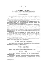
Equation (4.2) has a special physical meaning. In essence, there are now
two mmfs at standstill (fixed) with sinusoidal spatial distribution and sinusoidal
currents. The space angle lag and the time angle between the two mmfs is π/2.
This suggests that a pure traveling mmf may be produced with two symmetrical
windings π/2 shifted in time (Figure 41.a). This is how the two phase induction
machine evolved.
Similarly, we may decompose (4.1) into 3 terms
()
π
+ω
π
+θ−
τ
π
+
+
π
−ω
π
−θ−
τ
π
+ω
θ−
τ
π
=
3
2
tcos
3
2
xcos
3
2
tcos
3
2
xcostcosxcosF
3
2
t,xF
10
1010m1s1s
(4.3)
Consequently, three mmfs (single-phase windings) at standstill (fixed) with
sinusoidal spatial (x) distribution and departured in space by 2π/m radians, with
sinusoidal symmetrical currents−equal amplitude, 2π/3 radians time lag
angle−are also able to produce also a traveling mmf (Figure 4.1.b).
In general, m phases with a phase lag (in time and space) of 2π/3 can
produce a traveling wave. Six phases (m = 6) would be a rather practical case
besides m = 3 phases. The number of mmf electrical periods per one revolution
is called the number of pole pairs p
1
.2,4,6,8, 2p ;
2
D
p
11
=
τ
π
=
(4.4)
where D is the stator bore diameter.
It should be noted that, for p
1
> 1, according to (4.4), the electrical angle α
e
is p
1
times larger than the mechanical angle α
g
g1e
p α=α
(4.5)
A sinusoidal distribution of mmfs (ampereturns) would be feasible only
with the slotless machine and windings placed in the airgap. Such a solution is
hardly practical for induction machines because the magnetization of a large
© 2002 by CRC Press LLC
Author: Ion Boldea, S.A.Nasar………… ………
total airgap would mean very large magnetization mmf and, consequently, low
power factor and efficiency. It would also mean problems with severe
mechanical stress acting directly on the electrical conductors of the windings.
x
sin x/
πτ
τ
θ
= 0
0
x
cos x/
πτ
a.)
ω
t
π2π
1
I (t)
A
I (t)
B
ω
t
1
π2π
x
cos x/
πτ
x
x 2
ππ
x
τ
τ
3
()
cos
x 2
ππ
τ
3
()
cos
ω
t
1
ω
t
1
ω
t
1
π2π
π2π
π2π
I (t)
B
I (t)
A
I (t)
C
-i /2
max
-i /2
max
b.)
2p
τ
1
2p
τ
1
2p
τ
1
2p
τ
1
2p
τ
1
Figure 4.1 Ideal multiphase mmfs
a.) two-phase machine b.) three-phase machine
In practical induction machines, the coils of the windings are always placed
in slots of various shapes (Chapter 2).
The total number of slots per stator N
s
should be divisible by the number of
phases m so that
integerm/N
s
=
(4.6)
A parameter of great importance is the number of slots per pole per phase q:
mp2
N
q
1
s
=
(4.7)
The number q may be an integer (q = 1,2, … 12) or a fraction.
In most induction machines, q is an integer to provide complete (pole to
pole) symmetry for the winding.
The windings are made of coils. Lap and wave coils are used for induction
machines (Figure 4.2).
The coils may be placed in slots in one layer (Figure 4.2a) or in two layers
(Figure 4.3.b).
© 2002 by CRC Press LLC
Author: Ion Boldea, S.A.Nasar………… ………
y
τ
<
>
a x
11
y
τ
>
<
a
11
x
a.) b.)
Figure 4.2 Lap a.). and wave b.) single-turn (bar) coils
a
1
x
1
stack length
a
1
x
1
end
connections
Figure 4.3 Single-layer a.) and double-layer b.) coils (windings)
Single layer windings imply full pitch (y = τ) coils to produce an mmf
fundamental with pole pitch
τ
.
Double layer windings also allow chorded (or fractional pitch) coils (y < τ)
such that the end connections of coils are shortened and thus copper loss is
reduced. Moreover, as shown later in this chapter, the harmonics content of
mmf may be reduced by chorded coils. Unfortunately, so is the fundamental.
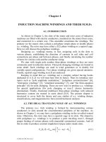
4.3. A PRIMITIVE SINGLE-LAYER WINDING
Let us design a four pole (2p
1
= 4) three-phase single-layer winding with q
= 1 slots/pole/phase. N
s
= 2p
1
qm = 2·2·1·3 = 12 slots in all.
From the previous paragraph, we infer that for each phase we have to
produce an mmf with 2p
1
= 4 poles (semiperiods). To do so, for a single layer
winding, the coil pitch y = τ = N
s
/2p
1
= 12/4 = 3 slot pitches.
For 12 slots there are 6 coils in all. That is, two coils per phase to produce 4
poles. It is now obvious that the 4 phase A slots are y = τ = 3 slot pitches apart.
We may start in slot 1 and continue with slots 4, 7, and 10 for phase A (Figure
4.4a).
Phases B and C are placed in slots by moving 2/3 of a pole (2 slots pitches
in our case) to the right. All coils/phases may be connected in series to form one
current path (a = 1) or they may be connected in parallel to form two current
paths in parallel (a = 2). The number of current paths a is obtained in general by
connecting part of coils in series and then the current paths in parallel such that
all the current paths are symmetric. Current paths in parallel serve to reduce
wire gauge (for given output phase current) and, as shown later, to reduce
© 2002 by CRC Press LLC
Author: Ion Boldea, S.A.Nasar………… ………
uncompensated magnetic pull between rotor and stator in presence of rotor
eccentricity.
A
1
1
Z
1
2
B
1
3
X
1
4
C
1
5
Y
1
6
A
2
7
Z
2
8
B
2
9
X
2
10
C
2
11
Y
2
12
a.)
pole pitch:
τ
b
os
slot
pitch
τ
s
2τ/3
n i
cs
A
b.)
n i
cs
B
n i
cs
C
c.)
x
A
1
X ,A
12
X
2
Y
2
Z
2
Z ,C
1
2
C
1
Y ,B
1
2
B
1
a=1
A
1
A
2
X
1
X
2
Z
1
Z
2
C
1
C
2
Y
1
Y
2
B
1
B
2
a=2
e.)
f.)
Figure 4.4 Single-layer three-phase winding for 2p
1
= 4 poles and q = 1 slots/pole/phase: a.)
slot/phase allocation;
b.), c.), d.) ideal mmf distribution for the three phases when their currents are maximum;
e.) star series connection of coils/phase; f.) parallel connection of coils/phase
If the slot is considered infinitely thin (or the slot opening b
os
≈ 0), the mmf
(ampereturns) jumps, as expected, by n
cs
⋅i
A,B,C
, along the middle of each slot.
For the time being, let us consider b
os
= 0 (a virtual closed slot).
The rectangular mmf distribution may be decomposed into harmonics for
each phase. For phase A we simply obtain
()
τ
νπ
ν
ω
⋅
π
=
x
cos
tcos2In
2
t,xF
1cs
1A
(4.8)
© 2002 by CRC Press LLC
Author: Ion Boldea, S.A.Nasar………… ………
For the fundamental, ν = 1, we obtain the maximum amplitude. The higher
the order of the harmonic, the lower its amplitude in (4.8).
While in principle such a primitive machine works, the harmonics content is
too rich.
It is only intuitive that if the number of steps in the rectangular ideal
distribution would be increased, the harmonics content would be reduced. This
goal could be met by increasing q or (and) via chording the coils in a two-layer
winding. Let us then present such a case.
4.4. A PRIMITIVE TWO-LAYER CHORDED WINDING
Let us still consider 2p
1
= 4 poles, m = 3 phases, but increase q from 1 to 2.
Thus the total number of slots N
s
= 2p
1
qm = 2·2·2·3 = 24.
The pole pitch τ measured in slot pitches is τ = N
s
/2p
1
= 24/4 = 6. Let us
reduce the coil throw (span) y such that y = 5τ/6.
We still have to produce 4 poles. Let us proceed as in the previous
paragraph but only for one layer, disregarding the coil throw.
In a two, layer winding, the total number of coils is equal to the number of
slots. So in our case there are N
s
/m = 24/3 coils per phase. Also, there are 8 slots
occupied by one phase in each layer, four with inward and four with outward
current direction. With each layer each phase has to produce four poles in our
case. So slots 1, 2; 7’, 8’; 13, 14; 19’, 20’ in layer one belong to phase A. The
superscript prime refers to outward current direction in the coils. The distance
between neighbouring slot groups of each phase in one layer is always equal to
the pole pitch to preserve the mmf distribution half-period (Figure 4.5).
Notice that in Figure 4.5, for each phase, the second layer is displaced to the
left by τ-y = 6-5 = 1 slot pitch with respect to the first layer. Also, after two
poles, the situation repeats itself. This is typical for a fully symmetrical winding.
Each coil has one side in one layer, say, in slot 1, and the second one in slot
y + 1 = 5 + 1 = 6. In this case all coils are identical and thus the end connections
occupy less axial room and are shorter due to chording. Such a winding is
typical with random wound coils made of round magnetic wire.
For this case we explore the mmf ideal resultant distribution for the
situation when the current in phase A is maximum (i
A
= i
max
). For symmetrical
currents, i
B
= i
C
= −i
max
/2 (Figure 4.1b).
Each coil has n
c
conductors and, again with zero slot opening, the mmf
jumps at every slot location by the total number of ampereturns. Notice that half
the slots have coils of same phase while the other half accommodate coils of
different phases.
The mmf of phase A, for maximum current value (Figure 4.5b) has two
steps per polarity as q = 2. It had only one step for q = 1 (Figure 4.4). Also, the
resultant mmf has three unequal steps per polarity (q + τ-y = 2 + 6-5 = 3). It is
indeed closer to a sinusoidal distribution. Increasing q and using chorded coils
reduces the harmonics content of the mmf.
© 2002 by CRC Press LLC
Author: Ion Boldea, S.A.Nasar………… ………
A
A
1
A
C’
2
C’
C’
3
C’
B
4
B
B
5
B
A’
6
A’
A’
7
A’
C
8
C
C
9
C
B’
10
B’
B’
11
B’
A
12
A
A
13
A
C’
14
C’
C’
15
C’
B
16
B
B
17
B
A’
18
A’
A’
19
A’
C
20
C
C
21
C
B’
22
B’
B’
23
B’
A
24
2n i
F (x,t)
i =i =I 2
i =i =-I /2
F (x,t)+F (x,t)+F (x,t)
2/3
π
ABC
max
c
A
n i
max
c
A
F (x,t)+F (x,t)+F (x,t)
ABC
max
i =i =I 2
A
max
B
C
max
i =i =-I /2
i =i =I 2
B
max
A
C
max
a.)
b.)
Figure 4.5 Two-layer winding for Ns = 24 slots, 2 p
1
= 4 poles, y/τ = 5/6
a.) slot/phase allocation, b.) mmfs distribution
Also shown in Figure 4.5 is the movement by 2
τ
/3 (or 2
π
/3 electrical
radians) of the mmf maximum when the time advances with 2π/3 electrical
(time) radians or T/3 (T is the time period of sinusoidal currents).
4.5. THE MMF HARMONICS FOR INTEGER q
Using the geometrical representation in Figure 4.5, it becomes fairly easy to
decompose the resultant mmf in harmonics noticing the step-form of the
distributions.
Proceeding with phase A we obtain (by some extrapolation for integer q),
()
tcosxcosKK2qIn
2
t,xF
11y1qc1A
ω
τ
π
π
=
(4.9)
with
()
1/y
2
sinK;1q6/sinq/6/sinK
1y1q
≤τ
π
=≤ππ=
(4.10)
K
q1
is known as the zone (or spread) factor and K
y1
the chording factor. For q =
1, Kq1 = 1 and for full pitch coils, y/τ = 1, K
y1
= 1, as expected.
To keep the winding fully symmetric y/τ ≥ 2/3. This way all poles have a
similar slot/phase allocation.
Assuming now that all coils per phase are in series, the number of turns per
phase W
1
is
© 2002 by CRC Press LLC
Author: Ion Boldea, S.A.Nasar………… ………
c11
qnp2W =
(4.11)
With (4.11), Equation (4.9) becomes
()
tcosxcosKK2IW
p
2
t,xF
11y1q1
1
1A
ω
τ
π
π
=
(4.12)
For three phases we obtain
()
ω−
τ
π
= txcosFt,xF
1m1
1
(4.13)
with
1
1y1q1
m1
p
KK2IW3
F
π
=
(ampereturns per pole) (4.14)
The derivative of pole mmf with respect to position x is called linear current
density (or current sheet) A (in Amps/meter)
()
()
ω+
τ
π
−=
∂
∂
= txsinA
x
t,xF
t,xA
1m1
1
1
(4.15)
m1
1
1y1q1
m1
F
p
KK2IW23
A
τ
π
=
τ
=
(4.16)
A
1m
is the maximum value of the current sheet and is also identified as current
loading. The current loading is a design parameter (constant) A
1m
≈ 5,000A/m to
50,000 A/m, in general, for induction machines in the power range of kilowatts
to megawatts. It is limited by the temperature rise and increases with machine
torque (size).
The harmonics content of the mmf is treated in a similar manner to obtain
()
() ()
π
+ν−ω+
τ
νπ
−
π
−ν−ω−
τ
νπ
⋅
⋅
νπ
=
νν
3
2
1txcosK
3
2
1txcosK
p
KK2IW3
t,xF
1BII1BI
1
yq1
(4.17)
with
τ
νπ
=
νπ
νπ
=
νν
2
y
sinK;
q6/sinq
6/sin
K
yq
(4.18)
()
()
()
()
3/1sin3
1sin
K;
3/1sin3
1sin
K
BIIBI
π+ν
π+ν
=
π−ν
π−ν
=
(4.19)
© 2002 by CRC Press LLC
Author: Ion Boldea, S.A.Nasar………… ………
Due to mmf full symmetry (with q = integer), only odd harmonics occur.
For three-phase star connection, 3K harmonics may not occur as the current sum
is zero and their phase shift angle is 3K⋅2π/3 = 2πK.
We are left with harmonics ν = 3K ± 1; that is ν = 5, 7, 11, 13, 17, … .
We should notice in (4.19) that for ν
d
= 3K + 1, K
BI
= 1 and K
BII
= 0. The
first term in (4.17) represents however a direct (forward) traveling wave as for a
constant argument under cosinus, we do obtain
11
11
f2;
f2
dt
dx
π=ω
ν
τ
=
πν
τω
=
(4.20)
On the contrary, for
ν
= 3K-1, K
BI
= 0, and K
BII
= 1. The second term in
(4.17) represents a backward traveling wave. For a constant argument under
cosinus, after a time derivative, we have
ν
τ−
=
πν
τω−
=
−=ν
11
1K3
f2
dt
dx
(4.21)
We should also notice that the traveling speed of mmf space harmonics, due
to the placement of conductors in slots, is ν times smaller than that of the
fundamental (ν = 1).
The space harmonics of the mmf just investigated are due both to the
placement of conductors in slots and to the placement of various phases as
phase belts under each pole. In our case the phase belts spread is π/3 (or one
third of a pole). There are also two layer windings with 2π/3 phase belts but the
π
/3 (60
0
) phase belt windings are more practical.
So far the slot opening influences on the mmf stepwise distribution have not
been considered. It will be discussed later in this chapter.
Notice that the product of zone (spread or distribution) factor K
q
ν
and the
chording factor K
y
ν
is called the stator winding factor K
w
ν
.
ννν
=
yqw
KKK
(4.22)
As in most cases, only the mmf fundamental (ν = 1) is useful, reducing most
harmonics and cancelling some is a good design attribute. Chording the coils to
cancel K
y
ν
leads to
3
2y
;n
2
y
;0
2
y
sin
>
τ
π=
τ
νπ
=
τ
νπ
(4.23)
As the mmf harmonic amplitude (4.17) is inversely proportional to the
harmonic order, it is almost standard to reduce (cancel) the fifth harmonic (ν =
5) by making n = 2 in (4.23).
5
4y
=
τ
(4.23’)
© 2002 by CRC Press LLC
Author: Ion Boldea, S.A.Nasar………… ………
In reality, this ratio may not be realized with an integer q (q = 2) and thus
y/τ = 5/6 or 7/9 is the practical solution which keeps the 5th mmf harmonic low.
Chording the coils also reduces K
y1
. For y/τ = 5/6,
0.1966.0
6
5
2
sin
<=
π
but a
4% reduction in the mmf fundamental is worth the advantages of reducing the
coil end connection length (lower copper losses) and a drastical reduction of 5
th
mmf harmonic.
Mmf harmonics, as will be shown later in the book, produce parasitic
torques, radial forces, additional core and winding losses, noise, and vibration.
Example 4.1.
Let us consider an induction machine with the following data: stator core
diameter D = 0.1 m, number of stator slots N
s
= 24, number of poles 2p
1
= 4, y/τ
= 5/6, two-layer winding; slot area A
slot
= 100 mm
2
, total slot fill factor K
fill
=
0.5, current density j
Co
= 5 A/mm
2
, number of turns per coil n
c
= 25. Let us
calculate
a.) The rated current (RMS value), wire gauge
b.) The pole pitch τ
c.) K
q1
and K
y1
, K
w1
d.) The amplitude of the mmf F
1m
and of the current sheet A
1m
e.) K
q7
, K
y7
and F
7m
(ν = 7)
Solution
Part of the slot is filled with insulation (conductor insulation, slot wall
insulation, layer insulation) because there is some room between round wires.
The total filling factor of a slot takes care of all these aspects. The mmf per slot
is
Aturns25055.0100JKAIn2
Cofillslotc
=⋅⋅=⋅⋅=
As n
c
= 25; I = 250/(2⋅25) = 5A (RMS). The wire gauge d
Co
is:
mm 128.1
5
54
J
I4
d
Co
Co
=
π
=
π
=
The pole pitch τ is
m 11775.0
22
15.0
p2
D
1
=
⋅
⋅π
=
π
=τ
From (4.10)
9659.0
26
sin2
6
sin
K
1q
=
⋅
π
π
=
© 2002 by CRC Press LLC
Author: Ion Boldea, S.A.Nasar………… ………
933.0966.09659.0KKK ;966.0
6
5
2
sinK
1y1qw11y
=⋅===⋅
π
=
The mmf fundamental amplitude, (from 4.14), is
phase/turns20025222qnp2W
c11
=⋅⋅⋅==
pole/Aturns628
2
933.0252003
p
K2IW3
F
1
1w1
m1
=
⋅π
⋅⋅⋅
=
π
=
From (4.16) the current sheet (loading) A
1m
is,
m/Aturns3.13155
15.0
628FA
m1m1
=
π
⋅=
τ
π
=
From (4.18),
()
()
2588.0
6
5
6
7
sinK ;2588.0
26/7sin2
6/7sin
K
7y7q
=⋅
π
=−=
⋅π
π
=
066987.02588.02588.0K
w7
−=⋅−=
From (4.18),
pole/Aturns445.6
72
066987.0252003
7p
KK2IW3
F
1
7y7q1
m7
=
⋅⋅π
⋅⋅⋅
=
π
=
This is less than 1% of the fundamental F
1m
= 628Aturns/pole.
It may be shown that for 120
0
phase belts [10], the distribution (spread)
factor K
q
ν
is
()
()
q3/sinq
3/sin
K
q
⋅νπ
πν
=
ν
(4.24)
For the same case q = 2 and ν = 1, we find K
q1
= sinπ/3 = 0.867. This is
much smaller than 0.9659, the value obtained for the 60
0
phase belt, which
explains in part why the latter case is preferred in practice.
Now that we introduced ourselves to a.c. windings through two case
studies, let us proceed and develop general rules to design practical a.c.
windings.
4.6. RULES FOR DESIGNING PRACTICAL A.C. WINDINGS
The a.c. windings for induction motors are usually built in one or two
layers.
The basic structural element is represented by coils. We already pointed out
(Figure 4.2) that there may be lap and wave coils. This is the case for single turn
(bar) coils. Such coils are made of continuous bars (Figure 4.6a) for open slots
© 2002 by CRC Press LLC
Author: Ion Boldea, S.A.Nasar………… ………
or from semibars bent and welded together after insertion in semiclosed slots
(figure 4.6b).
wedge
open
slot
a.)
semi-bar
wedge
semiclosed slot
bent after
insertion
into the slot
b.)
Figure 4.6 Bar coils: a.) continuous bar, b.) semi bar
These are preformed coils generally suitable for large machines.
Continuous bar coils may also be made from a few elementary conductors
in parallel to reduce the skin effect to acceptable levels.
On the other hand, round-wire, mechanically flexible coils forced into
semiclosed slots are typical for low power induction machines.
Such coils may have various shapes such as shown in Figure 4.7.
A few remarks are in order.
• Wire-coils for single layer windings, typical for low power induction
motors (kW range and 2p
1
= 2pole) have in general wave-shape;
• Coils for single layer windings are always full pitch as an average
• The coils may be concentrated or identical
• The main concern should be to produce equal resistance and leakage
inductance per phase
• From this point of view, rounded concentrated or chain-shape identical
coils are to be preferred for single layer windings
Double-layer winding coils for low power induction machines are of
trapezoidal shape and round shape wire type (Figure 4.8a, b).
For large power motors, preformed multibar (rectangular wire) (Figure
4.8c) or unibar coils (Figure 4.6) are used.
Now to return to the basic rules for a.c. windings design let us first
remember that they may be integer q or fractional q (q = a+b/c) windings with
the total number of slots N
s
= 2p
1
qm. The number of slots per pole could be
only an integer. Consequently, for a fractional q, the latter is different and
integer for a phase under different poles. Only the average q is fractional.
Single-layer windings are built only with an integer q.
As one coil sides occupy 2 slots, it means that N
s
/2m = an integer (m–
number of phases; m = 3 in our case) for single-layer windings. The number of
inward current coil sides is evidently equal to the number of outward current
coil sides.
© 2002 by CRC Press LLC
Author: Ion Boldea, S.A.Nasar………… ………
For two-layer windings the allocation of slots per phase is performed in one
(say, upper) layer. The second layer is occupied “automatically” by observing
the coil pitch whose first side is in one layer and the second one in the second
layer. In this case it is sufficient to have N
s
/m = an integer.
q=2
a.)
1 2 7 8
storeI
II
III
stator
stack
end connections
q=2
b.)
1 2
7 8
τ
=6slot
pitches=
=Y average
q=2
c.)
1 2 7 8
end connections
Figure 4.7 Full pitch coil groups/phase/pole−for q = 2−for single layer a.c. windings:
a.) with concentrated rectangular shape coils and 2 (3) store end connections;
b.) with concentrated rounded coils; c.) with chain shape coils.
A pure traveling stator mmf (4.13), with an open rotor winding and a
constant airgap (slot opening effects are neglected), when the stator and iron
core permeability is infinite, will produce a no-load ideal flux density in the
airgap as
()
ω−
τ
π
µ
= txcos
g
F
t,xB
1
m10
10g
(4.25)
according to Biot – Savart law.
This flux density will self-induce sinusoidal emfs in the stator windings.
© 2002 by CRC Press LLC
Author: Ion Boldea, S.A.Nasar………… ………
The emf induced in coil sides placed in neighboring slots are thus phase
shifted by α
es
s
1
es
N
p2
π
=α
(4.26)
a.)
wedge
slot filling
y<
τ
R
b.)
open slot
filling
preformed wound
coil with
rectangular conductors
end connections
Figure 4.8 Typical coils for two-layer a.c. windings:
a. trapezoidal flexible coil (round wire);
b. rounded flexible coil (rounded wire);
c. preformed wound coil (of rectangular wire) for open slots.
The number of slots with emfs in phase, t, is
t = greatest common divisor (Ns,p
1
) = g.c.d. (N
s
,p
1
) ≤ p
1
(4.27)
Thus the number of slots with emfs of distinct phase is N
s
/t. Finally the
phase shift between neighboring distinct slot emfs α
et
is
s
et
N
t2π
=α
(4.28)
If α
es
= α
et
, that is t = p
1
, the counting of slots in the emf phasor star
diagram is the real one in the machine.
© 2002 by CRC Press LLC
Author: Ion Boldea, S.A.Nasar………… ………
Now consider the case of a single winding with N
s
= 24, 2p
1
= 4. In this
case
624
22
N
p2
s
1
es
π
=
⋅π
=
π
=α
(4.29)
t = g.c.d. (N
s
,p
1
) = g.c.d.(24,2) = 2 = p
1
(4.30)
So the number of distinct emfs in slots is N
s
/t = 24/2 = 12 and their phase
shift α
et
= α
es
= π/6. So their counting (order) is the natural one (Figure. 4.9).
13
14
1
2
A
17
18
5
6
B
21
22
9
10
C
23
24
11 12
B’
15
16
3
4
C’
19
20
7
8
A’
α α π
==/6
es
et
Figure 4.9 The star of slot emf phasors for a single-layer winding
with q = 2, 2p
1
= 3, m = 3, N
s
= 24 slots.
The allocation of slots to phases to produce a symmetric winding is to be
done as follows for
single-layer windings
•
Built up the slot emf phasor star based on calculating
α
et
,
α
es
, N
s
/t
distinct arrows counting them in natural order after α
es
.
• Choose randomly N
s
/2m successive arrows to make up the inward
current slots of phase A (Figure 4.9).
• The outward current arrows of phase A are phase shifted by π radians
with respect to the inward current ones.
• By skipping N
s
/2m slots from phase A, we find the slots of phase B.
•
Skipping further N
s
/2m slots from phase B we find the slots of phase C.
double-layer windings
• Build up the slot emf phasor star as for single-layer windings.
• Choose N
s
/m arrows for each phase and divide them into two groups
(one for inward current sides and one for outward current sides) such
that they are as opposite as possible.
• The same routine is repeated for the other phases providing a phase
shift of 2π/3 radians between phases.
It is well understood that the above rules are also valid for the case of
fractional q. Fractional q windings are built only in two-layers and small q, to
reduce the order of first slot harmonic.
© 2002 by CRC Press LLC
Author: Ion Boldea, S.A.Nasar………… ………
Placing the coils in slots
For single-layer, full pitch windings, the inward and outward side coil
occupy entirely the allocated slots from left to right for each phase. There will
be N
s
/2m coils/phase.
The chorded coils of double-layer windings, with a pitch y (2
τ
/3
≤
y <
τ
for
integer q and single pole count windings) are placed from left to right for each
phase, with one side in one layer and the other side in the second layer. They are
connected observing the inward (A, B, C) and outward (A’, B’, C’) directions of
currents in their sides.
Connecting the coils per phase
The N
s
/2m coils per phase for single-layer windings and the N
s
/m coils per
phase for double-layer windings are connected in series (or series/parallel) such
that for the first layer the inward/outward directions are observed. With all
coils/phase in series, we obtain a single current path (a = 1). We may obtain “a”
current paths if the coils from 2p
1
/a poles are connected in series and, then, the
“a ” chains in parallel.
Example 4.2. Let us design a single-layer winding with 2p
1
= 2 poles, q = 4, m
= 3 phases.
Solution
1
24
23
22
21
20
19
18
17
16
15
14
13
12
11
10
9
8
7
6
5
4
3
2
A
B’
C
A’
B
C’
Figure 4.10 The star of slot emf phasors for a single-layer winding: q = 1, 2p
1
= 2, m = 3, N
s
= 24.
The angle α
es
(4.26), t (4.27), α
et
(4.28) are
24qmp2N
1s
==
;
1224
12
N
P2
s
1
es
π
=
⋅π
=
π
=α
t = g.c.d.(N
s
, P
1
) = g.c.d.(24,1) = 1
© 2002 by CRC Press LLC
Author: Ion Boldea, S.A.Nasar………… ………
1224
12
N
t2
s
et
π
=
⋅π
=
π
=α
Also the count of distinct arrows of slot emf star N
s
/t = 24/1 = 24.
Consequently the number of arrows in the slot emf star is 24 and their order
is the real (geometrical) one (1, 2, … 24)–Figure 4.10.
Making use of Figure 4.10, we may thus alocate the slots to phases as in
Figure 4.11.
A A A A C’ B A’ C C C C B’C’ C’ C’ B B B A’ A’ A’ B’ B’ B’
a.)
1 2 3 4 5 6 7 8 9 1011 12 13 1415 16 1718 19 20 2122 23 24
AX
b.)
16’
1
15’
2
14’
3
13’
4
24’
9
23’
10
22’
11
21’
12
20
5’
19
6’
18
7’
17
8’
A
X
Y
Z
C
B
n
cs
conductors per
slot (half coils slot)
Figure 4.11 Single-layer winding layout
a.) slot/phase allocation; b.) rounded coils of phase A; c.) coils per phase
© 2002 by CRC Press LLC
Author: Ion Boldea, S.A.Nasar………… ………
Example 4.3. Let us consider a double-layer three-phase winding with q = 3,
2p
1
= 4, m = 3, (Ns = 2p
1
qm = 36 slots), chorded coils y/τ = 7/9 with a = 2
current paths.
Solution
Proceeding as explained above, we may calculate α
es
, t, α
et
:
936
22
N
P2
s
1
es
π
=
⋅π
=
π
=α
t = g.c.d.(36,2) = 2
1,19
18,36
17,35
16,34
15,33
14,32
13,31
12,30
11,29
10,28
9,27
8,26
7,25
6,24
5,23
4,22
3,21
2,20
A
B’
C
A’
B
C’
Figure 4.12 The star of slot emf phasors for a double-layer winding (one layer shown) with 2p
1
= 4
poles,
q = 3 slots/pole/phase, m = 3, N
s
= 36
182/36t/N
936
22
N
t2
ses
s
et
==α=
π
=
⋅π
=
π
=α
There are 18 distinct arrows in the slot emf star as shown in Figure 4.12.
The winding layout is shown in Figure 4.13. We should notice the second
layer slot allocation lagging by τ – y = 9 – 7 = 2 slots, the first layer allocation.
Phase A produces 4 fully symmetric poles. Also, the current paths are fully
symmetric. Equipotential points of two current paths U – U’, V – V’, W – W’
could be connected to each other to handle circulating currents due to, say, rotor
eccentricity.
© 2002 by CRC Press LLC
Author: Ion Boldea, S.A.Nasar………… ………
A A A C’C’C’ B B B A’ A’ A’ C C C B’ B’ B’ A A A
1
2
3
4
5
6
7
8
9
10
11
12
13
14
15
16
17
18
19
20
21
22
23
24
25
26
27
28
29
30
31
32
33
34
35
36
C’ C’ C’ B B B A’ A’ A’ C C C B’ B’ B’
A C ’ C ’ C ’ B B B A’ A’ A’ C C C B ’ B ’ B ’ A A A C’ C’ C ’ B B B A’ A’ A’ C C C B ’ B ’ B’ A A
layer1
layer2
1
2
3
4
5
6
7
8
9
10
11
12
13
14
15
16
17
18
19
20
21
22
23
24
25
26
27
28
29
30
31
32
33
34
35
36
O
to X
from O
A X
3-10’
2-9’
A
X
1-8’
17-10’18-11’19-12’
21-28’
20-27’19-26’
35-28’36-29’1-30’
U
U’
equipotential
connection
B
Y
V
V’
equipotential
connection
C
Z
W
W’
equipotential
connection
2a=2 current paths
Figure 4.13 Double-layer winding: 2p
1
= 4 poles, q = 3, y/τ = 7/9, N
s
= 36 slots, a = 2 current paths.
Having two current paths, the current in the coils is half the current at the
terminals. Consequently, the wire gauge of conductors in the coils is smaller and
thus the coils are more flexible and easier to handle.
Note that using wave coils is justified in single-bar coils to reduce the external
leads to one by which the coils are connected to each other in series. Copper,
labor, and space savings are the advantages of this solution.
4.7. BASIC FRACTIONAL q THREE-PHASE A.C. WINDINGS
Fractional q a.c. windings are not typical for induction motors due to their
inherent pole asymmetry as slot/phase allocation under adjacent poles is not the
same in contrast to integer q three-phase windings. However, with a small q (q ≤
© 2002 by CRC Press LLC
Author: Ion Boldea, S.A.Nasar………… ………
3) to reduce the harmonics content of airgap flux density, by increasing the
order of the first slot harmonic from 6q ± 1 for integer q to 6(ac + b) ± 1 for q =
(ca + b)/c = fractional two-layer such windings are favoured to single-layer
versions. To set the rules to design such a standard winding–with identical
coils–we proceed with an example.
Let us consider a small induction motor with 2p
1
= 8 and q = 3/2, m = 3.
The total number of slots N
s
= 2p
1
qm = 2⋅4⋅3/2⋅3 = 36 slots. The coil span y is
y = integer(N
s
/2p
1
) = integer(36/8) = 4slot pitches (4.31)
The parameters t, α
es
, α
et
are
t = g.c.d.(N
s
, p
1
) = g.c.d.(36,4) = 4 = p
1
(4.33)
et
s
1
es
9
2
36
8
N
p2
α=
π
=
⋅π
=
π
=α
(4.34)
The count of distinct arrows in the star of slot emf phasors is N
s
/t = 36/4 =
9. This shows that the slot/phase allocation repeats itself after each pole pair (for
an integer q it repeats after each pole). Thus mmf subharmonics, or fractional
space harmonics, are still absent in this case of fractional q. This property holds
for any q = (2l + 1)/2 for two-layer configurations.
The star of slot emf phasors has q arrows and the counting of them is the
natural one (α
es
= α
et
) (Figure 4.14a).
A few remarks in Figure 4.14 are in order
• The actual value of q for each phase under neighboring poles is 2 and 1,
respectively, to give an average of 3/2
• Due to the periodicity of two poles (2τ), the mmf distribution does not
show fractional harmonics (ν <1 )
• There are both odd and even harmonics, as the positive and negative
polarities of mmf (Figure 4.14c) are not fully symmetric
•
Due to a two pole periodicity we may have a = 1 (Figure 4.14d), or a = 2, 4
• The chording and distribution (spread) factors (K
y1
, K
q1
) for the
fundamental may be determined from Figure 4.14e using simple phasor
composition operations.
()
π
=
1s
s
1
1y
p2/Negerint
N
p
sinK
(4.35)
3
N
t
cos21
K
s
1q
π
+
=
(4.36)
This is a kind of general method valid both for integer and fractional q.
© 2002 by CRC Press LLC
Author: Ion Boldea, S.A.Nasar………… ………
Extracting the fundamental and the space harmonics of the mmf distribution
(Figure 4.14c) takes implicit care of these factors both for the fundamental and
for the harmonics.
1,10
19,28
9,18
27,36
8,17
26,35
7,16
25,34
6,15
24,33
5,14
23,32
4,13
22,31
3,12
21,30
2,11
20,29
A
C’
B
A’
C
B’
a.)
A A C’ B B A’ C C B’
1
2
3
4
5
6
7
8
9
10
11
12
13
14
15
16
17
18
19
20
21
22
23
24
25
26
27
28
29
30
31
32
33
34
35
36
AAC’BBA’CCB’AAC’BBA’CCB’AAC’BBA’CCB’
A C’ C’B A’ A’ C B’B’A C’ C’ B A’ A’ C B’ B’A C’ C’ B A’ A’ C B’ B’A C’ C’ B A’ A’ C B’ B’
b.
)
N
S
N
S
N
S
N
S
F
(
x,t
)
=F
(
x,t
)
+F
(
x,t
)
+F
(
x,t
)
; i =I ;i =i =-I /2
AB C CBAmax max
c.)
d.)
N
S
N
S
N
S
N
S
A X
© 2002 by CRC Press LLC
Author: Ion Boldea, S.A.Nasar………… ………
E
i
E
o
E
i
E
o
E
ch
α
Integer(N /2p )
es s
α
et
E
1
E
2
E
6’
E
6’
-
E
q
1
Figure 4.14 Fractionary q (q = 3/2, 2p
1
= 8, m = 3, N
s
= 36) winding
a.) emf star, b.) slot/phase allocation, c.) mmf,
d.) coils of phase A, e.) chording and spread factors
4.8. BASIC POLE-CHANGING THREE-PHASE A.C. WINDINGS
From (4.20) the speed of the mmf fundamental dx/dt is
1
1
f2
dt
dx
τ=
=ν
(4.37)
The corresponding angular speed is
1
1
1
1
1
1
p
f
n ;
p
f2
D
2
dt
dx
=
π
==Ω
(4.38)
The mmf fundamental wave travels at a speed n
1
= f
1
/p
1
. This is the ideal
speed of the motor with a cage rotor.
Changing the speed may be accomplished either by changing the frequency
(through a static power converter) or by changing the number of poles.
Changing the number of poles to produce a two-speed motor is a traditional
method. Its appeal is still strong today due to low hardware costs where
continuous speed variation is not required. In any case, the rotor should have a
squirrel cage to accommodate both pole pitches. Even in variable speed drives
with variable frequency static converters, when a very large constant power
speed range (over 2(3) to 1) is required, such a solution should be considered to
avoid a notable increase in motor weight (and cost).
Two – speed induction generators are also used for wind energy conversion
to allow a notable speed variation to extract more energy from the wind speed.
There are two possibilities to produce a two-speed motor. The most obvious
one is to place two distinct windings in the slots. The number of poles would be
2p
1
> 2p
2
. However the machine becomes very large and costly, while for the
winding placed on the bottom of the slots the slot leakage inductance will be
very large with all due consequences.
© 2002 by CRC Press LLC
Author: Ion Boldea, S.A.Nasar………… ………
1 13
7 19
6 18
5 17
4 16
3 15
2 14
12 24
11 23
10 22
9 21
8 20
A
C’
B
A’
C
B’
α =α =π/6
et
es
a.)
A A C’C’ B B A’ A’ C C B’B’ A A C’ C’B B A’ A’ C C B’B’
1
2
3
4
5
6
7
8
9
10
11
12
13
14
15
16
17
18
19
20
21
22
23
24
AAC’C’BBA’A’CCB’B’AAC’C’BBA’A’CCB’B’
b.)
A
2
A
1
X
1
X
2
2p =4
2
(A and X for 2P =2)
221
N
S
N
S
N
S
N
S
1
2
3
456789
10
11
12
13
14 1516 1718 1920
21
22
23
24
2n i
c
max
i =i
i =i =-i /2
C
B
A
max
max
(when i is
maximum)
A
N
S
N
F(x,t)
2p =2
1
2p =4
1
F(x,t)
Figure 4.15 2/4 pole winding (N
s
= 24)
a.) emf star, b.) slot/phase allocation, c.) coils of phase A, d.), e.) mmf for 2p
2
= 4 and 2p
1
= 2
© 2002 by CRC Press LLC
Author: Ion Boldea, S.A.Nasar………… ………
Using a pole-changing winding seems thus a more practical solution.
However standard pole-changing windings have been produced mainly for
2p
1
/2p
2
= 1/2 or 2p
1
/2p
2
= 1/3.
The most acclaimed winding has been invented by Dahlander and bears his
name.
In essence the current direction (polarity) in half of a 2p
2
pole winding is
changed to produce only 2p
1
= 2p
2
/2 poles. The two-phase halves may be
reconnected in series or parallel and Y or ∆ connections of phases is applied.
Thus, for a given line voltage and frequency supply, with various such
connections, constant power or constant torque or a certain ratio of powers for
the two speeds may be obtained.
Let us now proceed with an example and consider a two-layer three-phase
winding with q = 2, 2p
2
= 4, m = 3, N
s
= 24slots, y/τ = 5/6 and investigate the
connection changes to switch it to a two pole (2p
1
= 2) machine.
The design of such a winding is shown on Figure 4.15. The variables are t =
g.c.d(N
s
, p
2
) = 2 = p
2
, α
es
= α
et
= 2πp
2
/N
s
= π/6, and N
s
/t = 12. The star of slot
emf phasors is shown in Figure 5.15a.
Figure 4.15c illustrates the fact that only the current direction in the section
A2 -–X2 of phase A is changed to produce a 2p
1
= 2 pole winding. A similar
operation is done for phases B and C.
A possible connection of phase halves called ∆/2Y is shown in Figure 4.16.
It may be demonstrated that for the ∆ (2p
2
= 4)/2Y (2p
1
= 2) connection, the
power obtained for the two speeds is about the same.
We also should notice that with chorded coils for 2p
2
= 4 (y/τ = 5/6), the
mmf distribution for 2p
1
= 2 has a rather small fundamental and is rich in
harmonics.
C
2
Z
1
Z
2
C
1
X
1
A
2
A
1
X
2
Y
1
B
2
B
1
Y
2
2p =4
2
A
B
C
∆
C
2
Z
1
Z
2
C
1
X
1
A
2
A
1
X
2
Y
1
B
2
B
1
Y
2
2p =2
1
B
A
C
2Y
Figure 4.16 2/4 pole winding connection for constant power
© 2002 by CRC Press LLC
Author: Ion Boldea, S.A.Nasar………… ………
In order to achieve about the same winding factor for both pole numbers,
the coil span should be greater than the pole pitch for the large number of poles
(y = 7, 8 slot pitches in our case). Even if close to each other, the two winding
factors are, in general, below 0.85.
The machine is thus larger than usual for the same power and care must be
exercised to maintain the acceptable noise level.
Various connections of phases may produce designs with constant torque
(same rated torque for both speeds) or variable torque. For example, a Y – YY
parallel connection for 2p
2
/2p
1
= 2/1 is producing a ratio of power P
2
/P
1
= 0.35
– 0.4 as needed for fan driving. Also, in general, when switching the pole
number we may need modify the phase sequence to keep the same direction of
rotation.
One may check if this operation is necessary by representing the stator mmf
for the two cases at two instants in time. If the positive maximum of the mmfs
advances in time in opposite directions, then the phase sequence has to be
changed.
4.9. TWO-PHASE A.C. WINDINGS
When only single phase supply is available, two-phase windings are used.
One is called the main winding (M) and the other, connected in series with a
capacitor, is called the auxiliary winding (Aux).
The two windings are displaced from each other, as shown earlier in this
chapter, by 90
0
(electrical), and are symmetrized for a certain speed (slip) by
choosing the correct value of the capacitance. Symmetrization for start (slip = 0)
with a capacitance Cstart and again for rated slip with a capacitance C
run
is
typical (Cstart >> C
run
).
When a single capacitor is used, as a compromise between acceptable
starting and running, the two windings may be shifted in space by more than 90
0
(105
0
to 110
0
) (Figure 4.17).
~
γ
Aux
C
start
C
run
γ=90 ( )
general
γ=105 −110
0
00
~
1
2
a.)
b.)
Figure 4.17 Two-phase induction motor
a.) for unidirectional motion,
b.) for bidirectional motion (1 - closed for forward motion; 2 - closed for backward motion)
© 2002 by CRC Press LLC