the induction machine handbook chuong (17)
Bạn đang xem bản rút gọn của tài liệu. Xem và tải ngay bản đầy đủ của tài liệu tại đây (298.43 KB, 31 trang )
Chapter 17
INDUCTION MACHINE DESIGN FOR VARIABLE SPEED
17.1 INTRODUCTION
Variable speed drives with induction motors are by now a mature
technology with strong and dynamic markets for applications in all industries.
Based on the load torque/speed envelope, three main types of applications may
be distinguished:
• Servodrives: no constant power speed range
• General drives: moderate constant power speed range (ω
max
/ω
b
≤ 2)
• Constant power drives: large constant power speed range (ω
max
/ω
b
≥ 2)
Servodrives for robots, machine tools, are characterized, in general, by
constant torque versus speed up to base speed ω
b
. The base speed ω
b
is the
speed for which the motor can produce (for continuous service) for rated
voltage and rated temperature rise, the rated (base) power P
b
, and rated torque
T
eb
.
Servodrives are characterized by fast torque and speed response and thus
for short time, during transients, the motor has to provide a much higher torque
T
ek
than T
eb
. The higher the better for speed response quickness. Also
servodrives are characterized by sustained very low speed and up to rated (base)
torque operation, for speed or position control. In such conditions, low torque
pulsations and limited temperature rise are imperative.
Temperature rise has to be limited to avoid both winding insulation failure
and mechanical deformation of the shaft which would introduce errors in
position control.
In general, servodrives have a constant speed (separate shaft) power, grid
fed, ventilator attached to the IM at the non-driving end. The finned stator frame
is thus axially cooled through the ventilator’s action. Alternatively, liquid
cooling of the stator may be provided.
Even from such a brief introduction, it becomes clear that the design
performance indexes of IMs for servodrives need special treatment. However,
fast torque and speed response and low torque pulsations are paramount.
Efficiency and power factor are second order performance indexes as the
inverter KVA rating is designed for the low duration peak torque (speed)
transients requirements.
General drives, which cover the bulk of variable speed applications, are
represented by fans, pumps, compressors, etc.
General drives are characterized by a limited speed control range, in
general, from 0.1ω
b
to 2ω
b
. Above base speed ω
b
constant power is provided. A
limited constant power speed range ω
max
/ω
b
= 2.0 is sufficient for most cases.
Above base speed, the voltage stays constant.
© 2002 by CRC Press LLC
Author: Ion Boldea, S.A.Nasar………… ………
Based on the stator voltage circuit equation at steady state,
s
1s
s
s
jRIV Ψω+=
(17.1)
with Rs ≈ 0
1
s
s
V
ω
≈Ψ
(17.2)
Above base speed (ω
b
), the frequency ω
1
increases for constant voltage.
Consequently, the stator flux level decreases. Flux weakening occurs. We might
say that general drives have a 2/1-flux weakening speed range.
As expected, there is some torque reserve for fast acceleration and braking
at any speed. About 150% to 200% overloading is typical.
General drives use IMs with on-the-shaft ventilators. More sophisticated
radial-axial cooling systems with a second cooling agent in the stator may be
used.
General drives may use high efficiency IM designs as in this case efficiency
is important.
Made with class F insulated preformed coils and insulated bearings for
powers above 100 kW and up to 2000 kW, and at low voltage (maximum 690
V), such motors are used in both constant and variable speed applications.
While designing IMs on purpose for general variable speed drives is possible, it
may seem more practical to have a single design both for constant and variable
speed: the high efficiency induction motor.
Constant power variable speed applications
, such as spindles or hybrid
(or electric) car propulsion, generator systems, the main objective is a large flux
weakening speed range ω
max
/ω
b
> 2, in general more than 3–4 , even 6–7 in
special cases. Designing an IM for a wide constant power speed range is very
challenging because the breakdown torque T
bk
is in p.u. limited: t
bk
< 3 in
general.
sc
2
1
ph
1
eK
L
1
V
2
p3
T ⋅
ω
≈
(17.3)
Increasing the breakdown torque as the base speed (frequency) increases
could be done by
• Decreasing the pole number 2p
1
• Increasing the phase voltage
• Decreasing the leakage inductance L
sc
(by increased motor size,
winding tapping, phase connection changing, special slot (winding)
designs to reduce L
sc
)
Each of these solutions has impact on both IM and static power
converter costs. The global cost of the drive and the capitalized cost of
its losses are solid criteria for appropriate designs. Such applications
are most challenging. Yet another category of variable speed
applications is represented by super-high speed drives.
© 2002 by CRC Press LLC
Author: Ion Boldea, S.A.Nasar………… ………
• For fast machine tools, vacuum pumps etc., speeds which imply
fundamental frequencies above 300 Hz (say above 18,000 rpm) are
considered here for up to 100 kW powers and above 150 Hz (9000
rpm) for higher powers.
As the peripheral speed goes up, above (60–80) m/s, the mechanical
constraints become predominant and thus novel rotor configurations become
necessary. Solid rotors with copper bars are among the solutions considered in
such applications. Also, as the size of IM increases with torque, high-speed
machines tend to be small (in volume/power) and thus heat removal becomes a
problem. In many cases forced liquid cooling of the stator is mandatory.
Despite worldwide efforts in the last decade, the design of IMs for variable
speed, by analytical and numerical methods, did not crystallize in widely
accepted methodologies.
What follows should be considered a small step towards such a daring goal.
As basically the design expressions and algorithms developed for constant
V/f (speed) are applicable to variable speed design, we will concentrate only on
what distinguishes this latter enterprise.
• In the end, a rather detailed design example is presented. Among the
main issues in IM design for variable speed, we treat here
• Power and voltage derating
• Reducing skin effect
• Reducing torque pulsations
• Increasing efficiency
• Approaches to leakage inductance reduction
• Design for wide constant power wide speed range
• Design for variable very high speed
17.2 POWER AND VOLTAGE DERATING
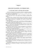
An induction motor is only a part of a variable speed drive assembly (Figure
17.1).
As such, the IM is fed from the power electronics converter (PEC) directly,
but indirectly, in most cases, from the industrial power grid.
3 ~
50 (60) Hz
Power
electronics
converter
(PEC)
IM
Load
machine
Figure 17.1 Induction machine in a variable speed drive system
There are a few cases where the PEC is fed from a dc source (battery).
The PEC inflicts on the motor voltage harmonics (in a voltage source type)
or current harmonics (in a current source type). In this way, voltage and current
© 2002 by CRC Press LLC
Author: Ion Boldea, S.A.Nasar………… ………
harmonics, whose frequency and amplitude are dependent on the PWM
(control) strategy and power level, are imposed on the induction motor.
Additionally, high frequency common voltage mode currents may occur in
the stator phases in high frequency PWM voltage source converter IM drives.
All modern PECs have incorporated filtering methods to reduce the additional
current and voltage (flux) harmonics in the IMs as they produce additional
losses.
Analytical and even finite element methods have been proposed to cater to
these time harmonics losses (see Chapter 11). Still, these additional time
harmonics core and winding losses depend not only on machine geometry and
materials, but also on PWM, switching frequency and load level. [1,2]
On top of this, for given power grid voltage, the maximum fundamental
voltage at motor terminals depends on the type of PEC (single or double stage,
type of power electronics switches (PES)) and PWM (control) strategy.
Though each type of PEC has its own harmonics and voltage drop
signature, the general rule is that lately both these indexes have decreased. The
matrix converter is a notable exception in the sense that its voltage derating
(drop) is larger (up to 20%) in general.
Voltage derating – less than 10%, in general 5%–means that the motor
design is performed at a rated voltage V
m
which is smaller than the a.c. power
grid voltage V
g
:
(
)
1.0v;v1VV
derderatgm
<−=
(17.4)
Power derating comes into play in the design when we choose the value of
Esson’s constant C
0
(W/m
3
), as defined by past experience for sinusoidal power
supply, and reduce it to C
0
’
for variable V/f supply:
() ( )
12.008.0p;p1CC
deratderat0
'
0
−≈−=
(17.5)
It may be argued that this way of handling the PEC-supplied IM design is
quite empirical. True, but this is done only to initiate the design (sizing) process.
After the sizing is finished, the voltage drops in the PEC and the time harmonics
core and winding losses may be calculated (see Chapter 11). Then design
refinements are done. Alternatively, if prototyping is feasible, test results are
used to validate (or correct) the loss computation methodologies.
There are two main cases: one when the motor exists, as designed for
sinusoidal power supply, and the other when a new motor is to be designed for
the scope.
The derating concepts serve both these cases in the same way.
However, the power derating concept is of little use where no solid past
experience exists, such as in wide constant power speed range drives or in
super-high speed drives. In such cases, the tangential specific force (N/cm
2
),
Chapter 14, with limited current sheet (or current density) and flux densities,
seem to be the right guidelines for practical solutions. Finally, the temperature
rise and performance (constraints) checks may lead to design iterations. As
© 2002 by CRC Press LLC
Author: Ion Boldea, S.A.Nasar………… ………
already mentioned in Chapter 14, the rated (base) tangential specific force (σ
t
)
for sinusoidal power supply is
()
2sin
t
cm/N0.43.0
−≈σ
(17.6)
Derating now may be applied to σ
t
sin
to get σ
t
PEC
()
derat
sin
t
PEC
t
p1 −σ=σ
(17.7)
for same rated (base) torque and speed.
The value of σ
t
PEC
increases with rated (base) torque and decreases with
base speed.
17.3 REDUCING THE SKIN EFFECT IN WINDINGS
In variable speed drives, variable V and f are used. Starting torque and
current constraints are not relevant in designing the IM. However, for fast
torque (speed) response during variable frequency and voltage starting or
loading or for constant power wide speed range applications, the breakdown
torque has to be large.
Unfortunately, increasing the breakdown torque without enlarging the
machine geometry is not an easy task.
On the other hand, rotor skin effect that limits the starting current and
produces larger starting torque, based on a larger rotor resistance is no longer
necessary.
Reducing skin effect is now mandatory to reduce additional time harmonics
winding losses.
Skin effect in winding losses depends on frequency, conductor size, and
position in slots. First, the rotor and stator skin effect at fundamental frequency
is to be reduced. Second, the rotor and stator skin effect has to be checked and
limited at PEC switching frequency. The amplitude of currents is larger for the
fundamental than for time harmonics. Still the time harmonics conductor losses
at large switching frequencies are notable. In super-high speed IMs the
fundamental frequency is already large, (300-3(5)000) Hz. In this case the
fundamental frequency skin effects are to be severely checked and kept under
control for any practical design as the slip frequency may reach tenth of Hz (up
to 50-60 Hz).
As the skin effect tends to be larger in the rotor cage we will start with this
problem.
Rotor bar skin effect reduction
The skin effect is a direct function of the parameter:
2
S
h
0cor1
µσω
=ζ
(17.8)
The slot shape also counts. But once the slot is rectangular or circular, only
the slot diameter, and respectively, the slot height counts.
© 2002 by CRC Press LLC
Author: Ion Boldea, S.A.Nasar………… ………
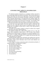
Rounded trapezoidal slots may also be used to secure constant tooth flux
density and further reduce the skin effects (Figure 17.2).
d
r
b
h
h
b
b /3
α ∼ 30
h
d = d
d = d /3
d
2
1
r
1
r
2
1
r
r
r
r1
or
d
0
b = d
r
r
a.) b.) c.)
Figure 17.2 Rotor bar slots with low skin effect
a.) round shape b.) rectangular c.) pear-shape
For given rotor slot (bar) area A
b
(Figure17.2 a,b,c), we have
()
2
r1r
ror
1rr
r
2
r
b
d
36
5
d
3
2
h
db
2
h
3
d2
h
4
d
A
π
+=
++⋅=
π
=
(17.9)
For the rectangular slot, the skin effect coefficients K
r
and K
x
have the
standard formulas
ζ−ζ
ζ−ζ
ζ
=
ζ−ζ
ζ+ζ
ζ=
2cos2cosh
2sin2sinh
2
3
K
2cos2cosh
2sin2sinh
K
X
R
(17.10)
In contrast, for round or trapezoidal-round slots, the multiple-layer
approach of Chapter 9, has to be used.
A few remarks are in order:
• As expected, for given geometry and slip frequency, skin effects are
more important in copper than in aluminum bars
• For given rotor slot area, the round bar has limited use
• As the bar area (bar current or motor torque) increases, the maximum
slip frequency f
r
= Sf
1
for which K
R
< 1.1 diminishes
• Peak slip frequency f
srk
varies from 2 Hz to 10 Hz
• The smaller values correspond to larger (MW) machines and larger
values to subKW machines designed for base frequencies of 50 (60)
Hz. For f
srK
, K
R
< 1.1 has to be fulfilled if rotor additional losses are to
© 2002 by CRC Press LLC
Author: Ion Boldea, S.A.Nasar………… ………
be limited. Consequently, the maximum slot depth depends heavily on
motor peak torque requirements
• For super-high speed machines, f
srk
may reach even 50 (60) Hz, so
extreme care in designing the rotor bars is to be exercised (in the sense
of severe limitation of slot depth, if possible)
• Maintaining reduced skin effect at f
srK
means, apparently, less deep
slots and thus, for given stator bore diameter, longer lamination stacks.
As shown in the next paragraph this leads to slightly lower leakage
inductances, and thus to larger breakdown torque. That is, a beneficial
effect.
• When the rotor skin effect for f
srK
may not be limited by reducing the
slot depth, we have to go so far as to suggest the usage of a wound
rotor with shortcircuited phases and mechanically enforced end-
connections against centrifugal forces
• To reduce the skin effect in the end rings, they should not be placed
very close to the laminated stack, though their heat transmission and
mechanical resilience is a bit compromised
• Using copper instead of aluminium leads to a notable reduction of rotor
bar resistance for same bar cross-section though the skin effect is
larger. A smaller copper bar cross-section is allowed, for same
resistance as aluminum, but for less deep slots and thus smaller slot
leakage inductance. Again, larger breakdown torque may be obtained.
The extracost of copper may prove well worth while due to lower
losses in the machine.
•
As the skin effect is maintained low, the slot-body geometrical specific
permeance λ
sr
for the three cases mentioned earlier (Figure 17.1) is:
4.0
d2
h
db
33
2
b3
h
666.0
r
r
trap
sr
rr
r
r
rect
sr
round
sr
+≈λ
=
+≈λ
≈λ
(17.11)
Equations (17.11) suggest that, in order to provide for identical slot
geometrical specific permeance λ
sr
, h
r
/b
r
≤ 1.5 for the rectangular slot and h
r
/d
r
< 0.5 for the trapezoidal slot. As the round part of slot area is not negligible, this
might be feasible (h
r
/d
r
≈ π/8 < 0.5), especially for low torque machines.
Also for the rectangular slot with b
r
= d
r
, h
r
= (π/4) d
r
<< 1.5, so the
rectangular slot may produce
()
round
sr
root
st
67.033/212/4/ λ≈=+π=πλ
(17.11′)
In reality, as the rated torque gets larger, the round bar is difficult to adopt
as it would lead to a too small number of rotor slots or too a larger rotor
© 2002 by CRC Press LLC
Author: Ion Boldea, S.A.Nasar………… ………
diameter. In general, a slot aspect ratio h
r
/b
r
≤ 3 may be considered acceptable
for many practical cases.
• The skin effect in the stator windings, at least for fundamental
frequencies less than 100(120) Hz is negligible in well designed IMs
for all power levels. For large powers, elementary rectangular cross
section conductors in parallel are used. They are eventually stranded in
the end-connection zone. The skin effect and circulating current
additional losses have to be limited in large motors
• In super-high speed IMs, for fundamental frequencies above 300 Hz
(up to 3 kHz or more), stator skin effect has to be carefully investigated
and suppressed by additional methods such as Litz wire, or even by
using thin wall pipe conductors with direct liquid cooling when needed
• Skin-effect stator and rotor winding losses at PWM inverter carrier
frequency are to be calculated as shown in Chapter 11, paragraph
11.12.
17.4 TORQUE PULSATIONS REDUCTION
Torque pulsations are produced both by airgap flux density space harmonics
in interaction with stator (rotor) m.m.f. space harmonics and by voltage
(current) time harmonics produced by the power electronics converter (PEC)
which supplies the IM to produce variable speed.
As torque time harmonics pulsations depend mainly on the PEC type and
power level we will not treat them here. The space harmonic torque pulsations
are produced by the so called parasitic torques (see Chapter 10). They are of two
categories: asynchronous and synchronous and depend on the number of rotor
and stator slots, slot opening/airgap ratios and airgap/pole pitch ratio, and the
degree of saturation of stator (rotor) core. They all however occur at rather large
values of slip: S > 0.7 in general.
This fact seems to suggest that for pump/fan type applications, where the
minimum speed hardly goes below 30% base speed, the parasitic torques occur
only during starting.
Even so, they should be considered, and the same rules apply, in choosing
stator rotor slot number combinations, as for constant V and f design (Chapter
15, table 15.5).
• As shown in Chapter 15, slot openings tend to amplify the parasitic
synchronous torques for N
r
> N
s
(N
r
– rotor slot count, N
s
– stator slot
count). Consequently N
r
< N
s
appears to be a general design rule for
variables V and f, even without rotor slot skewing (for series connected
stator windings).
• Adequate stator coil throw chording (5/6) will reduce drastically
asynchronous parasitic torque.
• Carefully chosen slot openings to mitigate between low parasitic
torques and acceptable slot leakage inductances are also essential.
• Parasitic torque reduction is all the more important in servodrive
applications with sustained low (even very low) speed operation. In
© 2002 by CRC Press LLC
Author: Ion Boldea, S.A.Nasar………… ………
such cases, additional measures such as skewed resin insulated rotor
bars and eventually closed rotor slots and semiclosed stator slots are
necessary. FEM investigation of parasitic torques may become
necessary to secure sound results.
17.5 INCREASING EFFICIENCY
Increasing efficiency is related to loss reduction. There are fundamental
core and winding losses and additional ones due to space and time harmonics.
Lower values of current and flux densities lead to a larger but more efficient
motor. This is why high efficiency motors are considered suitable for variables
V and f.
Additional core losses and winding losses have been treated in detail in
Chapter 11.
Here we only point out that the rules to reduce additional losses, presented
in Chapter 11 still hold. They are reproduced here and extended for convenience
and further discussion.
• Large number of slots/pole/phase in order to increase the order of the
first slot space harmonic
• Insulated or uninsulated high bar-slot wall contact resistance rotor bars
in long stack skewed rotors, to reduce interbar current losses
• Skewing is not adequate for low bar-slot wall contact resistance as it
does not reduce the harmonics (stray) cage losses while it does increase
interbar current losses
• 0.8N
s
< N
r
< N
s
– to reduce the differential leakage coefficient of the
first slot harmonics (N
s
± p
1
), and thus reduce the interbar current
losses
• For N
r
< N
s
skewing may be altogether eliminated after parasitic torque
levels are checked. For q = 1,2 skewing seems mandatory
• Usage of thin special laminations (0.1 mm) above f
1n
= 300Hz is
recommended to reduce core loss in super-high speed IM drives
• Chorded coils (y/τ ≈ 5/6) reduce the asynchronous parasitic torque
produced by the first phase belt harmonic (υ = 5)
• With delta connection of stator phases: (N
s
– N
r
) ≠ 2p
1
, 4p
1
, 8p
1
.
• With parallel paths stator windings, the stator interpath circulating
currents produced by rotor bar current m.m.f. harmonics have to be
avoided by observing certain symmetry of stator winding paths
• Small stator (rotor) slot openings lead to smaller surface and tooth flux
pulsation additional core losses but they tend to increase the leakage
inductances and thus reduce the breakdown torque
• Carefully increase the airgap to reduce additional core and cage losses
without compromising too much the power factor and efficiency
• Use sharp tools and annealed laminations to reduce surface core losses
• Return core losses rotor surface to prevent rotor lamination
shortcircuits which would lead to increased rotor surface core losses
© 2002 by CRC Press LLC
Author: Ion Boldea, S.A.Nasar………… ………
• Use only recommended N
s
, N
r
combinations and check for parasitic
torque and stray load levels
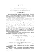
• To reduce the time and space harmonics losses in the rotor cage, U
shape bridge rotor slots have been proposed (Figure 17.3). [3]
Al
(copper)
Al
(copper)
h
iron bridge
b
a.) b.) c.)
Figure 17.3 Rotor slot designs
a) conventional b) straight bridge closed slot c) u-bridge close slot
In essence in conventional rotor slots, the airgap flux density harmonics
induce voltages which produce eddy currents in the aluminium situated in the
slot necks. By providing a slit in the rotor laminations (Figure 17.3b, 17.3c), the
rotor conductor is moved further away from the airgap and thus the additional
cage losses are reduced.
However, this advantage comes with three secondary effects.
First, the eddy currents in the aluminium cage close to airgap damp the
airgap flux density variation on the rotor surface and in the rotor tooth. This, in
turn, limits the rotor core surface and tooth flux pulsation core losses.
In our new situation, it no longer occurs. Skewed rotor slots seem
appropriate to keep the rotor surface and tooth flux pulsation core losses under
control.
Second, the iron bridge height h
b
above the slot, even when saturated, leads
to a notable additional slot leakage geometrical permeance coefficient: λ
b
.
Consequently, the value of L
sc
is slightly increased, leading to a breakdown
torque reduction.
Third, the mechanical resilience of the rotor structure is somewhat reduced
which might prevent the usage of this solution to super-high speed IMs.
17.6 INCREASING THE BREAKDOWN TORQUE
As already inferred, a large breakdown torque is desirable either for high
transient torque reserve or for widening the constant power speed range.
Increasing the breakdown torque boils down to leakage inductance
decreasing, when the base speed and stator voltage are given (17.3).
The total leakage inductance of the IM contains a few terms as shown in
Chapter 6.
© 2002 by CRC Press LLC
Author: Ion Boldea, S.A.Nasar………… ………
The stator and rotor leakage inductances are (Chapter 6)
()
enddszsss11
2
si0sl
qpnL2L λ+λ+λ+λ⋅µ=
(17.12)
n
s
– conductors slot
()
()
skewdrzrerbi0
r
2
1W1
1rl
L2
N
KW
m4L λ+λ+λ+λ+λµ×=
(17.13)
m
1
– number of phases
L
i
– stack length
q
1
– slots/pole/phase
λ
ss
– stator slot permeance coefficient
λ
zs
– stator zig-zag permeance coefficient
λ
ds
– stator differential permeance coefficient
λ
end
– stator differential permeance coefficient
λ
b
– rotor slot permeance coefficient
λ
er
– end ring permeance coefficient
λ
zr
– rotor zig-zag permeance coefficient
λ
dr
– rotor differential permeance coefficient
λ
skew
– rotor skew leakage coefficient
The two general expressions are valid for open and semi-closed slots. For
closed rotor slots λ
b
has the slot iron bridge term as rotor current dependent.
With so many terms, out of which very few may be neglected in any
realistic analysis, it becomes clear that an easy sensitivity analysis of L
sl
and L
rl
to various machine geometrical variables is not easy to wage.
The main geometrical variables which influence L
sc
= L
sl
+L
rl
are
• Pole number: 2p
1
• Stack length/pole pitch ratio: L
i
/τ
• Slot/tooth width ratio: b
s1r
/b
ts1r
• Stator bore diameter
• Stator slots/pole/phase q
1
• Rotor slots/pole pair N
r
/p
1
• Stator (rotor) slot aspect ratio h
ss1r
/b
s1r
• Airgap flux density level B
g
• Stator (rotor) base torque (design) current density
Simplified sensitivity analysis [4] of j
cos
, j
Al
to t
sc
(or t
bk
– breakdown torque in
p.u.) have revealed that 2,4,6 poles are the main pole counts to consider except
for very low direct speed drives – conveyor drives – where even 2p
1
= 12 is to
be considered, only to eliminate the mechanical transmission.
Globally, when efficiency, breakdown torque, and motor volume are all
considered, the 4 pole motor seems most desirable.
Reducing the number of poles to 2p
1
= 2, for given speed n
1
= f
1
/p
1
(rps)
means lower frequency, but for the same stator bore diameter, it means larger
pole pitch and longer end connections and thus, larger λ
end
in (17.12).
© 2002 by CRC Press LLC
Author: Ion Boldea, S.A.Nasar………… ………
Now with q
1
larger, for 2p
1
= 2 the differential leakage coefficient λ
ds
is
reduced. So, unless the stack length is not small at design start (pancake shape),
the stator leakage inductance (17.12) decreases by a ratio of between 1 and 2
when the pole count increases from 2 to 4 poles, for the same current and flux
density. Considering the two rotors identical, with the same stack length, L
rl
in
(17.13) would not be much different. This leads us to the peak torque formula
(17.3).
()
1
ph
sph
sc
2
sph
1
ek
V
;
L22
p3
T
ω
=Ψ
Ψ
≈
(17.14)
For the same number of stator slots for 2p
1
= 2 and 4, conductors per slot n
s
,
same airgap flux density, and same stator bore diameter, the phase flux linkage
ratio in the two cases is
(
)
()
1
2
4p2
sph
2p2
sph
1
1
=
Ψ
Ψ
=
=
(17.15)
as the frequency is doubled for 2p
1
= 4, in comparison with 2p
1
= 2, for the
same no load speed (f
1
/p
1
).
Consequently,
()
()
8.15.1
L
L
4p2
sc
2p2
sc
1
1
−=
=
=
(17.16)
Thus, for the same bore diameter, stack length, and slot geometry,
()
()
8.15.1
2
T
T
4p2
ek
2p2
ek
1
1
−
≈
=
=
(17.17)
From this simplified analysis, we may draw the conclusion that the 2p
1
= 2
pole motor is better. If we consider the power factor and efficiency, we might
end up with a notably better solution.
For super-high speed motors, 2p
1
= 2 seems a good choice (f
1n
> 300 Hz).
For a given total stator slot area (same current density and turns/phase), and
the same stator bore diameter, increasing q
1
(number of slot/pole/phase) does
not essentially influence L
sl
(17.12) – the stator slot leakage and end connection
leakage inductance components – as n
s
p
1
q
1
= W
1
= ct and slot depth remains
constant while the slot width decreases to the extent q
1
increases, and so does
λ
end
()
1end
i
end
qy64.0l
L
34.0
⋅⋅−≈λ
(17.18)
with l
end
= end connection length; y – coil throw; L
i
– stack length.
© 2002 by CRC Press LLC
Author: Ion Boldea, S.A.Nasar………… ………
However, λ
ds
decreases and apparently so does λ
zs
. In general, with larger
q
1
, the total stator leakage inductance will decrease slightly. In addition, the
stray losses have been proved to decrease with q
1
increasing.
A similar rationale is valid for the rotor leakage inductance L
rl
(17.13)
where the number of rotor slots increases. It is well understood that the
condition 0.8N
s
< N
r
< N
s
is to be observed.
A safe way to reduce the leakage reactance is to reduce the slot aspect ratio
h
ss,r
/b
ss,r
< 3.0-3.5. For given current density this would lead to lower q
1
(or N
s
)
for a larger bore diameter, that is, a larger machine volume.
However, if the design current density is allowed to increase (sacrificing to
some extent the efficiency) with a better cooling system, the slot aspect ratio
could be kept low to reduce the leakage inductance L
sc
.
A low leakage (transient) inductance L
sc
is also required for current source
inverter IM drives. [4]
So far, we have considered same current and flux densities, stator bore
diameter, stack length, but the stator and yoke radial height for 2p
1
= 2 is
doubled with respect to the 4 pole machine.
(
)
()
()
1
25.1
h
h
4p2
r,cs
2p2
r,cs
1
1
−
≈
=
=
(17.19)
Even if we oversaturated the stator and rotor yokes, and more for the two
pole machine, the outer stator diameter will still be larger in the latter. It is true
that this leads to a larger heat exchange area with the environment, but still the
machine size is larger.
So, when the machine size is crucial, 2p
1
= 4 [5] even 2p
1
= 6 is chosen
(urban transportation traction motors).
Whether to use long or short stack motors is another choice to make in the
pursuit of smaller leakage inductance L
sc
. Long stator stacks may allow smaller
stator bore diameters, smaller pole pitches and thus smaller stator end
connections.
Slightly smaller L
sc
values are expected. However, a lower stator (rotor)
diameter does imply deeper slots for the same current density. An increase in
slot leakage occurs.
Finally, increasing the stack length leads to limited breakdown torque
increase.
When low inertia is needed, the stack length is increased while the stator
bore diameter is reduced. The efficiency will vary little, but the power factor
will likely decrease. Consequently, the PEC KVA rating has to be slightly
increased. The KVA ratings for two pole machines with the same external stator
diameter and stack length, torque and speed, is smaller than for a 4 pole
machine because of higher power factor. So when the inverter KVA is to be
limited, the 2 pole machine might prevail.
A further way to decrease the stator leakage inductance may be to use four
layers (instead of two) and chorded coils to produce some cancelling of mutual
© 2002 by CRC Press LLC
Author: Ion Boldea, S.A.Nasar………… ………
leakage fluxes between them. The technological complication seems to render
such approaches as less than practical.
17.7 WIDE CONSTANT POWER SPEED RANGE VIA VOLTAGE
MANAGEMENT
Constant power speed range varies for many applications from 2 to 1 to 5(6)
to 1 or more.
The obvious way to handle such requirements is to use an IM capable to
produce, at base speed ω
b
, a breakdown torque T
bk
:
ω
=
ω
ω
=
C
T
T
b
max
en
bk
(17.20)
•
A larger motor
In general, IMs may not develop a peak to rated torque higher than 2.5 (3)
to 1 (Figure 17.4a).
In the case when a large constant power speed range C
ω
is required, it is
only intuitive to use a larger IM (Figure 17.4b).
Adopting a larger motor, to have enough torque reserve up to maximum
speed for constant power may be done either with an IM with 2p
1
= 2,4 of
higher rating or a larger number of pole motor with the same power. While such
a solution is obvious for wide constant power speed range (C
ω
> 2.0 – 3.0), it is
not always acceptable as the machine size is notably increased.
3
2
1
T
T = T
en
eb
ek
T > T
ek
en
ω
ω
max
b
T > T
bk
eb
ω
ω
max
b
T < T
eb
en
T < T
en
eb
ω
max
ω
max
ω
b
T
en
T
bk
T
e
ω
b
T
en
(
)
ω
ω
max
b
T
eb
(
)
ω
ω
max
b
b.)larger motor: > 3.0
ω
ω
max
b
ω
ω
max
b
a.)fullsize motor: < 3.0
T
e
T
en
Figure 17.4 Torque-speed envelope for constant power
a) full size motor b) larger motor
© 2002 by CRC Press LLC
Author: Ion Boldea, S.A.Nasar………… ………
•
Higher voltage/phase
The typical torque/speed, voltage/speed, and current/speed envelopes for
moderate constant power speed range are shown on Figure 17.5.
The voltage is considered constant above base speed. The slip frequency f
sr
is rather constant up to base speed and then increases up to maximum speed. Its
maximum value f
srmax
should be less or equal to the critical value (that
corresponding to breakdown torque)
sc
r
maxsrsr
L2
R
ff
π
=≤
(17.21)
ω
max
ω
b
ω
ω
max
b
voltage
torque
power
current
voltage
current
torque
power
f = S f
f
sr
1
srmax
~
~
(
2.0 - 3
)
Figure 17.5 Torque, voltage, current versus frequency
()
max
b
eb
sc
2
maxr
ph
1
max
bk
T
L
1
V
p
2
3
T
ω
ω
⋅≥⋅
ω
=
ω
(17.22)
If
()
max
b
eb
max
bk
TT
ω
ω
<
ω
, (17.23)
it means that the motor has to be oversized to produce enough torque at
maximum speed.
If a torque (power reserve) is to be secured for fast transients, a larger
torque motor is required.
Alternatively, the phase voltage may be increased during the entire constant
power range (Figure 17.6)
To provide a certain constant overloading over the entire speed range, the
phase voltage has to increase over the entire constant power speed range. This
© 2002 by CRC Press LLC
Author: Ion Boldea, S.A.Nasar………… ………
means that for base speed ω
b
, the motor will be designed for lower voltage and
thus larger current. The inverter current loading (and costs) will be increased.
ω
ω
max
b
peak torque
rated torque
voltage
V
T
ω
max
ω
b
ω
C =
V
T
T
T
T
= C
~
~
ω
ω
max
b
=
e
bp
b
b
M
Mp
M
T
bp
T
b
bt
T
M
T
b
1
C
ω
=
T
M
p
T
M
Mt
C
Figure 17.6 Raising voltage for the constant power speed range
Let us calculate the torque T
e
, and stator current I
s
from the basic
equivalent circuit.
08.102.1
L
L
1C;LCLL
;
L
s
R
CR
s/RV
p3
T
m
sl
1rl1sl
'
sc
2'
sc
2
1
2
r
1s
r
2
ph
1
1
e
−≈+=+=
ω+
+
⋅
⋅
ω
≈
(17.24)
2'
sc
2
1
2
r
1s
2
m1
phs
L
s
R
CR
1
L
1
VI
ω+
+
+
ω
≈
(17.25)
At maximum speed, the machine has to develop the peak torque T
Mp
at
maximum voltage V
M
.
Now if for both T
bp
and T
Mp
, the breakdown torque conditions are met,
sc
2
max
M1
Mp
sc
2
b
b
1
bP
L2
1V
2
p3
T
L2
1
V
2
p3
T
⋅
ω
=
⋅
ω
=
, (17.26)
the voltage ratios V
M
/V
b
is (as in [6])
© 2002 by CRC Press LLC
Author: Ion Boldea, S.A.Nasar………… ………
bt
Mt
b
bp
M
Mp
b
max
bp
Mp
2
b
max
2
b
M
C
C
C
T
T
T
T
T
T
V
V
ω
=
⋅
ω
ω
=
ω
ω
=
(17.27)
For ω
max
/ω
b
= 4, C
Mt
= 1.5, C
bt
= 2.5, we find from (17.17) that V
M
/V
b
=
1.55. So the current rating of the inverter (motor) has to be increased by 55%.
Such a solution looks extravagant in terms of converter extra-costs, but it
does not suppose IM overrating (in terms of power). Only a special design for
lower voltage V
b
at base speed ω
b
is required.
For
2'
sc
2
M,b
2
s
r1
K,b,m
LR
RC
SS
ω+
==
(17.28)
and ω
1
= ω
b
and, respectively, ω
1
= ω
M
from (17.25), the corresponding base
and peak current values I
b
, I
M
may be obtained.
These currents are to be used in the motor (I
b
) and converter
(
)
2I
M
design.
Now, based on the above rationale, the various cases, from constant
overloading C
MT
= C
bt
to zero overloading at maximum speed C
MT
= 1, may be
treated in terms of finding V
M
/V
b
and I
M
/I
b
ratios and thus prepare for motor and
converter design (or selection). [6]
As already mentioned, reducing the slot leakage inductance components
through lower slot aspect ratios may help to increase the peak torque by as much
as (50–60%) in some cases, when forced air cooling with a constant speed fan is
used. [6]
•
High constant power speed range: ω
max
/ω
b
> 4
For a large constant power speed range, the above methods are not
generally sufficient. Changing the phase voltage by switching motor phase
connection from star to delta (Y to ∆) leads to a sudden increase in phase
voltage by
.3
A notably larger constant power speed range is obtained this
way (Figure 17.7).
The Y to ∆ connection switching has to be done through a magnetic switch
with the PEC control temporarily inhibited and then so smoothly reconnected
that no notable torque transients occurred. This voltage change is done “on the
fly.”
An even larger constant power speed range extension may be obtained by
using a winding tap (Figure 17.8) to switch from a large to a small number of
turns per phase (from W
1
to W’
1
, W
1
/W’
1
= C
W1
>1).
A double single-throw magnetic switch suffices to switch from high (W
1
) to
low number of turns (W
1
/C
W1
) for high speed.
© 2002 by CRC Press LLC
Author: Ion Boldea, S.A.Nasar………… ………
Y connection
∆
power
speed
ω
max
∆
ω
b
maxY
ω
ω
max
∆
maxY
ω
= ( 3 ) = 3
2
Figure 17.7 Extended constant power speed range by Υ to ∆ stator connection switching
Once the winding is designed with the same current density for both
winding sections, the switching from W
1
to W
1
/C
W1
turns leads to stator and
rotor resistance reduction by C
W1
> 1 times and a total leakage inductance L
sc
reduction by C
2
W1
.
Low speed
terminal
High speed
terminal
A
A
B
B
C
C
L
H
L
H
H
L
1
w
1
W /C
W
Figure 17.8 Tapped stator winding
In terms of peak (breakdown torque), it means a strong increase by C
2
W1
.
The constant power speed range is extended by
2
W
Lmax
Hmax
1
C=
ω
ω
(17.29)
The result is similar to that obtained with Y to ∆ connection switching but
this time C
W1
may be made larger than
3
and thus a larger extension of
© 2002 by CRC Press LLC
Author: Ion Boldea, S.A.Nasar………… ………
constant power speed range is obtained without oversizing the motor. The price
to be paid is the magnetic (or thyristor-soft) switch. The current ratios for the
two winding situations for the peak torque are:
1W
Lmaxs
Hmaxs
C
I
I
≈
(17.30)
The leakage inductance L
sc
decreases with C
2
W
while the frequency
increases C
W
times. Consequently, the impedance decreases, at peak torque
conditions, C
W
times. This is why the maximum current increases C
W1
times at
peak speed ω
maxH
with respect to its value at ω
maxL
. Again, the inverter rating has
to be increased accordingly while the motor cooling must be adequate for these
high demands in winding losses. The core losses are much smaller but they are
generally smaller than copper losses unless super-high speed (or large power) is
considered. As for how to build the stator winding, to remain symmetric in the
high speed connection, it seems feasible to use two unequal coils per layer and
make two windings, with W
1
/C
W1
, and W
1
(1 – C
W1
-1
) turns per phase,
respectively, and connect them in series. The slot filling factor will be slightly
reduced but, with the lower turns coil on top of each slot layer, a further
reduction of slot leakage inductance for high speed connection is obtained as a
bonus.
•
Inverter pole switching
It is basically possible to reduce the number of poles in the ratio of 2 to 1
through using two twin half-rating inverters and thus increase the constant
power speed range by a factor of two. [7]
No important oversizing of the converter seems needed. In applications
when PEC redundancy for better feasibility is a must, such a solution may prove
adequate.
It is also possible to use a single PEC and two simple three phase soft
switches (with thyristors) to connect it to the two three phase terminals
corresponding to two different pole count windings (Figure 17.9)
Such windings with good winding factors are presented in Chapter 4.
As can be seen from Figure 17.9, the current remains rather constant over the
extended constant power speed range, as does the converter rating. Apart from
the two magnet (or static) switches, only a modest additional motor over-cost
due to dual pole count winding is to be considered the price to pay for speed
range extension at constant power. For cost sensitive applications, this solution
might be practical.
17.8 DESIGN FOR HIGH AND SUPER-HIGH SPEED APPLICATIONS
As previously mentioned, super-high speeds range start at about 18 krpm
(300 Hz in 2 pole IMs). Between 3 krpm (50 Hz) and 18 krpm (300 Hz) the
interval of high speeds is located (Figure 17.10)
© 2002 by CRC Press LLC
Author: Ion Boldea, S.A.Nasar………… ………
ω
b
ω
maxL
ω
maxN
current
extension
dual
p
ole
number
winding IM
2p - poles
2
p
' -
p
oles
static
switch
abc
low
speed
PEC
3 ~
static
switch
ABC
high
speed
2p > 2p'
1
1
1
1
A
B
C
Power
Sf
Sf
sli
p
fre
q
uenc
y
1
1
2p
1
2p'<2p
1
1
Figure 17.9 Dual static switch for dual pole count winding IM
frequency
super - high
speed range
high speed
interval
f [Hz]
speed [krpm]
18
3
50
300
1
Figure 17.10 High and super-high speed division
Below 300 Hz, where standard PWM-PEC are available, up to tens of kW
(recently up to MW/unit) but above 50 Hz, the design is very much similar to
that for speeds below 50 Hz. Two pole motors are favored, with lower flux
densities to limit core losses, forced stator cooling, and carefully limited
mechanical losses. Laminations and conductors remain of the standard type with
close watch on skin effect containment.
Above 300 Hz, in the super-high speed applications, the increase in
mechanical stresses, mechanical and core loss, and in skin effects have triggered
specialized worldwide research efforts. We will characterize the most
representative of them in what follows.
17.8.1 Electromagnetic limitations
The Esson’s constant C
0
still holds (Chapter 14, Equation (14.14)),
© 2002 by CRC Press LLC
Author: Ion Boldea, S.A.Nasar………… ………
g11W
2
0
BAK
2
C
π
≈
(17.31)
The linear current density A
1
(Aturns/m) is limited to (5 – 20)
×
10
3
A/m for
most super-high speed IMs, and in general increases with stator bore diameter
D
is
.
The stator bore diameter D
is
is related to motor power P
n
as (Chapter 14,
Equation (14.15))
3
1E
01
1nE
is
105p98.0K;
L
1
C
1
f
p
cos
PK
D
−
⋅⋅−≈⋅⋅⋅
ϕη
=
(17.32)
f
1
– frequency, p
1
– pole pairs, L – stack length, η – efficiency, K
E
– e.m.f.
coefficient.
As the no load speed n
1
= f
1
/p is large, for given stack length L, the stator
bore diameter D
is
may be obtained for given C
0
, from (7.32).
For super-high speed motors, even with thin laminations (0.1 mm thick or
less), the airgap flux density is lowered to B
g
< (0.5 – 0.6)T to cut the core
losses which tend to be large as frequency increases. Longer motors (L – larger)
tend to require, as expected, low stator bore diameters D
is
.
17.8.2 Rotor cooling limitations
Due to the uni-stack rotor construction, made either from solid iron or from
laminations, the heat due to rotor losses – total conductor, core and air friction
losses – has to be transferred to the cooling agent almost entirely through the
rotor surface. Thus, the rotor diameter D
er
≈ D
is
is limited by
ra
is
L
losses_rotor
D
θ∆α⋅π
≥
(17.33)
α – heat transfer factor W/m
2
0
K, ∆θ
ra
– rotor to internal air temperature
differential.
Among rotor losses, besides fundamental cage and core losses, space and
time harmonics losses in the core and rotor cage are notable.
17.8.3 Rotor mechanical strength
The centrifugal stress on the rotor increases with speed squared. At the
laminated rotor bore D
er
≈ D
is
, the critical stress σ
K
(N/m
2
) should not be
surpassed. [6]
()
()
2
int
2
r
K
is
D
3
1
3
16
D ⋅
µ+
µ−
−
µ+γω
σ
<
(17.34)
γ – rotor material density (kg/m
3
), ω
r
– rotor angular speed (rad/s), µ – Poisson’s
ratio, D
int
(m) – interior diameter of rotor laminations (D
int
= 0 for solid rotor).
© 2002 by CRC Press LLC
Author: Ion Boldea, S.A.Nasar………… ………
For 100 kW IMs with L/D
is
= 3 (long stack motors) and C
0
= 60
×
10
3
J/m
3
,
the limiting curves given by (17.32) – (17.34) are shown in Figure 17.12. [8]
Results in Figure 17.11 lead to remarks such that
• To increase the speed, improved (eventually liquid) rotor cooling may
be required.
• When speed and the Esson’s constant increase, the rotor losses per
rotor volume increase and thus thermal limitations become the main
problem.
• The centrifugal stress in the laminated rotor restricts the speed range
(for 100 kW).
Figure 17.11 Stator bore diameter limiting curves for 100 kW machines at very high speed
17.8.4 The solid iron rotor
As the laminated rotor shows marked limitations, extending the speed range
for given power leads, inevitably, to the solid rotor configuration. The absence
of the central hole and the solid structure produce a more rugged configuration.
The solid iron rotor is also better in terms of heat transmission, as it allows
for good axial heat exchange by thermal conductivity.
Unfortunately, the smooth solid iron rotor is characterized by a large
equivalent resistance R
s
and a rather limited magnetization inductance. This is
so because the depth of field penetration in the rotor δ
iron
is [9]
()
µ⋅µ⋅
σ
π+τπ
≈δ
rel0
T
iron
1
2
i
K
Sf2j/
1
Re
(17.35)
© 2002 by CRC Press LLC
Author: Ion Boldea, S.A.Nasar………… ………
τ – pole pitch, µ
rel
– relative iron permeability, K
T
– conductivity correction
factor to be explained later in this paragraph:
()
rel0
T
iron
1
2
K
Sf2b
/a
µµ⋅
σ
π=
τπ=
(17.36)
()
22
22
i
ba2
baa
+
++
=δ
(17.37)
For τ = 0.1m, µ
rel
= 18, Sf
1
= 5 Hz, σ
iron
= 10
-1
σ
co
= 5
×
10
6
(Ωm)
-1
, from
(17.36 – 17.37), δi = 1.316
×
10
-2
m.
To provide reasonable airgap flux density B
g
≈ 0.5 – 0.6T the field
penetration depth in iron δ
i
for a highly saturated iron, with µ
rel
= 36 (for Sf
1
= 5
Hz) and B
iron
= 2.3T (H
iron
= 101733.6 A/m), must be
]m[106.7
3.2
55.0
B
/B
2
iron
g
iron
τ×⋅=τ×
×π
=
πτ⋅
≥δ
−
(17.38)
For δ
iron
= 0.01316 m, the pole pitch τ should be τ < 0.173 m. As the pole
pitch was supposed to be τ = 0.1m, the iron permeability may be higher.
For a 2p
1
= 2 pole machine, typical for super-high speed IMs, the stator
bore diameter D
is
,
!m110.0
173.012p2
D
1
is
=
π
××
=
π
τ
<
(17.39)
This is a severe limitation in terms of stator bore diameter (see Figure
17.12). For higher diameters D
is
, smaller relative permeabilities have to be
allowed for. The consequence of the heavily saturated rotor iron is a large
magnetization m.m.f. contribution which in relative values to airgap m.m.f. is
!872.3
100.1255.0
10256.11017331.0
3
1
g2B
H
3
1
F
'F
3
6
g
0iron
airgap
iron
=
×××
×××
≈
⋅
µ⋅×τ
≈
−
−
(17.40)
A rather low power factor is expected. The rotor leakage reactance to
resistance ratio may be approximately considered as 1.0 (for constant, even low
permeability)
1
R
L
r
rl1
≈
ω
(17.41)
From [8] the rotor resistance reduced to the stator is
© 2002 by CRC Press LLC
Author: Ion Boldea, S.A.Nasar………… ………
()
2
11W
iron1i
T
r
WK
p
KL6
R
⋅
στδ
⋅
=
(17.42)
In (17.42), the rotor length was considered equal to stator stack length and
K
T
is a transverse edge coefficient which accounts for the fact that the rotor
current paths have a circumferential component. (Figure 17.12)
From [8],
()
()
1
K2/L
n2/Ltanh
1
1
K
T
>
⋅τπ
⋅τπ
−
≈
(17.43)
Figure 17.12 Smooth solid rotor induced current paths
The longer the stack length/pole pitch ratio L/τ, the smaller is this
coefficient.
Here n = 1. While K
T
reduces the equivalent apparent conductivity of iron,
it does increase the rotor resistivity as
T
K
, lowering the torque for given slip
frequency Sf
1
.
This is why the rotor structure may be slitted with the rotor longer than the
stack to get lower transverse coefficient. With copper end rings, we may
consider K
T
= 1 in (17.43) and in (17.35), (since the end rings resistance is
much smaller than the rotor iron resistance (Figure 17.13)).
How deep the rotor slits should be is a matter of optimal design as the main
flux paths have to close below their bottom. So definitely h
slit
> δ
i
. Notably
larger output has been demonstrated for given stator with slitted rotor and
copper end rings. [10]
© 2002 by CRC Press LLC
Author: Ion Boldea, S.A.Nasar………… ………
end rings
l
l
l
rotor slit
h
slit
1
r
1
Figure 17.13 Radially slitted rotor with end rings
The radial slots may be made wider and filled with copper bars (Figure
17.14a); copper end rings are added. As expected, still larger output for better
efficiency and power factor has been obtained. [10]
copper bars
solid iron
rotor
circumpherential thin
and deep slits
copper
end ring
a.) b.)
Figure 17.14 Solid iron rotor with copper bars
a.) copper bars in radial open slots (slits)
b.) copper bars in closed slots
Another solution would be closed rotor slots with copper bars and
circumferential deep slits in the rotor (Figure 17.14b).
This time, before the copper bars are inserted in slots the rotor is provided
with thin and deep circumferential slits such that to increase the transverse edge
effect coefficient K
T
(17.43) where n is the number of stack axial sections
produced by slits.
This time they serve to destroy the solid iron eddy currents as the copper
bars produce more efficiently torque, that is for lower rotor resistance. The
value of n may be determined such that K
T
is so large that depth of penetration
δ
iron
≥ 2d
co
(d
co
– copper bar diameter). Three to six such circumferential slits
generally suffice.
The closed rotor slots serve to keep the copper bar tight while the slitted
iron serves as a rugged rotor and better core and the space harmonics losses in
the rotor iron are kept reasonably small.
© 2002 by CRC Press LLC