variable speed generatorsch (11)
Bạn đang xem bản rút gọn của tài liệu. Xem và tải ngay bản đầy đủ của tài liệu tại đây (11.69 MB, 86 trang )
© 2006 by Taylor & Francis Group, LLC
10-1
10
Permanent Magnet
Synchronous Generator
Systems
10.1 Introduction 10-2
10.2 Practical Configurations and Their
Characterization
10-3
Distributed vs. Concentrated Windings
10.3 Airgap Field Distribution, emf and Torque 10-11
10.4 Stator Core Loss Modeling
10-19
FEM-Derived Core Loss Formulas • Simplified Analytical
Core Loss Formulas
10.5 The Circuit Model 10-26
The Phase Coordinate Model • The d–q Model of PMSG
10.6 Circuit Model of PMSG with Shunt Capacitors
and AC Load
10-33
10.7 Circuit Model of PMSG with Diode
Rectifier Load
10-35
10.8 Utilization of Third Harmonic for PMSG
with Diode Rectifiers
10-38
10.9 Autonomous PMSGs with Controlled
Constant Speed and AC Load
10-41
10.10 Grid-Connected Variable-Speed PMSG System
10-45
The Diode Rectifier and Boost DC–DC Converter Case
10.11 The PM Genset with Multiple Outputs 10-48
10.12 Super-High-Speed PM Generators: Design Issues
10-52
Rotor Sizing • Stator Sizing • The Losses
10.13 Super-High-Speed PM Generators: Power
Electronics Control Issues
10-58
10.14 Design of a 42
V
dc
Battery-Controlled-Output
PMSG System
10-62
Design Initial Data • The Minimum Speed: n
min
• The
Number of Poles: 2p
1
• The Rotor Configuration • The
Stator Winding Type • Winding Tapping • The PMSG
Current Waveform • The Diode Rectifier Imposes almost
Unity Power Factor • Peak Torque-Based Sizing • Generator
to DC Voltage Relationships • The Ψ
PM
, L
s
, R
s
Expressions
10.15 Methods for Testing PMSGs 10-71
Standstill Tests • No-Load Generator Tests • Short-Circuit
Generator Tests • Stator Leakage Inductance and Skin
Effect • The Motor No-Load Test • The Generator Load Tests
© 2006 by Taylor & Francis Group, LLC
10-2 Variable Speed Generators
10.16 Note on Medium-Power Vehicular Electric
Generator Systems
10-81
10.17 Summary
10-82
References
10-84
10.1 Introduction
By permanent magnet (PM) synchronous generators (SGs), we mean here radial or axial airgap PM brushless
generators with distributed (
q > 1) or concentrated (q ≤ 1) windings and rectangular or sinusoidal current
control with surface PM or interior PM (IPM) rotors. Multiple pole transverse flux machines (TFMs) or flux
A PMSG’s output voltage amplitude and frequency are proportional to speed. In constant speed prime-
mover applications, PMSGs might perform voltage self-regulation by proper design; that is, inset or
interior PM pole rotors. Small speed variation (
±10 to 15%) may be acceptable for diode rectified loads
with series capacitors and voltage self-regulation. However, most applications require operation at vari-
able speed, and, in this case, constant output voltage vs. load, be it direct current (DC) or alternating
current (AC), requires full static power conversion and close-loop control.
Versatile mobile generator sets (gensets) use variable speed for fuel savings, and PMSGs with full power
electronics control can provide high torque density, low losses, and multiple outputs (DC and AC at 50
[60] Hz or 400 Hz, single phase or three phase).
A high efficiency, high active power to peak kilovoltampere (kVA) ratio allows for reasonable power
converter costs that offset the additional costs of PMs in contrast to switched reluctance generators (SRGs)
or induction generators (IGs) for the same speed.
For automotive applications, and when motoring is not necessary, PM generators may provide con-
trolled DC output for a 10 to 1 speed range through a diode rectifier and a one insulated gate bipolar
transistor (IGBT)
step-up DC–DC converter for powers above 2 to 3 kW. A series hybrid vehicle is a
typical application here. Gas turbines run at super high speeds; 3.0 megawatt (MW) at 18 krpm to 150 kW
at 80 krpm. Direct-driven super-high-speed PM generators, with their high efficiency and high power
factor, seem to be the solution for such applications. With start-up facilities for bidirectional power flow,
static converters allow for four-quadrant control at variable speed, with
±100% active and reactive power
capabilities. Distributed power systems of the future should take advantage of this technology of high
efficiency, reasonable cost, and high flexibility in energy conversion and in power quality.
Flywheel batteries with high kilowatts per kilogram (kW/kg), good kilowatthours per kilogram (kWh/kg),
and long life, also make use of super-high-speed PMSGs with four-quadrant
P and Q control. They are
proposed for energy storage on vehicles and spacecraft and for power systems backup.
Diverse as they may seem, these applications are accommodated by only a few practical PMSGs
classified as follows:
• With radial airgap (cylindrical rotor)
• With axial airgap (disk rotor)
• With distributed stator windings (
q > 1)
• With concentrated windings (
q ≤ 1)
• With surface PM rotors
• With interior or inset PM rotors
• With rectangular current control
• With sinusoidal current control
In terms of loads, they are classified as follows:
• With passive AC load
• With DC load
• With controlled AC voltage and frequency at variable speed
reversal machines (FRMs) conceived for low speed and high torque density will be discussed in Chapter 11.
© 2006 by Taylor & Francis Group, LLC
Permanent Magnet Synchronous Generator Systems 10-3
The super-high-speed PM generators differ in rotor construction, which needs a mechanical shell
against centrifugal forces and a copper shield (damper) to reduce rotor losses. Also, at high fundamental
frequency (above 1 kHz), stator skin effect and control imply special solutions to reduce machine and
static converter losses and overall costs.
As in most PMSG surfaces PM rotors are used, the latter will be given the most attention. An IPM
rotor case will be covered in a single paragraph, when voltage self-regulation is acceptable due to almost
constant speed operation. Basic configurations for stator and rotor will be introduced and characterized.
A comprehensive analytical field model is introduced and checked through finite element method (FEM)
field and torque production analysis. Loss models for generator steady-state circuit modeling are intro-
duced for rectangular and for sinusoidal current control. Design issues and a methodology by example
are treated in some detail.
PM generator control and its performance with direct AC loads, with rectified loads, and with constant
voltage and frequency output at variable speed by four-quadrant AC–AC static power converter
P–Q
control systems are all treated in separate sections. Super-high-speed PM generator design and control
are dealt with in some detail, with design issues as the focal point. Methods for testing the PMSGs to
determine losses, efficiency, and parameters close the present chapter.
10.2 Practical Configurations and Their Characterization
PM brushless motor drives have become a rather mature technology with a sizeable market niche
worldwide. Thorough updates of these technologies may be found in the literature [1–5].
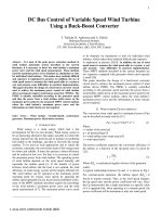
For PMSGs, both surface PM and inset PM pole rotors are used. A typical cylindrical rotor configu-
ration is shown in Figure 10.1. For IPM pole rotors, the magnetic reluctance along the direct (
d) axis is
larger than for the transverse (
q) axis; thus, L
d
< L
q
— that is, inverse saliency, in contrast to electromag-
netically excited pole rotors for standard synchronous machines.
FIGURE 10.1 Four-pole surface permanent magnet (PM) and inset PM pole rotor configurations.
q
N
N
N
N
N
N
N
N
N
N
N
S
S
S
S
S
S
S
S
S
S
S
S
N
N
N
N
S
S
S
S
d
Carbon fiber
mechanical shield
0.5−1 mm copper shield
for superhigh speed rotors
PM piece
-Nonmagnetic fill - for surface PM-poles
-Laminated magnetic fill for inset PM-poles
Magnetic yoke:
-Solid for surface PM-poles
-Laminated for inset PM-poles
N
© 2006 by Taylor & Francis Group, LLC
10-4 Variable Speed Generators
(Figure 10.2) to the stator, in cylindrical rotor configurations. Interior rotors require a carbon fiber
mechanical shield (retainer) against centrifugal forces for high-speed applications (above 50 to 80 m/sec
peripheral speed). In contrast, external rotors do not need such a retainer, but the yoke has to withstand
high centrifugal forces in high-speed rotors.
For high-speed PMSGs with cylindrical rotors, characterized by a wide constant power speed range
(
external diameter and length and the same PM weight. For generators, they provide for small
l
d
= l
q
inductances in per unit (P.U.) terms, which should result in lower voltage regulation.
However, inset PM pole or hybrid rotors, due to inverse saliency (
L
d
< L
q
) may produce zero voltage
regulation at a certain load that is fixed by design. In self-regulated PMSGs, driven at quasi-constant
speed, such a design may prove to be practical.
In super-high-speed PMSGs with fundamental frequency above 1 kHz, the core loss and rotor loss are
major concerns. To reduce rotor losses, the surface PM rotors are the natural choice. In such applications,
copper shields surrounding the PM pole reduce the harmonics losses in the rotor PMs, and, moreover,
solid back iron in the rotor is acceptable. This, in turn, leads to better rotor mechanical integrity.
Disk-shaped PM rotors were also proposed to increase the torque/volume in axial-length constraint
designs. The typical rotor has the PMs embedded in a stainless disk; a mechanically resilient magnetic
The configurations in Figure 10.4 preserve the ideal zero axial force on the central part when the latter
rotor (stator) is in the center position; thus, the bearings are spared large axial forces.
It is, in principle, possible to use only one of the two rotor parts in Figure 10.4b with a single stator
in front of it, axially. But in this case, the axial (attraction) force between rotor and stator is very large,
and the bearings have to handle it. Special measures to reduce vibration and noise are required in this
situation.
FIGURE 10.2 Four-pole cylindrical external rotor.
q
N
N
N
N
N
N
N
N
N
N
N
N
S
S
S
S
S
S
S
S
S
S
S
S
N
N
N
N
S
S
S
S
d
External rotor yoke
PM piece
-Nonmagnetic fill (surface PM-poles)
-Laminated magnetic fill (inset PM-poles)
Interior stator
ωω
max
/
b
The d axis falls along the PM field axis in the airgap. The rotor may be internal (Figure 10.1) or external
> 4
), a hybrid surface PM pole and variable reluctance rotor may be used (Figure 10.3a through
Figure 10.3c). The surface PM pole rotors were proven capable of slightly more torque for given rotor
disk behind the PMs is also feasible, as it reduces the rotor harmonics losses (Figure 10.4a and Figure 10.4b).
© 2006 by Taylor & Francis Group, LLC
Permanent Magnet Synchronous Generator Systems 10-5
FIGURE 10.3 Four-pole permanent magnet (PM) rotor: (a) with surface PM pole, (b) A-A cross-section, and
variable reluctance, (c) B–B cross section.
FIGURE 10.4 Four-pole disk-shape permanent magnet (PM) rotors: (a) interior rotor (with dual stator) and (b)
double-sided rotor (with single and dual face stators).
Shaft
AB
A
PM section
Variable
reluctance
section
B
N
S
A-A
(a)
(b) (c)
q
S
N
d
S
N
S
L
d
= L
q
N
S
N
B-B
q
d
L
q
> L
d
PMs
Stator
N
S
NS
Stainless steel
disk
PMs
N
N
S S
Solid iron
yoke
AlSiMg
frame
PMs
NS
NS
Stator
SN
S
N
(a) (b)
© 2006 by Taylor & Francis Group, LLC
10-6 Variable Speed Generators
and its inertia are small. In contrast, the two external stators will require a magnetic yoke (each of them).
To reduce the stator’s axial length, the number of poles must be increased. This renders the disk rotor
PM generators favorable for a large number of poles (2
p
1
> 6) for fundamental frequency below 2 kHz.
Multiple rotor and stator disk rotor configurations were proposed for low-speed high-torque direct drives
for elevators [5].
Though quite a few thorough comparisons between cylindrical and disk rotor PM synchronous
machines were performed, no clear-cut “prescriptions” are available. However, it seems that depending
on the number of poles (2
p
1
> 8, 10) and if the stack length is short, the disk rotor PM synchronous
generators lead to higher torque/volume for equivalent losses and torque [6, 7].
For large torque (diameter) applications, such as direct-driven wind generators, low-cost ferrite PMs
were proposed to cut the costs [8]. Heavy PM flux concentration is required. A typical such rotor structure
Apparently, the configuration exhibits saliency (
L
d
< L
q
) due to the presence of the PMs along the d
axis field path. In reality, the slim flux bridges (h
b
) lead to their early saturation by the q axis (torque)
currents in the stator; thus, the saliency decreases with load to negligible values. A small machine
inductance generally produces small voltage regulation.
To reduce the tangential fringing flux of the PMs in the airgap,
b
PM
> 3 to 4g (g is the mechanical gap
between rotor and stator). For rotor diameters of 3 to 4 m, even at speeds below 30 rpm, typical for large
wind turbines, a mechanical airgap of at least 5 mm is mechanically required. Therefore, the PM width
b
PM
should be at least 15 to 20 mm, and the pole pitch
τ
should not be less than 80 to 100 mm to provide
smooth PM flux density distribution in the airgap.
The silicon iron laminated poles of the rotor lead to moderate rotor surface and pulsation harmonics
core losses in the rotor.
FIGURE 10.5 Ferrite permanent magnet (PM) rotor with flux concentration.
b
PM
h
b
q
d
Ferrite PMs (low cost)
Laminated poles
Nonmagnetic wedges
Nonmagnetic spider
Holes for fixing
bolts
g(airgap)
N
S
S
N
N
S
S
N
In the interior rotor configuration, there is no rotor magnetic core in Figure 10.4a, and the axial rotor length
is shown in Figure 10.5.
© 2006 by Taylor & Francis Group, LLC
Permanent Magnet Synchronous Generator Systems 10-7
Generally, stators are made of a laminated iron core with slots, but slotless cores may be adopted for
high-speed (frequency) applications. The core may be cylindrical or, again, disk shaped (Figure 10.6a
and Figure 10.6b).
The radial and axial slots are stamped into, respectively, radial and rolled silicon-iron lamination
cores.
In super-high-speed applications, the core losses in the stator teeth may become so large that their
elimination could prove beneficial, despite PM flux density reduction due to increased “magnetic” airgap.
The space left between Gramme-ring coils is required to fix the rolled lamination stator core of the
disk rotor PMSG (Figure 10.7b) to the machine frame. Still, the stator structure is a bit mechanically
fragile, and care must be exercised in its mechanical design to avoid inadmissible axial bending.
The Gramme-ring winding is a special winding with short end connections, but a standard three-
phase winding may be placed, as for the cylindrical rotor machine, in a dummy, isolation-made, slotted
winding holder to reduce manufacturing time and costs.
As expected, being “washed” by the cooling air, the stator slotless windings may be better cooled, but,
due to the larger magnetic airgap, the winding loss and torque tend to be notably larger than that in
slotted cylindrical stator configurations.
FIGURE 10.6 Slotted stator cores: (a) for cylindrical-rotor permanent magnet synchronous generator (PMSG) and
(b) for disk-rotor PMSG.
A.C. winding
Stator uniform
slotting
Radial
lamination core
A.C.
winding
(a)
(b)
Axial slot opening
Rolled lamination
core for disk-rotor
PM-SG
Slotless stators for cylindrical and disk-shaped rotor PMSGs are shown in Figure 10.7a and Figure 10.7b.
© 2006 by Taylor & Francis Group, LLC
10-8 Variable Speed Generators
10.2.1 Distributed vs. Concentrated Windings
Distributed single- or double-layer three-phase windings with q = 2 ÷ 6 are typical for PMSGs. Chording
of coils in a ratio of about 5:6 is performed on double-layer windings to reduce the fifth and seventh
stator magnetomotive force (mmf) space harmonics and their additional rotor surface and PM eddy
current losses.
A large
q (slot/pole/phase) leads to an increase in the order of the first slot harmonic, with amplitude
that is thus reduced along with its additional rotor surface and PM eddy current losses. However, for
large
q, the end connections tend to be large, and thus, the Joule losses tend to increase. Up to q = 3, a
good compromise in terms of total losses may be secured.
Distributed windings are used to provide an almost sinusoidal electromagnetic field (emf) in the stator
winding despite the nonsinusoidal (rather flat) PM flux density distribution in the airgap. Stator or rotor
skewing may be added to further sinusoidalize the emf at the price of a 5 to 7% reduction in emf root
mean squared (RMS)
value for one stator slot pitch skewing. Sinusoidal emf requires sinusoidal shape
current to provide, ideally, rippleless interaction (PM to winding currents) torque.
The rather trapezoidal emf is obtained with three slots per pole (
q = 1). If the PM airgap flux density
distribution is flat in this case, trapezoidal distribution (ideally rectangular) current control is required
to reduce torque pulsations between the commutation of phases. For rectified output PMSGs, the
exploitation of the third harmonic in the emf can lead to increased power conversion; so trapezoidal emf
may be adopted in some designs.
In an effort to reduce stator manufacturing costs and the winding Joule losses, concentrated (non-
overlapping) windings with
q < 1 were adopted [9, 10].
The number of stator slots
N
s
and the number of rotor PM poles 2p
1
are close to each other. The closer
to unity is the ratio N
s
/2p
1
, the better, as the number of periods of fundamental torque at zero current
due to PMs and slot openings is equal to the smallest common multiplier (SCM) of N
s
and 2p
1
. Also,
the equivalent winding factor for the winding is large if the SCM is large.
but they imply longer end connections and, thus, longer stator frames in comparison to double-layer
concentrated windings. The latter allow for a slightly less slot filling factor, as there are two coils in a slot
and, inevitably, some airspace remains between the two coils [10].
FIGURE 10.7 Airgap windings: (a) for cylindrical rotor and (b) for double-sided disk-shaped rotor.
Airgap
winding
Insulation made
winding holder
(a) (b)
Radial lamination
yoke
Gramme-ring
airgap winding
Rolled lamination
stator core
Ring shape
coils
The nonoverlapping coil windings may be built in one layer or two layers (Figure 10.8a through Figure10.8c).
The single-layer concentrated windings (Figure 10.8b) lead to only slightly higher winding factors (Table 10.1),
© 2006 by Taylor & Francis Group, LLC
Permanent Magnet Synchronous Generator Systems 10-9
The winding factor is defined as the ratio of the resulting emf E
cp
per current path (or phase) divided
by the product of the number of coils N
cp
to their emfs E
c
:
(10.1)
Values of k
W
0.866 compare favorably with distributed windings. There are some side effects, such
as the presence of both odd and even harmonics in the stator three-phase mmf. As such, harmonics
count as leakage flux if they lead to an increase in the leakage inductance per current path (or
phase). Some single-layer concentrated windings produce subharmonics that create additional core
losses and further leakage inductance increases. This is not so, in general, for double-layer concen-
trated windings [10].
The cogging torque number of periods is given by the SCM of the N
s
and 2p
1
. Some representative
does not always coincide with the maximum winding factor; thus, a compromise between the two is
required, with the latter being more important. For N
s
/2p
1
= 15/14, 8/9, 12/10, 12/14, 18/16, very good
results are obtained.
FIGURE 10.8 Four-pole winding layouts for permanent magnet synchronous generators (PMSGs): (a) distributed
winding (q
= 1); (b) single-layer concentrated winding; and (c) double-layer concentrated winding.
Overlapping
end connectors
A
C'
B'
C'
A'
B'
B
C
B
C
A
(a)
(b) (c)
A'
Nonoverlapping
end connectors
A
C'
B
A'
C
B'
Nonoverlapping
end connectors
A
A
C'
C
C'
B
B'
B
A'
A'
CB'
k
E
NE
W
cp
cp c
=
⋅
data are given in Table 10.2. As can be seen by comparing Table 10.1 and Table 10.2, the maximum SCM
10-10 Variable Speed Generators
TABLE 10.1 Winding Factors of Concentrated Windings
N
s
Slots
2p — Poles
2 4 6 8 10 12 14 16
* ** * ** * ** * ** * ** * ** * ** * **
3 * 0.86 **************
6 * * 0.866 0.866 * * 0.866 0.866 0.5 0.5 ******
9 * * 0.736 0.617 0.667 0.866 0.960 0.945 0.96 0.945 0.667 0.764 0.218 0.473 0.177 0.175
12 ******0.866 0.866 0.966 0.933 * * 0.966 0.933 0.866 0.866
15 * * * * 0.247 0.481 0.383 0.621 0.866 0.866 0.808 0.906 0.957 0.951 0.957 0.951
18 ******0.473 0.543 0.676 0.647 0.866 0.866 0.844 0.902 0.960 0.931
21 ******0.248 0.468 0.397 0.565 0.622 0.521 0.866 0.866 0.793 0.851
24 ********
0.930 0.463 * * 0.561 0.76 0.866 0.866
Note: * = one layer; ** = two layers.
Source: Adapted from F. Magnussen, and C. Sadarangani, Winding factors and Joule losses of PM machines with concentrated windings, Record of
IEEE–IEMDC-2003, vol. 1, 2003, pp. 333–339.
© 2006 by Taylor & Francis Group, LLC
© 2006 by Taylor & Francis Group, LLC
Permanent Magnet Synchronous Generator Systems 10-11
A large SCM means that, in general, low cogging (zero current) torque is obtained without skewing.
A few percent (5 to 7%) output is saved this way.
As the number of poles 2p
1
is increased, with N
s
≈ 2p
1
, both the winding factor and the SCM increase,
securing good performance. This means that for some low-speed applications, concentrated windings
are definitely favorable.
By adequate rotor geometry, the emf may be made quasi-sinusoidal, and thus, vector and direct
torque control are feasible. However, when the airgap has to increase due to mechanical reasons (higher
diameter, etc.), the tangential fringing flux of the PMs tends to increase, reducing the emf. Poor
utilization of PMs takes place, and reduced output is the result. When the slots are thin (in small
torque machines), there may not be enough mmf per slot to secure high torque density. With these
limitations in mind, concentrated windings may represent a practical solution to high-performance
PMSGs in various applications.
distributed winding by making adequate connections of coils.
Note that so far, we considered the stator cores as being made of single, stamped laminations. For
outer stator diameter above 1 m, the stator core has to be made from a few sections, as is usually the
additional losses, torque pulsations, vibration, and noise.
10.3 Airgap Field Distribution, emf and Torque
The airgap field in PMSGs has two main sources: the PMs and the stator mmf.
The presence of slot openings and magnetic saturation, together with the rotor PM geometry, makes
the computation of airgap field in PMSG a complex problem, solvable as it is only by two-dimensional
(2D) or three-dimensional (3D) finite element method (FEM).
However, at least for surface PM pole rotors, the influence of magnetic saturation may be neglected
unless very high current loading is allowed for, in very high torque density designs. Once magnetic
saturation is neglected, the superposition of PM and stator mmf fields in the airgap is acceptable.
Moreover, the effect of stator slot openings on airgap field distribution may be added by introducing
a P.U. (relative) airgap performance function
λ
(
θ
), variable with angular position along the stator surface
stator mmf produced airgap field distribution in the slotless machine, and then the slot opening effect
can be introduced by multiplication with
λ
P. U .
(
θ
):
(10.2)
TABLE 10.2 Smallest Common Multiplier (SCM) of N
s
and 2p
1
N
s
2p
1
246810121416
3 612******
6 *12*2430* * *
9 * 36 18 72 90 36 126 144
12 * * * 24 60 * 84 48
15 * * 30 120 30 60 210 240
18 * * * 72 90 36 126 144
21 * * * 168 210 84 42 336
24 ****120*16848
BB
PM mmf PM mmf
slottless
PU,,
() ( ) ()
θθθλθ
=−⋅
1
The Gramme-ring windings in Figure 10.7 may be assimilated to a single-layer concentrated or
(Figure 10.9). Consequently, a 2D analytical field model may be used to calculate separately the PM and
case with SGs (Chapter 5). Modular stator cores are plagued with noncircularity eccentricities that create
© 2006 by Taylor & Francis Group, LLC
10-12 Variable Speed Generators
where
θ
1
is the rotor displacement, and
θ
and
θ
1
are taken in electrical degrees or radians. Complete 2D
analytical models could be built for the unsaturated PMSG with surface PM pole cylindrical rotors.
For the axial airgap (disk-shaped rotors), a similar 2D theory in the axial (z) and in polar coordinates
(
θ
1
,
θ
) may be developed, while the variation of variables in the radial direction, r, is handled by an
additional P.U. coefficient
λ
p.u.
(r). A quasi-3D analytical model is thus obtained. A complete 2D analytical
model for a cylindrical rotor is introduced in Reference [11] and pursued further in Reference [12] for
cogging torque and emf computation. For the disk-shaped rotor case, a quasi-3D complete analytical
model is introduced in References 13 and 14 with emf and cogging torque thoroughly documented. In
both cases, the PM equivalent mmf and the stator mmf distributions are decomposed in Fourier space
harmonics, and superposition is applied afterward.
As these analytical models are fairly general, and could handle both distributed and concentrated stator
windings, we will treat these here in some detail in view of their potential application to design optimi-
zation attempts.
The equivalent circuit for phase a in stator coordinates is shown in Figure 10.10. Core losses are
neglected. represents the PM-induced voltage (emf) in phase a which, evidently, is a bipolar motion-
induced voltage that varies with the rotor position:
(10.3)
FIGURE 10.9 Position angles with rotor in motion.
FIGURE 10.10 Steady-state phase equivalent circuit.
θ (angular position
on rotor surface)
Rotor
displacement
Position reference
to the rotor
N
S
θ
1
θ
2
N
N
S
N
S
S
E
PM
a
EWBlu
PM c PMi stack
i
N
a
s
=⋅⋅⋅
=
∑
1
3
E
PMa
E
aa
E
ab
E
ac
E
a
= E
PMa
+ E
aa
+ E
ab
+ E
ac
R
R - phase resistance
L
sl
- leakage inductance
jωL
sl
V
a
i
a
© 2006 by Taylor & Francis Group, LLC
Permanent Magnet Synchronous Generator Systems 10-13
where
l
stack
is the stack
u is the peripheral speed
B
PMi
is the PM average flux density at slot i of phase a
W
c
is the number of turns per coil
N
s
is the stator slots
E
aa
, E
ab
, and E
ac
are the self-induced and mutual-motion-induced voltages in phase a. They are produced
by the stator currents:
(10.4)
where is the average instantaneous magnetic flux density produced by coil i of phase a at slot j of the
same phase a. are the average instantaneous magnetic flux densities produced by coil i of phase
b(c) at slot j of phase a. That is, mutual stator emfs vary with rotor position if inset or interior
(or variable reluctance) rotor poles exist.
operated:
• PM magnetization harmonics
• Current sheet distribution of a coil
• Stator slot openings
(10.5)
where
α
p
=
τ
m
/
τ
is the magnet/pole pitch ratio
p
1
is the pole pairs
B
r
is the remnant flux density of the PMs
θ
2
=
θ − θ
1
The stator current sheet produced by a coil (Figure 10.11b) may also be approximated in Fourier
series:
(10.6)
EWBlu
aa c cij
a
stack
j
N
i
N
cs
=⋅⋅⋅
==
∑∑
11
3/
EEWBlu
ab c bij
a
stack
j
N
i
N
cs
=⋅⋅⋅
==
∑
11
3/
∑∑
∑
=⋅⋅⋅
==
EWBlu
ac c cij
a
stack
j
N
i
N
cs
11
/33
∑
B
aij
a
BB
bij
a
cij
a
,
EEE
aa ab ac
,,
M
B
n
n
r
p
n
p
p
()
sin( )
co
,,
θ
µ
α
πα
πα
2
0
135
2
2
2
=⋅⋅
=
∞
∑
/
/
ssnp
12
θ
I
Wi
wn
nw
R
n
c
s
s
s
c
n
() sin cos( ( ))
θ
π
θτ
=⋅⋅⋅−
=
4
1
2
2
1
/
∞∞
∑
When considering the following, the approximations in Figure 10.11a through Figure 10.11d are
The rectangular PM magnetization (Figure 10.10) may be decomposed in Fourier series:
© 2006 by Taylor & Francis Group, LLC
10-14 Variable Speed Generators
where
i is the instantaneous current in the coil
w
s
is the slot opening
R
s
is the interior stator radius
τ
c
is the coil span angle
The relative airgap permeance (Figure 10.11c)
λ
P. U .
(
θ
) may be determined by considering semicircular
flux paths in the slots with radii equal to the shortest distance to tooth edges:
(10.7)
Away from slot openings,
λ
p.u.
is unity and, in front of slot openings, has a variable subunity value,
dependent on w
1
, which is the distance to the closest slot edge. For semiclosed slots, w
s
refers to the slot
opening of the airgap and not to the actual slot width, and thus, the airgap permeance pulsations with
θ
are notably smaller, as expected.
FIGURE 10.11 (a) Permanent magnet (PM) magnetization, (b) current sheet, (c) slot flux line ideal distributions,
and (d)
λ
P.U.(
θ
).
B
r
θ
2
S
t
m
(a)
(c)
(b)
(d)
N
S
N
S
N
W
s
1
θ
λ
p.u.
(θ)
τ
coil
×
×
2π
J =
iW
e
w
s
θ
W
s
W
1
R
s
R
r
R
m
W
2
W
1
W
2
g
λθ
θ
µ
µ
π
pu
l
l
g
gw
m
r
m
r
()
()
=
+
++
2
1
© 2006 by Taylor & Francis Group, LLC
Permanent Magnet Synchronous Generator Systems 10-15
Making use of Equation 10.2, the expressions of are obtained with
Equation 10.5 and Equation 10.6 and the 2D field model [11]:
(10.8)
where µ
r
is the P.U. value of PM permeability: 1.03 to 1.08. For np
1
= 1, Equation 10.8 has a zero
denominator and should be changed to the following [11]:
(10.9)
For the interior rotor,
(10.10)
while for the exterior rotor,
(10.11)
Consequently, Equation 10.8 and Equation 10.9 have to be modified, as now R
s
< R
r
< R
m
:
(10.12)
The above expressions account for the rotor curvature and should be particularly instrumental for low
rotor diameter (low torque) PMSGs.
BandB
PM
slotless
mmf
slotless
() ()
θθ θθ
−−
11
B
B
PM
slotless
r
r
n
n
p
()
sin
,,
θθ
µ
π
πα
−= ⋅⋅
=
∞
∑
1
135
2
4
αα
p
R
R
np
p
np
np np
r
m
⋅
−
⋅
−+
(
)
−+
+
1
1
2
1
1
1
1
12 1
1
()
() ()
⋅⋅
(
)
⋅−
(
)
−
+−
R
R
np
R
R
np
r
m
r
r
r
s
r
2
1
2
1
1
1
1
µ
µ
µ
µ
rr
m
s
r
m
R
R
np
R
R
np
(
)
−
(
)
22
11
⋅⋅
⋅
+
−+
r
R
R
R
R
r
s
np
m
s
np
m
11
11
−≠
+np
np p
1
1
11 1
1cos ( )
θθ
for
B
B
n
p
np
PM
slotless
r
r
n
p
p
()
sin
(
θθ
µπα
πα
−= ⋅⋅ ⋅
1
21
2
11
2
135
1)
,,
−
=
∞
∑
n
⋅⋅
()
−
()
+
R
R
R
R
R
R
R
R
m
s
r
s
r
s
m
r
22
2
ln
+
−
⋅−
−
2
1
2
1
1
µ
µ
µ
µ
r
r
r
s
r
r
m
s
R
R
R
R
(()
−
()
22
R
R
r
m
⋅+
−1
1
R
r
s
cos( )
θθ
RRgRRgh
ms rs m
=− =−−;
RRgRRgh
ms rs m
=+ =++;
B
B
p
np
PM
slotless
r
r
n
p
p
()
sin
(
θθ
µπα
πα
−=− ⋅⋅ ⋅
1
21
4
11
2
135
1)
,,
−
⋅
=
∞
∑
n
⋅
−
()
+
()
−+
−
() ()np np
R
R
np
R
R
np
m
r
m
r
r
1
21
1
12 1
11
µ
++−
⋅−
()
−
()
−
1
2
1
2
1
11
µ
µ
µ
r
s
r
r
r
s
m
R
R
np
R
R
np
R
mm
r
R
np
()
2
1
⋅
+
−
r
R
R
R
m
np
s
m
1
1
⋅
−+np
s
r
np
R
R
np
11
11
1
cos (()
θθ
−≠
11
1for np
© 2006 by Taylor & Francis Group, LLC
10-16 Variable Speed Generators
The armature reaction flux density in the airgap, produced by a single stator coil with its sides placed
in slots k and l, is as follows [12]:
(10.13)
For external rotors, a similar formula could be obtained with instead of instead of and
instead of
Ultimately, both PM and mmf airgap flux density expressions in Equation 10.9 and Equation 10.10
have to be multiplied by the P.U. airgap permeance function
λ
p.u.
(
θ
) of Equation 10.7 with the contri-
butions of all coils for each phase added up (Equation 10.3 and Equation 10.4).
Denoting by E
a
, E
b
, and E
c
the total emf per phases a, b, and c, the electromagnetic torque T
e
is, simply,
(10.14)
The instantaneous electromagnetic torque includes the interaction torque between the PM flux and stator
current and the so-called reluctance (no PM) torque.
The torque at zero current (cogging torque) is not, however, included in Equation 10.14. The cogging
torque is, in fact, produced by the tangential forces on the slot walls:
(10.15)
and ssg = 0 outside the slot opening; and ssg = 1 on the left side of the slot opening;
and , and ssg = −1 on the right side of the slot opening.
Typical results that compare PM, mmf airgap flux densities, cogging, and total torque obtained from the
model looks adequate to describe airgap flux density pulsations due to slot openings both for the PM and
armature contributions. Also, it correctly portrays the cogging torque and the total torque variation with
rotor position (or with time). Any shape of current waveform can be dealt with through its time harmonics.
The model, however, ignores magnetic saturation and cannot directly handle inset or interior PM
rotor configurations.
As already alluded to, a similar quasi-3D analytical model was developed for disk-shaped (axial flux)
PM rotor configurations [13, 14].
The 2D analytical model for the axial airgap machine is developed in the axial circumferential coordinates
1
(10.16)
with R
ai
and R
ae
the inner and outer PM radii, and
(10.17)
with
α
and
β
as correction coefficients. By making the computations for 15 to 20 values of the radius
and averaging them, while taking into account that the pole pitch
τ
and the PM span
τ
m
vary with radius
r, similar results may be obtained.
The emf and cogging torque waveforms obtained through such a model [14] are compared with 3D
B
Wi
r
n
n
kl
c
w
R
w
R
n
s
s
s
s
()
sin
θ
µ
π
≅⋅⋅
(
)
(
)
⋅
=
∞
∑
2
1
0
2
2
1
ssin
n
r
R
c
s
n
τ
2
/⋅
+
()
−
()
⋅−
1
1
2
2
R
r
n
R
R
n
coil
r
r
s
ncos( (
θτ
22))
R
r
s r
R
sr
r
R
,
R
r
r
R
R
s
r
R
R
r
s
.
T
Ei Ei Ei
pp
U
R
p
e
aa bb cc
m
=
++
⋅=⋅≈⋅
()
ω
ω
1
11 1 1
; Ω
r
T
lR
N
B
m
N
cog
stack s
s
PM
s
() (
θ
π
µ
π
θ
≅⋅ +
⋅
2
2
0
2
1
RR g ssg
m
m
N
s
+
=
∑
α
)
1
g
α
= 0 gwg
α
=+
1
g
α
=+wg
2
gr r R a r R a
ai ae
( ) [tan(( ) ) tan (( ) )]=−−−
−
1
1
π
//
aRR
ae ai
=−
αβπ
()tan()//2
analytical model and from 2D FEM are shown in Figure 10.12a through Figure 10.12d [12]. The 2D analytical
(z,
θ
−
θ
), while the correction for the radial direction is handled [13] as follows (Figure 10.13a and Figure 10.13b)
FEM results (Figure 10.14a and Figure 10.14b). There is some 11% difference between analytical and 3D
© 2006 by Taylor & Francis Group, LLC
Permanent Magnet Synchronous Generator Systems 10-17
FIGURE 10.12 Analytical vs. finite element method (FEM) airgap flux density distributions and torques for sinu-
soidal current: (a) permanent magnet (PM) flux density, (b) armature flux density, (c) cogging torque, and (d) total
torque.
FIGURE 10.13 Disk-rotor permanent magnet synchronous generator (PMSG) model: (a) two-dimensional geom-
etry (z,
θ
−
θ
1
) and (b) radial (third) dimension r.
FEA
ws = 0.0019 Rm = 0.026 g = 0.0006 lm = 0.003 magnet pitch/pol pitch = 0.967
0
1
0.8
0.6
0.4
0.2
0
−0.2
−0.4
−0.6
−0.8
−1
20
Field density in tesla
40 60
Position in degrees
(a)
(c)
(b)
(d)
80 100 120
FEA
0
4
3.5
3
2.5
2
1.5
1
0.5
0
50
Torque in Nm
100 150 200
Angle in degrees
250 350 300
Analytical
FEA
0
0.8
0.6
0.4
0.2
0
−0.2
−0.4
−0.6
−0.8
2 4
Cogging torque in Nm
6 8 10 12
Angle in degrees
14 16 20 18
Analytical
FEA
0
0.015
0.01
0.005
0
−0.005
−0.01
−0.015
−0.02
−0.025
−0.03
50 100
Armature field of a coil (T)
150 200
Angle in degrees
250 300 350 400
ws = 0.0026 Rm = 0.016 g = 0.00095 lm = 0.003 coil angle = 60
Analytical
Analytical
z
S
t
m
t
Solid rotor disk
(a) (b)
(θ–θ
1
)
N
PMs
S
r
R
ai
R
ae
NA
© 2006 by Taylor & Francis Group, LLC
10-18 Variable Speed Generators
FEM results, probably due to the fringing flux through stator slot necks which is neglected. Unfortunately,
this fringing (leakage) PM flux may be calculated only through FEM. FEM-based corrections for fringing
are possible in an iterative way or through applying a fudge factor from experiments. The same assertion
should hold for the cylindrical rotor analytical model. The situation is delicate, especially with small slot
openings.
Note that while a complete 2D (3D) analytical field model was developed for both cylindrical and
disk-shaped rotors, its Fourier series nature makes it useful for design optimization (Figure 10.14a and
Figure 10.14b). It is still a bit too complicated for preliminary design, when a more simplified circuit
model with analytically defined parameters is required. Finally, the 2D (3D) FEM may be used for model
design optimization.
But before dealing with the circuit model, let us explore first cogging torque details and core loss
modeling, as they make use of FEM, also, in advanced representations.
FIGURE 10.14 Disk-shaped rotor permanent magnet synchronous generator (PMSG) by three-dimensional ana-
lytical vs. three-dimensional finite element method models: (a) electromagnetic field (emf) waveforms and (b)
cogging torque.
3D FEM
0
300
200
100
0
−100
−200
−300
30
Induced voltage (V)
60 90 120 150 180 210
Electrical angle (deg)
(a)
(b)
240 270
360
300 330
Analytical with leakage
fluxes
Analytical without leakage fluxes
3D FEM
6
6
4
2
0
−2
−4
−6
12
Cogging torque (p.u.)
18 24 30 36 42 48 54
Electrical angle (deg)
60 66
96
72 78 84 90
Analytical
© 2006 by Taylor & Francis Group, LLC
Permanent Magnet Synchronous Generator Systems 10-19
10.4 Stator Core Loss Modeling
There are two ways to approach the complex problem of stator core losses in PMSGs. The first approach
starts with a simplified flux distribution and a simplified core loss formula and eventually advances to
using FEM for refinements.
In the second approach, FEM distribution of flux density evolution with time is considered in each
core volume element, which gives stator current/time waveforms. Then, the hysteresis and eddy current
losses are added up to obtain the total core losses by again using some simplified core loss formulas.
Recent research efforts showed that not only is the flux density not sinusoidal in time at a point in a
stator core, but also its vector direction changes in time at that point, more in the yoke and less in the
teeth. This way, the traveling component of flux density time variation was proven to be important in
computing the core loss. The data from AC magnetization (from Epstein probe) have to be corrected
with the eddy current losses due to rotation. The presence of slot openings and the distribution of
windings in slots lead to time harmonics in the stator core flux density, even for distributed windings
and sinusoidal currents at constant speed. Also, the on-load core losses tend to differ from no-load core
losses; thus, the simplified core loss standard formulas [3, 5] may be used only in very preliminary design
stages. The presence of slot openings and the distribution of windings in slots lead to time harmonics
in the stator core flux density, even for distributed windings and sinusoidal currents at constant speed.
Finally, the importance of “rotation” on core loss tends to increase for concentrated windings in com-
parison with distributed windings.
All of these aspects tend to suggest that a realistic approach should start first with FEM core loss
estimates, and then their curve fitting to even more simplified formula may be operated, for design
optimization tasks.
10.4.1 FEM-Derived Core Loss Formulas
It has been known for a long time that the combined alternative and traveling fields produce more core
losses than alternating fields of the same frequency and amplitude. The quantization of this phenomenon
has not been, in general, taken into consideration.
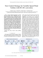
FEM has brought in a possibility to account for rotational field losses in core losses of brushless
density has traveling field components of various values, depending on their locations in the stator teeth
and yoke. Further on, at some points, the situation is different for given points for concentrated windings
It is evident that the short/long axis ratio c of the elliptical variation of B
r
/B
o
for each harmonic is
different for distributed and concentrated windings (Figure 10.15a through Figure 10.15d, and
Figure 10.16a and Figure 10.16b).
For the distributed winding, the traveling field components (c > 0.3) are notable at the teeth bottom
and in part of the yoke, while for concentrated winding, they also show up near the teeth top and
throughout the yoke. Larger core losses are expected for concentrated windings. A general FEM-derived
formula for total stator core losses is of the following form [15]:
(10.18)
where
j is the order of the flux density time harmonic
i is the finite element number
g
i
is the mass of i finite element
f is the frequency
γ
is a correcting constant
c is the short-to-long axis ratio of field vector hodograph in element i for the harmonic j
Pg
jf
B
jf
Fe total i h mji eddy−
=
+
εε
α
100 100
⋅+
=
∑
2
1
1Bc
mji ij
i
m
α
γ
()
=
∑
j
n
1
machines (Figure 10.15a through Figure 10.15e) [15]. In different points, such as a, b, c, d, e, the flux
(Figure 10.16a and Figure 10.16b) [15].
© 2006 by Taylor & Francis Group, LLC
10-20 Variable Speed Generators
FIGURE 10.15 Distributed winding interior permanent magnet synchronous generator (IPM-SG) core flux density:
(a) the points a, b, c, d, and e, (b) flux density vector hodograph in point a, (c) elliptical variation for each harmonic,
(d) short to long axis c coefficient, and (e) harmonics spectrum of flux density.
Stator
PM
Rotor
Slot
(a)
(b)
(c)
(d)
(e)
d
c
a
b
e
Bt
B(T)
Br
Fundamental
0
1
1
0−1
−1
−1
Time t
0
1
c = 0.533
Br(T)
Br(T)
0
0
1
1.5
1.5
0
0
0.1
−1
−0.1
−1.5
−1.5
Bt(T)
Bt(T)
Distributed winding IPMSM
point a
Order of harmonics
1
0.8
0.6
0.4
0.2
0
1 3 5 7 9 11 13 15
Flux dens. B(T)
© 2006 by Taylor & Francis Group, LLC
Permanent Magnet Synchronous Generator Systems 10-21
In case stator current time harmonics are considered, the same formula is applied for each current
harmonic frequency.
Comparison between experimental losses and calculated ones by conventional (analytical) models
and Equation 10.18 — for the distributed and concentrated windings — are shown in Figure 10.17
The increase in precision by considering traveling field components is evident.
sinusoidal current.
FIGURE 10.16 Concentrated winding interior permanent magnet synchronous generator (IPM-SG): (a) cross-
section and (b) distribution of short to long axis rate c.
FIGURE 10.17 Core loss evaluation for distributed winding with load.
PM
Stator
(a)
(b)
Slot
Conv. method
20
15
10
5
0
1000
Iron loss (W)
2000 3000
4000
c
= 0
c ≠ 0
Exp.
Speed N (min
−1
)
Distributed winding IPMSM
I = 4A, b = 20°
and Figure 10.18 [15].
Also, the contribution of harmonics in core losses is shown in Figure 10.19 and Figure 10.20 for
© 2006 by Taylor & Francis Group, LLC
10-22 Variable Speed Generators
As expected, the third flux density harmonic is responsible for about 25% of core loss for the concen-
trated winding. Extending the use of concentrated windings at high speed should be done with care, as
core losses tend to be larger than those for distributed windings.
Alternatively, by adding the core loss of radial and tangential flux density time variations in each finite
element for N samples in a time period and over all finite mass elements and separately for eddy currents
and hysteresis losses, another total core loss formula may be obtained [16]:
(10.19)
where
∆t is the sampling time (there are N sampling times in one period T )
are the radial and tangential instantaneous flux density components in element i
are the amplitudes of radial and axial flux densities in element i for the hysteresis cycle j
k
e
, k
h
are experimental constants from the Epstein frame obtained from the slope and intercept
variation of core losses/frequency vs. frequency straight line
Equation 10.19 may also be applied for the computation of rotor core losses.
FIGURE 10.18 Core loss evaluation for concentrated windings with load.
FIGURE 10.19 Flux density harmonics contributions to core losses (distributed winding).
Conv. method
25
15
20
10
5
0
1000
Iron loss (W)
2000 3000 4000
c = 0
c ≠ 0
Exp.
Speed N (min
−1
)
Concentrated winding IPMSM
I = 4A, b = 10°
P
g
N
k
BB
t
BB
Fe total
i
e
r
k
r
kk
−
++
=
−
+
−
1
2
1
∆
θ θθ
k
k
N
i
m
t∆
==
∑∑
2
11
+⋅⋅
()
+
=
∑
g
T
K
BB
ih
mr
ij
j
N
m
ij
pr
i
2
2
1
θ
(()
==
∑∑
2
11 j
N
i
m
p
i
θ
BB
r
kk
,
θ
BB
mr
ij
m
ij
,
θ
Eddy loss
14
10
12
4
6
8
2
0
135791113151719
Iron loss (W)
Hys. loss
Order of harmonics
Distributed winding IPMSM
4000 min
−1
,
I = 4A, b = 20°
© 2006 by Taylor & Francis Group, LLC
Permanent Magnet Synchronous Generator Systems 10-23
The FEM-derived formulas account for actual flux density evolution in all parts of the magnetic circuit,
either for no-load or for on-load conditions. Also, the case of rectangular or sinusoidal current waveforms
may be treated with the same method.
Finally, IPM or surface PM rotors can be accommodated by simplified formulas.
10.4.2 Simplified Analytical Core Loss Formulas
Analytical core loss formulas for stator core loss in PMSGs were derived first for distributed windings
and sinusoidal currents. It was implicit that the flux density varies sinusoidally in time in both stator
teeth and yoke, and also, that their value is the same in all points of the core. Both these approximations
are coarse, as seen in the previous paragraph. The no-load core losses were evaluated first. A simple
formula that even ignores the hysteresis losses is as follows:
(10.20)
is the peak flux density in the airgap. As this formula cannot discriminate between lightly saturated
or heavily saturated teeth and yoke designs, it is somewhat surprising that it is still mentioned in the
literature today [5]. But as long as the core losses are notably smaller than copper losses, notable errors
in the former do not produce design disasters. This is not so in optimized designs, where winding and
nonwinding losses tend to be of about the same value, or in high-speed PMSGs.
For q = 1 distributed windings and rectangular current, the PM airgap flux density distribution
load [3]. The total eddy current loss formula at no load for such cases is of the following form:
(10.21)
where
R is the rotor radius
w
t
is the tooth width
w
s
is the slot width
hys is the stator yoke radial thickness
p
1
is the pole pairs
ω
is the electrical fundamental frequency
is the peak flux density in the airgap
FIGURE 10.20 Core loss harmonics breakdown for concentrated winding.
Eddy loss
14
10
12
4
6
8
2
0
1
3 5 7 9 11 13 15 17 19
Iron loss (W)
Hys. loss
Order of harmonics
Concentrated winding IPMSM
4000 min
−1
,
I = 4A, b = 10°
Pkg k B
Fe e
g
/.≈⋅⋅⋅28
2
2
ω
B
g
2
Pkg
R
p
k
ww
w
R
phys
eddy e
ts
t
/ =
+
+
⋅
4
2
1
2
2
32
π
ω
α
()
B
g
2
B
g
2
produces different, linear, flux density variations in the stator teeth and in the yoke (Figure 10.21) at no
© 2006 by Taylor & Francis Group, LLC
10-24 Variable Speed Generators
A rough approximation of Equation 10.21 is as follows [16]:
(10.22)
Equation 10.20 and Equation 10.22 show that the rectangular airgap flux density in the airgap is char-
acterized by notably larger core loss than a sinusoidal one. Consequently, when core loss becomes
important, sinusoidal airgap flux density distribution should be targeted. In the above analytical expres-
sions, the armature reaction field was not considered. In heavily loaded and, especially in IPM rotors,
such an approximation is hardly practical.
Also, it is to be noted that eddy current core losses depend on the flux density waveform (or its variation
velocity). The hysteresis core losses depend essentially only on the peak values of flux density. This is
how simplified analytical formulas for eddy current and hysteresis core loss for rectangular flux density
variation in time and IPM-SG on load were derived [17]:
(10.23)
(10.24)
(10.25)
FIGURE 10.21 Ideal teeth and yoke flux densities variation with rotor position for rectangular airgap flux density.
B
g
B
tooth
B
yoke
2α
2α - PM span angle
β - stator tooth width angle
2β/ω
2α/ω
θ
θ
ωt
PkB
eddy e
g
≈⋅ ⋅ ⋅
6
2
2
ω
PP P
eddy etooth eyoke
=+
Pkg
k
T
dB
dt
dt k
p
eteeth
et
T
e
/ ≈
=
⋅
∫
2
0
2
1
2
ω
πβ
(BBBB B
B
gm dm
d
t
q
t
+− +
+
cos ) sin
αα
2
2
2
dd
tt
q
tt
B
22
2
2
2
2
αα αα
−
+
+
sin sin
Pkg
kR
phys
pB B
eyoke
es
gm dm
/ ≈
⋅
+
π
ω
α
1
2
1
2( ))
sin
s
2
2
1
1
2
1
2
2
2
++
−
Bp
p
B
p
d
q
α
α
α
+
iin sin
()sin
2
2
4
11 1
pp p
BBBp
gm dm
d
αδ α
++
−+
11
α
© 2006 by Taylor & Francis Group, LLC
Permanent Magnet Synchronous Generator Systems 10-25
where
is the PM airgap flux density
is the peak airgap flux density at the rotor surface
is the peak airgap flux density due to d axis current
is the peak airgap flux density due to q axis current
is the pole magnet mechanical angle
is the slot pitch mechanical angle
is the stator interior radius
Finally, the hysteresis losses are expressed by the usual formula:
(10.26)
Though expressions such as Equation 10.24 through Equation 10.26 tend to account for the load
(armature reaction) influence on core losses, they still cannot discriminate directly between designs with
various teeth thickness (geometry) or local magnetic saturation effects. However, as shown in Figure
10.22 [17], the load has a strong influence on stator core losses. In terms of core losses, FEM verifications
at the design stage are highly recommended for critical operation modes. Experiments should follow
whenever possible.
Note that it was suggested that core losses be represented in the circuit model of PMSG by an equivalent
resistance R
c
of the following form:
(10.27)
E
total
is the total emf in the d–q model of PMSG. The term
ω
1
accounts for the hysteresis loss linear
variation with frequency. E
total
is also proportional to frequency. Eddy current core losses are proportional
to frequency squared. Such formulas should also be used with care, as, in fact, R
eddy
and r
hys
vary in turn
with load conditions, and so forth.
FIGURE 10.22 Core loss vs. load at 2500 rpm for a four-pole three-phase 600 W interior permanent magnet (IPM)
synchronous machine.
B
gm
B
dm
B
d
B
q
α
ααβ
t
p=−
1
2()
β
R
s
Pkgk B
hh
ty
ty,
,
/ =⋅⋅
ω
1
2
R
E
P
c
r
Fe
eddy hys
total
total
=
+
=
⋅
1
11
2
3
2
1
R
ω
0
25
30
20
15
10
Core loss (W)
10 20 30 40 50
Experiment
Calculation
60
100
70 80 90
Load (%)