ASTM a370 2020
Bạn đang xem bản rút gọn của tài liệu. Xem và tải ngay bản đầy đủ của tài liệu tại đây (327.79 KB, 13 trang )
This international standard was developed in accordance with internationally recognized principles on standardization established in the Decision on Principles for the
Development of International Standards, Guides and Recommendations issued by the World Trade Organization Technical Barriers to Trade (TBT) Committee.
Designation: A370 − 20
Standard Test Methods and Definitions for
Mechanical Testing of Steel Products1
This standard is issued under the fixed designation A370; the number immediately following the designation indicates the year of
original adoption or, in the case of revision, the year of last revision. A number in parentheses indicates the year of last reapproval. A
superscript epsilon (´) indicates an editorial change since the last revision or reapproval.
This standard has been approved for use by agencies of the U.S. Department of Defense.
1. Scope*
Procedure for Use and Control of Heat-cycle Simulation
1.1 These test methods2 cover procedures and definitions
for the mechanical testing of steels, stainless steels, and related
alloys. The various mechanical tests herein described are used
to determine properties required in the product specifications.
Variations in testing methods are to be avoided, and standard
methods of testing are to be followed to obtain reproducible
and comparable results. In those cases in which the testing
requirements for certain products are unique or at variance with
these general procedures, the product specification testing
requirements shall control.
1.2 The following mechanical tests are described:
Tension
Bend
Hardness
Brinell
Rockwell
Portable
Impact
Keywords
Sections
7 to 14
15
16
17
18
19
20 to 30
32
1.3 Annexes covering details peculiar to certain products
are appended to these test methods as follows:
Bar Products
Tubular Products
Fasteners
Round Wire Products
Significance of Notched-Bar Impact Testing
Converting Percentage Elongation of Round Specimens to
Equivalents for Flat Specimens
Testing Multi-Wire Strand
Rounding of Test Data
Methods for Testing Steel Reinforcing Bars
Annex
Annex A1
Annex A2
Annex A3
Annex A4
Annex A5
Annex A6
Annex A7
Annex A8
Annex A9
1
These test methods and definitions are under the jurisdiction of ASTM
Committee A01 on Steel, Stainless Steel and Related Alloys and are the direct
responsibility of Subcommittee A01.13 on Mechanical and Chemical Testing and
Processing Methods of Steel Products and Processes.
Current edition approved Aug. 1, 2020. Published September 2020. Originally
approved in 1953. Last previous edition approved in 2019 as A370 – 19ε1. DOI:
10.1520/A0370-20
2
For ASME Boiler and Pressure Vessel Code applications see related Specification SA-370 in Section II of that Code.
Annex A10
1.4 The values stated in inch-pound units are to be regarded
as standard. The values given in parentheses are mathematical
conversions to SI units that are provided for information only
and are not considered standard.
1.5 When these test methods are referenced in a metric
product specification, the yield and tensile values may be
determined in inch-pound (ksi) units then converted into SI
(MPa) units. The elongation determined in inch-pound gauge
lengths of 2 or 8 in. may be reported in SI unit gauge lengths
of 50 or 200 mm, respectively, as applicable. Conversely, when
these test methods are referenced in an inch-pound product
specification, the yield and tensile values may be determined in
SI units then converted into inch-pound units. The elongation
determined in SI unit gauge lengths of 50 or 200 mm may be
reported in inch-pound gauge lengths of 2 or 8 in., respectively,
as applicable.
1.5.1 The specimen used to determine the original units
must conform to the applicable tolerances of the original unit
system given in the dimension table not that of the converted
tolerance dimensions.
NOTE 1—This is due to the specimen SI dimensions and tolerances
being hard conversions when this is not a dual standard. The user is
directed to Test Methods A1058 if the tests are required in SI units.
1.6 Attention is directed to ISO/IEC 17025 when there may
be a need for information on criteria for evaluation of testing
laboratories.
1.7 This standard does not purport to address all of the
safety concerns, if any, associated with its use. It is the
responsibility of the user of this standard to establish appropriate safety, health, and environmental practices and determine the applicability of regulatory limitations prior to use.
1.8 This international standard was developed in accordance with internationally recognized principles on standardization established in the Decision on Principles for the
Development of International Standards, Guides and Recommendations issued by the World Trade Organization Technical
Barriers to Trade (TBT) Committee.
*A Summary of Changes section appears at the end of this standard
Copyright © ASTM International, 100 Barr Harbor Drive, PO Box C700, West Conshohocken, PA 19428-2959. United States
Copyright by ASTM Int'l (all rights reserved); Fri Sep 25 07:43:46 EDT 2020
1
Downloaded/printed by
University of Michigan (University of Michigan) pursuant to License Agreement. No further reproductions authorized.
A370 − 20
2. Referenced Documents
3
2.1 ASTM Standards:
A623 Specification for Tin Mill Products, General Requirements
A623M Specification for Tin Mill Products, General Requirements [Metric]
A833 Test Method for Indentation Hardness of Metallic
Materials by Comparison Hardness Testers
A941 Terminology Relating to Steel, Stainless Steel, Related
Alloys, and Ferroalloys
A956/A956M Test Method for Leeb Hardness Testing of
Steel Products
A1038 Test Method for Portable Hardness Testing by the
Ultrasonic Contact Impedance Method
A1058 Test Methods for Mechanical Testing of Steel
Products—Metric
A1061/A1061M Test Methods for Testing Multi-Wire Steel
Prestressing Strand
E4 Practices for Force Verification of Testing Machines
E6 Terminology Relating to Methods of Mechanical Testing
E8/E8M Test Methods for Tension Testing of Metallic Materials
E10 Test Method for Brinell Hardness of Metallic Materials
E18 Test Methods for Rockwell Hardness of Metallic Materials
E23 Test Methods for Notched Bar Impact Testing of Metallic Materials
E29 Practice for Using Significant Digits in Test Data to
Determine Conformance with Specifications
E83 Practice for Verification and Classification of Extensometer Systems
E110 Test Method for Rockwell and Brinell Hardness of
Metallic Materials by Portable Hardness Testers
E190 Test Method for Guided Bend Test for Ductility of
Welds
E290 Test Methods for Bend Testing of Material for Ductility
3.1.1 For definitions of terms pertaining to mechanical
testing of steel products not otherwise listed in this section,
reference should be made to Terminology E6 and Terminology
A941.
3.2 Definitions of Terms Specific to This Standard:
3.2.1 longitudinal test, n—unless specifically defined
otherwise, signifies that the lengthwise axis of the specimen is
parallel to the direction of the greatest extension of the steel
during rolling or forging.
3.2.1.1 Discussion—The stress applied to a longitudinal
tension test specimen is in the direction of the greatest
extension, and the axis of the fold of a longitudinal bend test
specimen is at right angles to the direction of greatest extension
(see Fig. 1, Fig. 2a, and Fig. 2b).
3.2.2 radial test, n—unless specifically defined otherwise,
signifies that the lengthwise axis of the specimen is perpendicular to the axis of the product and coincident with one of the
radii of a circle drawn with a point on the axis of the product
as a center (see Fig. 2a).
3.2.3 tangential test, n—unless specifically defined
otherwise, signifies that the lengthwise axis of the specimen
perpendicular to a plane containing the axis of the product and
tangent to a circle drawn with a point on the axis of the
productas a center (see Fig. 2a, Fig. 2b, Fig. 2c, and Fig. 2d).
3.2.4 transition temperature, n—for specification purposes,
the transition temperature is the temperature at which the
designated material test value equals or exceeds a specified
minimum test value.
3.2.4.1 Discussion—Some of the many definitions of transition temperature currently being used are: (1) the lowest
temperature at which the specimen exhibits 100 % fibrous
fracture, (2) the temperature where the fracture shows a 50 %
crystalline and a 50 % fibrous appearance, (3) the temperature
corresponding to the energy value 50 % of the difference
2.2 ASME Document:4
ASME Boiler and Pressure Vessel Code, Section VIII,
Division I, Part UG-8
2.3 ISO Standard:5
ISO/IEC 17025 General Requirements for the Competence
of Testing and Calibration Laboratories
3. Terminology
3.1 Definitions:
3
For referenced ASTM standards, visit the ASTM website, www.astm.org, or
contact ASTM Customer Service at For Annual Book of ASTM
Standards volume information, refer to the standard’s Document Summary page on
the ASTM website.
4
Available from American Society of Mechanical Engineers (ASME), ASME
International Headquarters, Two Park Ave., New York, NY 10016-5990, http://
www.asme.org.
5
Available from International Organization for Standardization (ISO), ISO
Central Secretariat, BIBC II, Chemin de Blandonnet 8, CP 401, 1214 Vernier,
Geneva, Switzerland, .
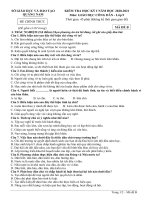
FIG. 1 Relation of Test Coupons and Test Specimens to Rolling
Direction or Extension (Applicable to General Wrought Products)
Copyright by ASTM Int'l (all rights reserved); Fri Sep 25 07:43:46 EDT 2020
2
Downloaded/printed by
University of Michigan (University of Michigan) pursuant to License Agreement. No further reproductions authorized.
A370 − 20
FIG. 2 Location of Longitudinal Tension Test Specimens in Rings Cut From Tubular Products
between values obtained at 100 and 0 % fibrous fracture, and
(4) the temperature corresponding to a specific energy value.
3.2.5 transverse test, n—unless specifically defined
otherwise, signifies that the lengthwise axis of the specimen is
right angles to the direction of the greatest extension of the
steel during rolling or forging.
3.2.5.1 Discussion—The stress applied to a transverse tension test specimen is at right angles to the greatest extension,
and the axis of the fold of a transverse bend test specimen is
parallel to the greatest extension (see Fig. 1).
Copyright by ASTM Int'l (all rights reserved); Fri Sep 25 07:43:46 EDT 2020
3
Downloaded/printed by
University of Michigan (University of Michigan) pursuant to License Agreement. No further reproductions authorized.
A370 − 20
3.3 Definition of Terms Specific to the Procedure for Use
and Control of Heat-cycle Simulation (See Annex A9):
3.3.1 master chart, n—a record of the heat treatment received from a forging essentially identical to the production
forgings that it will represent.
3.3.1.1 Discussion—It is a chart of time and temperature
showing the output from thermocouples imbedded in the
forging at the designated test immersion and test location or
locations.
3.3.2 program chart, n—the metallized sheet used to program the simulator unit.
3.3.2.1 Discussion—Time-temperature data from the master
chart are manually transferred to the program chart.
3.3.3 simulator chart, n—a record of the heat treatment that
a test specimen had received in the simulator unit.
3.3.3.1 Discussion—It is a chart of time and temperature
and can be compared directly to the master chart for accuracy
of duplication.
3.3.4 simulator cycle, n—one continuous heat treatment of a
set of specimens in the simulator unit.
3.3.4.1 Discussion—The cycle includes heating from
ambient, holding at temperature, and cooling. For example, a
simulated austenitize and quench of a set of specimens would
be one cycle; a simulated temper of the same specimens would
be another cycle.
4. Significance and Use
4.1 The primary use of these test methods is testing to
determine the specified mechanical properties of steel, stainless
steel, and related alloy products for the evaluation of conformance of such products to a material specification under the
jurisdiction of ASTM Committee A01 and its subcommittees as
designated by a purchaser in a purchase order or contract.
4.1.1 These test methods may be and are used by other
ASTM Committees and other standards writing bodies for the
purpose of conformance testing.
4.1.2 The material condition at the time of testing, sampling
frequency, specimen location and orientation, reporting
requirements, and other test parameters are contained in the
pertinent material specification or in a general requirement
specification for the particular product form.
4.1.3 Some material specifications require the use of additional test methods not described herein; in such cases, the
required test method is described in that material specification
or by reference to another appropriate test method standard.
4.2 These test methods are also suitable to be used for
testing of steel, stainless steel and related alloy materials for
other purposes, such as incoming material acceptance testing
by the purchaser or evaluation of components after service
exposure.
4.2.1 As with any mechanical testing, deviations from either
specification limits or expected as-manufactured properties can
occur for valid reasons besides deficiency of the original
as-fabricated product. These reasons include, but are not
limited to: subsequent service degradation from environmental
exposure (for example, temperature, corrosion); static or cyclic
service stress effects, mechanically-induced damage, material
inhomogeneity, anisotropic structure, natural aging of select
alloys, further processing not included in the specification,
sampling limitations, and measuring equipment calibration
uncertainty. There is statistical variation in all aspects of
mechanical testing and variations in test results from prior tests
are expected. An understanding of possible reasons for deviation from specified or expected test values should be applied in
interpretation of test results.
5. General Precautions
5.1 Certain methods of fabrication, such as bending,
forming, and welding, or operations involving heating, may
affect the properties of the material under test. Therefore, the
product specifications cover the stage of manufacture at which
mechanical testing is to be performed. The properties shown by
testing prior to fabrication may not necessarily be representative of the product after it has been completely fabricated.
5.2 Improperly machined specimens should be discarded
and other specimens substituted.
5.3 Flaws in the specimen may also affect results. If any test
specimen develops flaws, the retest provision of the applicable
product specification shall govern.
5.4 If any test specimen fails because of mechanical reasons
such as failure of testing equipment or improper specimen
preparation, it may be discarded and another specimen taken.
6. Orientation of Test Specimens
6.1 The terms “longitudinal test” and “transverse test” are
used only in material specifications for wrought products and
are not applicable to castings. When such reference is made to
a test coupon or test specimen, see Section 3 for terms and
definitions.
TENSION TEST
7. Description
7.1 The tension test related to the mechanical testing of steel
products subjects a machined or full-section specimen of the
material under examination to a measured load sufficient to
cause rupture. The resulting properties sought are defined in
Terminology E6.
7.2 In general, the testing equipment and methods are given
in Test Methods E8/E8M. However, there are certain exceptions to Test Methods E8/E8M practices in the testing of steel,
and these are covered in these test methods.
8. Testing Apparatus and Operations
8.1 Loading Systems—There are two general types of loading systems, mechanical (screw power) and hydraulic. These
differ chiefly in the variability of the rate of load application.
The older screw power machines are limited to a small number
of fixed free running crosshead speeds. Some modern screw
power machines, and all hydraulic machines permit stepless
variation throughout the range of speeds.
8.2 The tension testing machine shall be maintained in good
operating condition, used only in the proper loading range, and
calibrated periodically in accordance with the latest revision of
Practices E4.
Copyright by ASTM Int'l (all rights reserved); Fri Sep 25 07:43:46 EDT 2020
4
Downloaded/printed by
University of Michigan (University of Michigan) pursuant to License Agreement. No further reproductions authorized.
A370 − 20
NOTE 2—Many machines are equipped with stress-strain recorders for
autographic plotting of stress-strain curves. It should be noted that some
recorders have a load measuring component entirely separate from the
load indicator of the testing machine. Such recorders are calibrated
separately.
8.3 Loading—It is the function of the gripping or holding
device of the testing machine to transmit the load from the
heads of the machine to the specimen under test. The essential
requirement is that the load shall be transmitted axially. This
implies that the centers of the action of the grips shall be in
alignment, insofar as practicable, with the axis of the specimen
at the beginning and during the test and that bending or
twisting be held to a minimum. For specimens with a reduced
section, gripping of the specimen shall be restricted to the grip
section. In the case of certain sections tested in full size,
nonaxial loading is unavoidable and in such cases shall be
permissible.
8.4 Speed of Testing—The speed of testing shall not be
greater than that at which load and strain readings can be made
accurately. In production testing, speed of testing is commonly
expressed: (1) in terms of free running crosshead speed (rate of
movement of the crosshead of the testing machine when not
under load), (2) in terms of rate of separation of the two heads
of the testing machine under load, (3) in terms of rate of
stressing the specimen, or (4) in terms of rate of straining the
specimen. The following limitations on the speed of testing are
recommended as adequate for most steel products:
NOTE 3—Tension tests using closed-loop machines (with feedback
control of rate) should not be performed using load control, as this mode
of testing will result in acceleration of the crosshead upon yielding and
elevation of the measured yield strength.
8.4.1 Any convenient speed of testing may be used up to
one half the specified yield point or yield strength. When this
point is reached, the free-running rate of separation of the
crossheads shall be adjusted so as not to exceed 1⁄16 in. per min
per inch of reduced section, or the distance between the grips
for test specimens not having reduced sections. This speed
shall be maintained through the yield point or yield strength. In
determining the tensile strength, the free-running rate of
separation of the heads shall not exceed 1⁄2 in. per min per inch
of reduced section, or the distance between the grips for test
specimens not having reduced sections. In any event, the
minimum speed of testing shall not be less than 1⁄10 the
specified maximum rates for determining yield point or yield
strength and tensile strength.
8.4.2 It shall be permissible to set the speed of the testing
machine by adjusting the free running crosshead speed to the
above specified values, inasmuch as the rate of separation of
heads under load at these machine settings is less than the
specified values of free running crosshead speed.
8.4.3 As an alternative, if the machine is equipped with a
device to indicate the rate of loading, the speed of the machine
from half the specified yield point or yield strength through the
yield point or yield strength may be adjusted so that the rate of
stressing does not exceed 100 000 psi (690 MPa) ⁄min.
However, the minimum rate of stressing shall not be less than
10 000 psi (70 MPa)/min.
9. Test Specimen Parameters
9.1 Selection—Test coupons shall be selected in accordance
with the applicable product specifications.
9.1.1 Wrought Steels—Wrought steel products are usually
tested in the longitudinal direction, but in some cases, where
size permits and the service justifies it, testing is in the
transverse, radial, or tangential directions (see Figs. 1 and 2).
9.1.2 Forged Steels—For open die forgings, the metal for
tension testing is usually provided by allowing extensions or
prolongations on one or both ends of the forgings, either on all
or a representative number as provided by the applicable
product specifications. Test specimens are normally taken at
mid-radius. Certain product specifications permit the use of a
representative bar or the destruction of a production part for
test purposes. For ring or disk-like forgings test metal is
provided by increasing the diameter, thickness, or length of the
forging. Upset disk or ring forgings, which are worked or
extended by forging in a direction perpendicular to the axis of
the forging, usually have their principal extension along
concentric circles and for such forgings tangential tension
specimens are obtained from extra metal on the periphery or
end of the forging. For some forgings, such as rotors, radial
tension tests are required. In such cases the specimens are cut
or trepanned from specified locations.
9.2 Size and Tolerances—Test specimens shall be (1) the
full cross section of material, or (2) machined to the form and
dimensions shown in Figs. 3-6. The selection of size and type
of specimen is prescribed by the applicable product specification. Full cross section specimens shall be tested in 8-in.
(200 mm) gauge length unless otherwise specified in the
product specification.
9.3 Procurement of Test Specimens—Specimens shall be
extracted by any convenient method taking care to remove all
distorted, cold-worked, or heat-affected areas from the edges of
the section used in evaluating the material. Specimens usually
have a reduced cross section at mid-length to ensure uniform
distribution of the stress over the cross section and localize the
zone of fracture.
9.4 Aging of Test Specimens—Unless otherwise specified, it
shall be permissible to age tension test specimens. The timetemperature cycle employed must be such that the effects of
previous processing will not be materially changed. It may be
accomplished by aging at room temperature 24 to 48 h, or in
shorter time at moderately elevated temperatures by boiling in
water, heating in oil or in an oven.
9.5 Measurement of Dimensions of Test Specimens:
9.5.1 Standard Rectangular Tension Test Specimens—These
forms of specimens are shown in Fig. 3. To determine the
cross-sectional area, the center width dimension shall be
measured to the nearest 0.005 in. (0.13 mm) for the 8-in. (200
mm) gauge length specimen and 0.001 in. (0.025 mm) for the
2-in. (50 mm) gauge length specimen in Fig. 3. The center
thickness dimension shall be measured to the nearest 0.001 in.
for both specimens.
9.5.2 Standard Round Tension Test Specimens—These
forms of specimens are shown in Fig. 4 and Fig. 5. To
determine the cross-sectional area, the diameter shall be
Copyright by ASTM Int'l (all rights reserved); Fri Sep 25 07:43:46 EDT 2020
5
Downloaded/printed by
University of Michigan (University of Michigan) pursuant to License Agreement. No further reproductions authorized.
A370 − 20
DIMENSIONS
Standard Specimens
Subsize Specimen
Plate-type,
11⁄2-in. (40 mm) Wide
8-in. (200 mm)
Gauge Length
G—Gauge length
(Notes 1 and 2)
W—Width
(Notes 3, 5, and 6)
T—Thickness
(Note 7)
R—Radius of fillet, min
(Note 4)
L—Overall length, min
(Notes 2 and 8)
A—Length of
reduced section, min
B—Length of grip section, min
(Note 9)
C—Width of grip section, approximate
(Note 4, Note 10, and Note 11)
2-in. (50 mm)
Gauge Length
Sheet-type, 1⁄2
in. (12.5 mm) Wide
⁄ -in. (6 mm) Wide
14
in.
mm
in.
mm
in.
mm
in.
mm
8.00 ± 0.01
200 ± 0.25
2.000 ± 0.005
50.0 ± 0.10
2.000 ± 0.005
50.0 ± 0.10
1.000 ± 0.003
25.0 ± 0.08
1 1⁄ 2 + 1⁄ 8
− 1⁄ 4
40 + 3
−6
1 1 ⁄2 + 1 ⁄8
− 1⁄ 4
40 + 3
−6
0.500 ± 0.010
12.5 ± 0.25
0.250 ± 0.002
6.25 ± 0.05
12
⁄
13
12
⁄
13
12
⁄
13
14
⁄
6
18
450
8
200
8
200
4
100
9
225
2 1⁄ 4
60
21⁄4
60
11⁄4
32
3
75
2
50
2
50
11⁄4
32
2
50
2
50
34
⁄
20
38
⁄
10
Thickness of Material
NOTE 1—For the 11⁄2-in. (40 mm) wide specimens, punch marks for measuring elongation after fracture shall be made on the flat or on the edge of
the specimen and within the reduced section. For the 8-in. (200 mm) gauge length specimen, a set of nine or more punch marks 1 in. (25 mm) apart,
or one or more pairs of punch marks 8 in. (200 mm) apart may be used. For the 2-in. (50 mm) gauge length specimen, a set of three or more punch marks
1 in. (25 mm) apart, or one or more pairs of punch marks 2 in. (50 mm) apart may be used.
NOTE 2—For the 1⁄2-in. (12.5 mm) wide specimen, punch marks for measuring the elongation after fracture shall be made on the flat or on the edge
of the specimen and within the reduced section. Either a set of three or more punch marks 1 in. (25 mm) apart or one or more pairs of punch marks 2 in.
(50 mm) apart may be used.
NOTE 3—For the four sizes of specimens, the ends of the reduced section shall not differ in width by more than 0.004, 0.004, 0.002, or 0.001 in. (0.10,
0.10, 0.05, or 0.025 mm), respectively. Also, there may be a gradual decrease in width from the ends to the center, but the width at either end shall not
be more than 0.015 in., 0.015 in., 0.005 in., or 0.003 in. (0.40, 0.40, 0.10, or 0.08 mm), respectively, larger than the width at the center.
NOTE 4—For each specimen type, the radii of all fillets shall be equal to each other with a tolerance of 0.05 in. (1.25 mm), and the centers of curvature
of the two fillets at a particular end shall be located across from each other (on a line perpendicular to the centerline) within a tolerance of 0.10 in.
(2.5 mm).
NOTE 5—For each of the four sizes of specimens, narrower widths (W and C) may be used when necessary. In such cases, the width of the reduced
section should be as large as the width of the material being tested permits; however, unless stated specifically, the requirements for elongation in a product
specification shall not apply when these narrower specimens are used. If the width of the material is less than W, the sides may be parallel throughout
the length of the specimen.
NOTE 6—The specimen may be modified by making the sides parallel throughout the length of the specimen, the width and tolerances being the same
as those specified above. When necessary, a narrower specimen may be used, in which case the width should be as great as the width of the material being
tested permits. If the width is 11⁄2 in. (38 mm) or less, the sides may be parallel throughout the length of the specimen.
NOTE 7—The dimension T is the thickness of the test specimen as provided for in the applicable product specification. Minimum nominal thickness
of 1 to 11⁄2-in. (40 mm) wide specimens shall be 3⁄16 in. (5 mm), except as permitted by the product specification. Maximum nominal thickness of 1⁄2-in.
(12.5 mm) and 1⁄4-in. (6 mm) wide specimens shall be 1 in. (25 mm) and 1⁄4 in. (6 mm), respectively.
NOTE 8—To aid in obtaining axial loading during testing of 1⁄4-in. (6 mm) wide specimens, the overall length should be as large as the material will
permit.
NOTE 9—It is desirable, if possible, to make the length of the grip section large enough to allow the specimen to extend into the grips a distance equal
to two thirds or more of the length of the grips. If the thickness of 1⁄2-in. (13 mm) wide specimens is over 3⁄8 in. (10 mm), longer grips and correspondingly
longer grip sections of the specimen may be necessary to prevent failure in the grip section.
NOTE 10—For standard sheet-type specimens and subsize specimens, the ends of the specimen shall be symmetrical with the center line of the reduced
section within 0.01 and 0.005 in. (0.25 and 0.13 mm), respectively, except that for steel if the ends of the 1⁄2-in. (12.5 mm) wide specimen are symmetrical
within 0.05 in. (1.0 mm), a specimen may be considered satisfactory for all but referee testing.
NOTE 11—For standard plate-type specimens, the ends of the specimen shall be symmetrical with the center line of the reduced section within 0.25 in.
(6.35 mm), except for referee testing in which case the ends of the specimen shall be symmetrical with the center line of the reduced section within 0.10 in.
(2.5 mm).
FIG. 3 Rectangular Tension Test Specimens
Copyright by ASTM Int'l (all rights reserved); Fri Sep 25 07:43:46 EDT 2020
6
Downloaded/printed by
University of Michigan (University of Michigan) pursuant to License Agreement. No further reproductions authorized.
A370 − 20
DIMENSIONS
Nominal Diameter
G—Gauge length
D—Diameter (Note 1)
R—Radius of fillet, min
A—Length of reduced section, min
(Note 2)
Standard Specimen
in.
mm
0.500
12.5
2.00±
50.0 ±
0.005
0.10
0.500±
12.5±
0.010
0.25
3⁄ 8
10
21⁄ 4
60
in.
0.350
1.400±
0.005
0.350±
0.007
1⁄ 4
13⁄4
mm
8.75
35.0 ±
0.10
8.75 ±
0.18
6
45
Small-size Specimens Proportional to Standard
in.
mm
in.
mm
0.250
6.25
0.160
4.00
1.000±
25.0 ±
0.640±
16.0 ±
0.005
0.10
0.005
0.10
0.250±
6.25 ±
0.160±
4.00 ±
0.005
0.12
0.003
0.08
3⁄16
5⁄32
5
4
3⁄ 4
11⁄4
32
20
in.
0.113
0.450±
0.005
0.113±
0.002
3⁄32
5⁄ 8
mm
2.50
10.0 ±
0.10
2.50 ±
0.05
2
16
NOTE 1—The reduced section may have a gradual taper from the ends toward the center, with the ends not more than 1 % larger in diameter than the
center (controlling dimension).
NOTE 2—If desired, the length of the reduced section may be increased to accommodate an extensometer of any convenient gauge length. Reference
marks for the measurement of elongation should, nevertheless, be spaced at the indicated gauge length.
NOTE 3—The gauge length and fillets shall be as shown, but the ends may be of any form to fit the holders of the testing machine in such a way that
the load shall be axial (see Fig. 9). If the ends are to be held in wedge grips it is desirable, if possible, to make the length of the grip section great enough
to allow the specimen to extend into the grips a distance equal to two thirds or more of the length of the grips.
NOTE 4—On the round specimens in Fig. 5 and Fig. 6, the gauge lengths are equal to four times the nominal diameter. In some product specifications
other specimens may be provided for, but unless the 4-to-1 ratio is maintained within dimensional tolerances, the elongation values may not be comparable
with those obtained from the standard test specimen.
NOTE 5—The use of specimens smaller than 0.250-in. (6.25 mm) diameter shall be restricted to cases when the material to be tested is of insufficient
size to obtain larger specimens or when all parties agree to their use for acceptance testing. Smaller specimens require suitable equipment and greater
skill in both machining and testing.
NOTE 6—Five sizes of specimens often used have diameters of approximately 0.505, 0.357, 0.252, 0.160, and 0.113 in., the reason being to permit easy
calculations of stress from loads, since the corresponding cross sectional areas are equal or close to 0.200, 0.100, 0.0500, 0.0200, and 0.0100 in.2,
respectively. Thus, when the actual diameters agree with these values, the stresses (or strengths) may be computed using the simple multiplying factors
5, 10, 20, 50, and 100, respectively. (The metric equivalents of these fixed diameters do not result in correspondingly convenient cross sectional area and
multiplying factors.)
FIG. 4 Standard 0.500-in. (12.5 mm) Round Tension Test Specimen With 2-in. (50 mm) Gauge Length and Examples of Small-size Specimens Proportional to Standard Specimens
measured at the center of the gauge length to the nearest
0.001 in. (0.025 mm) (see Table 1).
mm) gauge length specimen of Fig. 3 may be used for sheet and strip
material.
9.6 General—Test specimens shall be either substantially
full size or machined, as prescribed in the product specifications for the material being tested.
9.6.1 It is desirable to have the cross-sectional area of the
specimen smallest at the center of the gauge length to ensure
fracture within the gauge length. This is provided for by the
taper in the gauge length permitted for each of the specimens
described in the following sections.
9.6.2 For brittle materials it is desirable to have fillets of
large radius at the ends of the gauge length.
11. Sheet-type Specimen
10. Plate-type Specimens
10.1 The standard plate-type test specimens are shown in
Fig. 3. Such specimens are used for testing metallic materials
in the form of plate, structural and bar-size shapes, and flat
material having a nominal thickness of 3⁄16 in. (5 mm) or over.
When product specifications so permit, other types of specimens may be used.
NOTE 4—When called for in the product specification, the 8-in. (200
11.1 The standard sheet-type test specimen is shown in Fig.
3. This specimen is used for testing metallic materials in the
form of sheet, plate, flat wire, strip, band, and hoop ranging in
nominal thickness from 0.005 to 1 in. (0.13 to 25 mm). When
product specifications so permit, other types of specimens may
be used, as provided in Section 10 (see Note 4).
12. Round Specimens
12.1 The standard 0.500-in. (12.5 mm) diameter round test
specimen shown in Fig. 4 is frequently used for testing metallic
materials.
12.2 Fig. 4 also shows small size specimens proportional to
the standard specimen. These may be used when it is necessary
to test material from which the standard specimen or specimens
shown in Fig. 3 cannot be prepared. Other sizes of small round
specimens may be used. In any such small size specimen it is
important that the gauge length for measurement of elongation
be four times the diameter of the specimen (see Note 5, Fig. 4).
Copyright by ASTM Int'l (all rights reserved); Fri Sep 25 07:43:46 EDT 2020
7
Downloaded/printed by
University of Michigan (University of Michigan) pursuant to License Agreement. No further reproductions authorized.
A370 − 20
DIMENSIONS
Specimen 1
G—Gauge length
D—Diameter (Note 1)
R—Radius of fillet, min
A—Length of reduced
section
L—Overall length, approximate
B—Grip section
(Note 2)
C—Diameter of end section
E—Length of shoulder and
fillet section, approximate
F—Diameter of shoulder
Specimen 2
Specimen 3
Specimen 4
Specimen 5
in.
mm
in.
mm
in.
mm
in.
mm
in.
mm
2.000±
0.005
0.500 ±
0.010
3⁄8
21⁄4, min
50.0 ±
0.10
12.5±
0.25
10
60, min
2.000±
0.005
0.500 ±
0.010
3⁄ 8
21⁄4 , min
50.0 ±
0.10
12.5±
0.25
10
60, min
50.0 ±
0.10
12.5±
0.25
10
60, min
2.00±
0.005
0.500±
0.010
3⁄8
21⁄4 , min
50.0 ±
0.10
12.5 ±
0.25
10
60, min
125
35, approximately
20
...
140
25, approximately
20
16
50.0 ±
0.10
12.5±
0.25
2
100, approximately
140
20, approximately
18
...
2.000±
0.005
0.500 ±
0.010
3 ⁄8
21⁄4 , min
5
13⁄8 , approximately
3⁄4
...
2.000±
0.005
0.500 ±
0.010
1⁄16
4, approximately
51 ⁄ 2
3⁄4 , approximately
23⁄32
...
120
13, approximately
22
20
91 ⁄ 2
3, min
240
75, min
58
⁄
⁄
20
16
...
...
16
...
...
58
⁄
15
51⁄2
1, approximately
3⁄ 4
5⁄ 8
⁄
58
43 ⁄ 4
⁄ , approximately
7 ⁄8
3 ⁄4
12
⁄
34
16
19 32
NOTE 1—The reduced section may have a gradual taper from the ends toward the center with the ends not more than 0.005 in. (0.10 mm) larger in
diameter than the center.
NOTE 2—On Specimen 5 it is desirable, if possible, to make the length of the grip section great enough to allow the specimen to extend into the grips
a distance equal to two thirds or more of the length of the grips.
NOTE 3—The types of ends shown are applicable for the standard 0.500-in. round tension test specimen; similar types can be used for subsize
specimens. The use of UNF series of threads (3⁄4 by 16, 1⁄2 by 20, 3⁄8 by 24, and 1⁄4 by 28) is suggested for high-strength brittle materials to avoid fracture
in the thread portion.
FIG. 5 Suggested Types of Ends for Standard Round Tension Test Specimens
DIMENSIONS
Specimen 1
in.
G—Length of parallel
D—Diameter
R—Radius of fillet, min
A—Length of reduced section, min
L—Over-all length, min
B—Grip section, approximate
C—Diameter of end section, approximate
E—Length of shoulder, min
F—Diameter of shoulder
Specimen 2
mm
in.
Shall be equal to or greater than diameter D
0.500 ± 0.010
12.5± 0.25
0.750 ± 0.015
1
25
1
11⁄4
32
1 1 ⁄2
95
4
33⁄4
1
25
1
3⁄ 4
20
1 1 ⁄8
1⁄ 4
1⁄ 4
6
5⁄8 ± 1⁄64
15⁄16 ± 1⁄64
16.0 ± 0.40
Specimen 3
mm
in.
mm
20.0 ± 0.40
25
38
100
25
30
6
24.0 ± 0.40
1.25 ± 0.025
2
2 1⁄4
63⁄8
13⁄4
1 7⁄8
5⁄16
17⁄16 ± 1⁄64
30.0 ± 0.60
50
60
160
45
48
8
36.5 ± 0.40
NOTE 1—The reduced section and shoulders (dimensions A, D, E, F, G, and R) shall be shown, but the ends may be of any form to fit the holders of
the testing machine in such a way that the load shall be axial. Commonly the ends are threaded and have the dimensions B and C given above.
FIG. 6 Standard Tension Test Specimens for Cast Iron
Copyright by ASTM Int'l (all rights reserved); Fri Sep 25 07:43:46 EDT 2020
8
Downloaded/printed by
University of Michigan (University of Michigan) pursuant to License Agreement. No further reproductions authorized.
A370 − 20
TABLE 1 Multiplying Factors to Be Used for Various Diameters of Round Test Specimens
Standard Specimen
Small Size Specimens Proportional to Standard
0.500 in. Round
Actual
Diameter,
in.
Area,
in.2
0.490
0.491
0.492
0.493
0.494
0.495
0.496
0.250 in. Round
Multiplying
Factor
Actual
Diameter,
in.
Area,
in.2
Multiplying
Factor
Actual
Diameter,
in.
0.1886
0.1893
0.1901
0.1909
0.1917
0.1924
0.1932
5.30
5.28
5.26
5.24
5.22
5.20
5.18
0.343
0.344
0.345
0.346
0.347
0.348
0.349
0.0924
0.0929
0.0935
0.0940
0.0946
0.0951
0.0957
10.82
10.76
10.70
10.64
10.57
10.51
10.45
0.245
0.246
0.247
0.248
0.249
0.250
0.251
0.497
0.1940
5.15
0.350
0.0962
10.39
0.252
0.498
0.1948
5.13
0.351
0.0968
10.33
0.253
0.499
0.500
0.501
0.502
0.503
0.1956
0.1963
0.1971
0.1979
0.1987
5.11
5.09
5.07
5.05
5.03
0.352
0.353
0.354
0.355
0.356
0.504
0.1995
(0.2)A
0.2003
(0.2)A
0.2011
(0.2)A
0.2019
0.2027
0.2035
0.2043
5.01
(5.0)A
4.99
(5.0)A
4.97
(5.0)A
4.95
4.93
4.91
4.90
0.357
...
0.0973
0.0979
0.0984
0.0990
0.0995
(0.1)A
0.1001
(0.1)A
...
10.28
10.22
10.16
10.10
10.05
(10.0)A
9.99
(10.0)A
...
...
...
...
...
...
...
...
...
...
...
0.505
0.506
0.507
0.508
0.509
0.510
A
0.350 in. Round
Area,
in.2
Multiplying
Factor
0.254
0.255
...
...
...
...
...
...
...
0.0471
0.0475
0.0479
0.0483
0.0487
0.0491
0.0495
(0.05)A
0.0499
(0.05)A
0.0503
(0.05)A
0.0507
0.0511
...
...
...
...
...
...
...
21.21
21.04
20.87
20.70
20.54
20.37
20.21
(20.0)A
20.05
(20.0)A
19.89
(20.0)A
19.74
19.58
...
...
...
...
...
...
...
...
...
...
...
...
...
...
...
...
...
...
...
...
...
...
...
...
...
...
...
The values in parentheses may be used for ease in calculation of stresses, in pounds per square inch, as permitted in Note 5 of Fig. 4.
12.3 The type of specimen ends outside of the gauge length
shall accommodate the shape of the product tested, and shall
properly fit the holders or grips of the testing machine so that
axial loads are applied with a minimum of load eccentricity and
slippage. Fig. 5 shows specimens with various types of ends
that have given satisfactory results.
13. Gauge Marks
13.1 The specimens shown in Figs. 3-6 shall be gauge
marked with a center punch, scribe marks, multiple device, or
drawn with ink. The purpose of these gauge marks is to
determine the percent elongation. Punch marks shall be light,
sharp, and accurately spaced. The localization of stress at the
marks makes a hard specimen susceptible to starting fracture at
the punch marks. The gauge marks for measuring elongation
after fracture shall be made on the flat or on the edge of the flat
tension test specimen and within the parallel section; for the
8-in. gauge length specimen, Fig. 3, one or more sets of 8-in.
gauge marks may be used, intermediate marks within the gauge
length being optional. Rectangular 2-in. gauge length
specimens, Fig. 3, and round specimens, Fig. 4, are gauge
marked with a double-pointed center punch or scribe marks.
One or more sets of gauge marks may be used; however, one
set must be approximately centered in the reduced section.
These same precautions shall be observed when the test
specimen is full section.
14. Determination of Tensile Properties
14.1 Yield Point—Yield point is the first stress in a material,
less than the maximum obtainable stress, at which an increase
in strain occurs without an increase in stress. Yield point is
intended for application only for materials that may exhibit the
unique characteristic of showing an increase in strain without
an increase in stress. The stress-strain diagram is characterized
by a sharp knee or discontinuity. Determine yield point by one
of the following methods:
14.1.1 Drop of Beam or Halt of Pointer Method—In this
method, apply an increasing load to the specimen at a uniform
rate. When a lever and poise machine is used, keep the beam in
balance by running out the poise at approximately a steady
rate. When the yield point of the material is reached, the
increase of the load will stop, but run the poise a trifle beyond
the balance position, and the beam of the machine will drop for
a brief but appreciable interval of time. When a machine
equipped with a load-indicating dial is used there is a halt or
hesitation of the load-indicating pointer corresponding to the
Copyright by ASTM Int'l (all rights reserved); Fri Sep 25 07:43:46 EDT 2020
9
Downloaded/printed by
University of Michigan (University of Michigan) pursuant to License Agreement. No further reproductions authorized.
A370 − 20
drop of the beam. Note the load at the “drop of the beam” or
the “halt of the pointer” and record the corresponding stress as
the yield point.
14.1.2 Autographic Diagram Method—When a sharp-kneed
stress-strain diagram is obtained by an autographic recording
device, take the stress corresponding to the top of the knee
(Fig. 7), or the stress at which the curve drops as the yield
point.
14.1.3 Total Extension Under Load Method—When testing
material for yield point and the test specimens may not exhibit
a well-defined disproportionate deformation that characterizes
a yield point as measured by the drop of the beam, halt of the
pointer, or autographic diagram methods described in 14.1.1
and 14.1.2, a value equivalent to the yield point in its practical
significance may be determined by the following method and
may be recorded as yield point: Attach a Class C or better
extensometer (Notes 5 and 6) to the specimen. When the load
producing a specified extension (Note 7) is reached record the
stress corresponding to the load as the yield point (Fig. 8).
NOTE 5—Automatic devices are available that determine the load at the
specified total extension without plotting a stress-strain curve. Such
devices may be used if their accuracy has been demonstrated. Multiplying
calipers and other such devices are acceptable for use provided their
accuracy has been demonstrated as equivalent to a Class C extensometer.
NOTE 6—Reference should be made to Practice E83.
NOTE 7—For steel with a yield point specified not over 80 000 psi
(550 MPa), an appropriate value is 0.005 in./in. of gauge length. For
values above 80 000 psi, this method is not valid unless the limiting total
extension is increased.
NOTE 8—The shape of the initial portion of an autographically
determined stress-strain (or a load-elongation) curve may be influenced by
numerous factors such as the seating of the specimen in the grips, the
straightening of a specimen bent due to residual stresses, and the rapid
loading permitted in 8.4.1. Generally, the aberrations in this portion of the
curve should be ignored when fitting a modulus line, such as that used to
determine the extension-under-load yield, to the curve. In practice, for a
number of reasons, the straight-line portion of the stress-strain curve may
not go through the origin of the stress-strain diagram. In these cases it is
not the origin of the stress-strain diagram, but rather where the straightline portion of the stress-strain curve, intersects the strain axis that is
pertinent. All offsets and extensions should be calculated from the
intersection of the straight-line portion of the stress-strain curve with the
strain axis, and not necessarily from the origin of the stress-strain diagram.
See also Test Methods E8/E8M, Note 32.
14.2 Yield Strength—Yield strength is the stress at which a
material exhibits a specified limiting deviation from the proportionality of stress to strain. The deviation is expressed in
terms of strain, percent offset, total extension under load, and
so forth. Determine yield strength by one of the following
methods:
14.2.1 Offset Method—To determine the yield strength by
the “offset method,” it is necessary to secure data (autographic
or numerical) from which a stress-strain diagram with a distinct
modulus characteristic of the material being tested may be
drawn. Then on the stress-strain diagram (Fig. 9) lay off Om
equal to the specified value of the offset, draw mn parallel to
OA, and thus locate r, the intersection of mn with the
stress-strain curve corresponding to load R, which is the
yield-strength load. In recording values of yield strength
obtained by this method, the value of offset specified or used,
or both, shall be stated in parentheses after the term yield
strength, for example:
Yield strength ~ 0.2 % offset! 5 52 000 psi ~ 360 MPa!
(1)
When the offset is 0.2 % or larger, the extensometer used
shall qualify as a Class B2 device over a strain range of 0.05 to
1.0 %. If a smaller offset is specified, it may be necessary to
specify a more accurate device (that is, a Class B1 device) or
reduce the lower limit of the strain range (for example, to
0.01 %) or both. See also Note 10 for automatic devices.
NOTE 9—For stress-strain diagrams not containing a distinct modulus,
such as for some cold-worked materials, it is recommended that the
extension under load method be utilized. If the offset method is used for
materials without a distinct modulus, a modulus value appropriate for the
material being tested should be used: 30 000 000 psi (207 000 MPa) for
carbon steel; 29 000 000 psi (200 000 MPa) for ferritic stainless steel;
28 000 000 psi (193 000 MPa) for austenitic stainless steel. For special
alloys, the producer should be contacted to discuss appropriate modulus
values.
14.2.2 Extension Under Load Method—For tests to determine the acceptance or rejection of material whose stress-strain
characteristics are well known from previous tests of similar
material in which stress-strain diagrams were plotted, the total
strain corresponding to the stress at which the specified offset
(see Notes 10 and 11) occurs will be known within satisfactory
limits. The stress on the specimen, when this total strain is
reached, is the value of the yield strength. In recording values
of yield strength obtained by this method, the value of
“extension” specified or used, or both, shall be stated in
parentheses after the term yield strength, for example:
Yield strength ~ 0.5 % EUL! 5 52 000 psi ~ 360 MPa!
(2)
The total strain can be obtained satisfactorily by use of a
Class B1 extensometer (Note 5, Note 6, and Note 8).
NOTE 10—Automatic devices are available that determine offset yield
strength without plotting a stress-strain curve. Such devices may be used
if their accuracy has been demonstrated.
NOTE 11—The appropriate magnitude of the extension under load will
obviously vary with the strength range of the particular steel under test. In
general, the value of extension under load applicable to steel at any
strength level may be determined from the sum of the proportional strain
and the plastic strain expected at the specified yield strength. The
following equation is used:
Extension under load, in./in. of gauge length 5 ~ YS/E ! 1r
(3)
where:
YS = specified yield strength, psi or MPa,
E = modulus of elasticity, psi or MPa, and
r
= limiting plastic strain, in./in.
14.3 Tensile Strength—Calculate the tensile strength by
dividing the maximum load the specimen sustains during a
tension test by the original cross-sectional area of the specimen. If the upper yield strength is the maximum stress
recorded and if the stress-strain curve resembles that of Test
Methods E8/E8M–15a Fig. 25, the maximum stress after
discontinuous yielding shall be reported as the tensile strength
unless otherwise stated by the purchaser.
14.4 Elongation:
14.4.1 Fit the ends of the fractured specimen together
carefully and measure the distance between the gauge marks to
the nearest 0.01 in. (0.25 mm) for gauge lengths of 2 in. and
under, and to the nearest 0.5 % of the gauge length for gauge
Copyright by ASTM Int'l (all rights reserved); Fri Sep 25 07:43:46 EDT 2020
10
Downloaded/printed by
University of Michigan (University of Michigan) pursuant to License Agreement. No further reproductions authorized.
A370 − 20
lengths over 2 in. A percentage scale reading to 0.5 % of the
gauge length may be used. The elongation is the increase in
length of the gauge length, expressed as a percentage of the
original gauge length. In recording elongation values, give both
the percentage increase and the original gauge length.
14.4.2 If any part of the fracture takes place outside of the
middle half of the gauge length or in a punched or scribed mark
within the reduced section, the elongation value obtained may
not be representative of the material. If the elongation so
measured meets the minimum requirements specified, no
further testing is indicated, but if the elongation is less than the
minimum requirements, discard the test and retest.
14.4.3 Automated tensile testing methods using extensometers allow for the measurement of elongation in a method
described below. Elongation may be measured and reported
either this way, or as in the method described above, fitting the
broken ends together. Either result is valid.
14.4.4 Elongation at fracture is defined as the elongation
measured just prior to the sudden decrease in force associated
with fracture. For many ductile materials not exhibiting a
sudden decrease in force, the elongation at fracture can be
taken as the strain measured just prior to when the force falls
below 10 % of the maximum force encountered during the test.
14.4.4.1 Elongation at fracture shall include elastic and
plastic elongation and may be determined with autographic or
automated methods using extensometers verified over the
strain range of interest. Use a class B2 or better extensometer
for materials having less than 5 % elongation; a class C or
better extensometer for materials having elongation greater
than or equal to 5 % but less than 50 %; and a class D or better
extensometer for materials having 50 % or greater elongation.
In all cases, the extensometer gauge length shall be the nominal
gauge length required for the specimen being tested. Due to the
lack of precision in fitting fractured ends together, the elongation after fracture using the manual methods of the preceding
paragraphs may differ from the elongation at fracture determined with extensometers.
14.4.4.2 Percent elongation at fracture may be calculated
directly from elongation at fracture data and be reported
instead of percent elongation as calculated in 14.4.1. However,
these two parameters are not interchangeable. Use of the
elongation at fracture method generally provides more repeatable results.
14.5 Reduction of Area—Fit the ends of the fractured
specimen together and measure the mean diameter or the width
and thickness at the smallest cross section to the same accuracy
as the original dimensions. The difference between the area
thus found and the area of the original cross section expressed
as a percentage of the original area is the reduction of area.
FIG. 7 Stress-strain Diagram Showing Yield Point Corresponding
With Top of Knee
FIG. 8 Stress-strain Diagram Showing Yield Point or Yield
Strength by Extension Under Load Method
Copyright by ASTM Int'l (all rights reserved); Fri Sep 25 07:43:46 EDT 2020
11
Downloaded/printed by
University of Michigan (University of Michigan) pursuant to License Agreement. No further reproductions authorized.
A370 − 20
another or to approximate tensile strength. These conversion
values have been obtained from computer-generated curves
and are presented to the nearest 0.1 point to permit accurate
reproduction of those curves. All converted hardness values
must be considered approximate. All converted Rockwell and
Vickers hardness numbers shall be rounded to the nearest
whole number.
16.2 Hardness Testing:
16.2.1 If the product specification permits alternative hardness testing to determine conformance to a specified hardness
requirement, the conversions listed in Tables 2-5 shall be used.
16.2.2 When recording converted hardness numbers, the
measured hardness and test scale shall be indicated in
parentheses, for example: 353 HBW (38 HRC). This means
that a hardness value of 38 was obtained using the Rockwell C
scale and converted to a Brinell hardness of 353.
FIG. 9 Stress-strain Diagram for Determination of Yield Strength
by Offset Method
BEND TEST
17. Brinell Test
17.1 Description:
17.1.1 A specified load is applied to a flat surface of the
specimen to be tested, through a tungsten carbide ball of
specified diameter. The average diameter of the indentation is
used as a basis for calculation of the Brinell hardness number.
The quotient of the applied load divided by the area of the
surface of the indentation, which is assumed to be spherical, is
termed the Brinell hardness number (HBW) in accordance with
the following equation:
~
HBW 5 P/ @ ~ πD/2 ! D 2 =D 2 2 d 2
15. Description
15.1 The bend test is one method for evaluating ductility,
but it cannot be considered as a quantitative means of predicting service performance in all bending operations. The severity
of the bend test is primarily a function of the angle of bend of
the inside diameter to which the specimen is bent, and of the
cross section of the specimen. These conditions are varied
according to location and orientation of the test specimen and
the chemical composition, tensile properties, hardness, type,
and quality of the steel specified. Test Methods E190 and E290
may be consulted for methods of performing the test.
15.2 Unless otherwise specified, it shall be permissible to
age bend test specimens. The time-temperature cycle employed
must be such that the effects of previous processing will not be
materially changed. It may be accomplished by aging at room
temperature 24 to 48 h, or in shorter time at moderately
elevated temperatures by boiling in water or by heating in oil
or in an oven.
15.3 Bend the test specimen at room temperature to an
inside diameter, as designated by the applicable product
specifications, to the extent specified. The speed of bending is
ordinarily not an important factor.
HARDNESS TEST
16. General
16.1 A hardness test is a means of determining resistance to
penetration and is occasionally employed to obtain a quick
approximation of tensile strength. Tables 2-5 are for the
conversion of hardness measurements from one scale to
where:
HBW
P
D
d
=
=
=
=
!#
(4)
Brinell hardness number,
applied load, kgf,
diameter of the tungsten carbide ball, mm, and
average diameter of the indentation, mm.
NOTE 12—The Brinell hardness number is more conveniently secured
from standard tables such as Table 6, which show numbers corresponding
to the various indentation diameters, usually in increments of 0.05 mm.
NOTE 13—In Test Method E10 the values are stated in SI units, whereas
in this section kg/m units are used.
17.1.2 The standard Brinell test using a 10 mm tungsten
carbide ball employs a 3000 kgf load for hard materials and a
1500 or 500 kgf load for thin sections or soft materials (see
Annex A2 on Steel Tubular Products). Other loads and different size indentors may be used when specified. In recording
hardness values, the diameter of the ball and the load must be
stated except when a 10 mm ball and 3000 kgf load are used.
17.1.3 A range of hardness can properly be specified only
for quenched and tempered or normalized and tempered
material. For annealed material a maximum figure only should
be specified. For normalized material a minimum or a maximum hardness may be specified by agreement. In general, no
hardness requirements should be applied to untreated material.
17.1.4 Brinell hardness may be required when tensile properties are not specified.
17.2 Apparatus—Equipment shall meet the following requirements:
17.2.1 Testing Machine—A Brinell hardness testing machine is acceptable for use over a loading range within which
its load measuring device is accurate to 61 %.
Copyright by ASTM Int'l (all rights reserved); Fri Sep 25 07:43:46 EDT 2020
12
Downloaded/printed by
University of Michigan (University of Michigan) pursuant to License Agreement. No further reproductions authorized.
A370 − 20
NOTE 1—Metric equivalent: 1 in. = 25.4 mm.
Test Specimen Thickness, in.
3⁄ 8
t
A
1 1⁄ 2
4t
34
B
⁄
2t
C
2 3⁄ 8
6t + 1⁄8
D
13⁄16
3t + 1⁄16
⁄
t
2 1⁄ 2
6 2⁄ 3 t
1 1⁄ 4
3 1⁄ 3 t
33⁄8
8 2⁄ 3 t + 1⁄ 8
111⁄16
41⁄2 t + 1⁄16
38
Material
Materials with a specified minimum tensile strength of 95 ksi or
greater.
FIG. A2.15 Guided-bend Test Jig
A3. STEEL FASTENERS
A3.1 Scope
A3.1.1 This annex contains testing requirements for Steel
Fasteners that are specific to the product. The requirements
contained in this annex are supplementary to those found in the
general section of this specification. In the case of conflict
between requirements provided in this annex and those found
in the general section of this specification, the requirements of
this annex shall prevail. In the case of conflict between
requirements provided in this annex and requirements found in
product specifications, the requirements found in the product
specification shall prevail.
A3.1.2 These tests are set up to facilitate production control
testing and acceptance testing with certain more precise tests to
be used for arbitration in case of disagreement over test results.
A3.2 Tension Tests
A3.2.1 It is preferred that bolts be tested full size, and it is
customary, when so testing bolts to specify a minimum
ultimate load in pounds, rather than a minimum ultimate
strength in pounds per square inch. Three times the bolt
nominal diameter has been established as the minimum bolt
length subject to the tests described in the remainder of this
section. Subsections A3.2.1.1 – A3.2.1.6 apply when testing
bolts full size. Subsection A3.2.1.4 shall apply where the
individual product specifications permit the use of machined
specimens.
A3.2.1.1 Proof Load—Due to particular uses of certain
classes of bolts it is desirable to be able to stress them, while
in use, to a specified value without obtaining any permanent
set. To be certain of obtaining this quality the proof load is
specified. The proof load test consists of stressing the bolt with
a specified load which the bolt must withstand without permanent set. An alternate test which determines yield strength of a
full size bolt is also allowed. Either of the following Methods,
1 or 2, may be used but Method 1 shall be the arbitration
method in case of any dispute as to acceptance of the bolts.
A3.2.1.2 Proof Load Testing Long Bolts—When fasteners
are too long to test in the available equipment they may be cut
to 8 6 0.125 in. and tested using Method 1. If there is a dispute
over results when testing the same part or lot of parts both full
size and cut to 8 in., the 8 in. test results shall be used to
determine acceptance.
(a) Method 1, Length Measurement—The overall length of
a straight bolt shall be measured at its true center line with an
instrument capable of measuring changes in length of
Copyright by ASTM Int'l (all rights reserved); Fri Sep 25 07:43:46 EDT 2020
36
Downloaded/printed by
University of Michigan (University of Michigan) pursuant to License Agreement. No further reproductions authorized.