Báo cáo " All-optical NAND and AND gates based on 3x3 general interference multimode interference couplers" pdf
Bạn đang xem bản rút gọn của tài liệu. Xem và tải ngay bản đầy đủ của tài liệu tại đây (126 KB, 7 trang )
VNU Journal of Science, Mathematics - Physics 26 (2010) 107-113
107
All-optical NAND and AND gates based on 3x3 general
interference multimode interference couplers
Le Trung Thanh*
Department of Telecommunication Engineering, University of Transport and Communications
Received 23 March 2009
Abstract. This paper presents a new design method for all-optical NAND and AND logic gates
based on 3x3 general interference multimode interference (GI MMI) coupler. The whole device is
realized on the silicon on insulator (SOI) platform. The transfer matrix method (TMM) and three
dimensional beam propagation method (3D-BPM) are used to optimally design these devices.
Key words: Optical logic gate, multimode interference (MMI) coupler, silicon on insulator (SOI),
beam propagation method (BPM)
1. Introduction
All-optical logic gates are important elements in photonic signal processing systems. They have
many applications such as adders, subtractors, header recognizers, parity checkers, and encryption
systems. In practice, it is desirable to implement all-optical logic gates having small size, low power
consumption and high-speed [1, 2].
There are many existing approaches for realizing optical logic gates. Many materials and devices
have been suggested for use in optical logic. So far, optical logic schemes have been mainly based on
nonlinear materials [3, 4]. The disadvantage of these approaches is that high optical powers are needed
in order to obtain a nonlinear interaction. In addition, since the nonlinear coefficient is often small,
long interaction lengths are generally required. Moreover, devices based on nonlinear effects are not
always suitable for circuit integration. Another disadvantage is that nonlinear materials are usually
expensive [5-9].
A second approach for realizing optical logic is to use semiconductor optical amplifiers (SOAs).
SOAs are devices that amplify an optical signal without the use of optical-electrical-optical conversion
[10]. Amplification is achieved in materials that exhibit optical gain.
Recently, we have shown a general theory for realizing optical logic gates using MMI couplers
[11, 12]. In this paper, we show that all-optical NAND and AND logic gates based on 3x3 GI MMI
couplers can be realized. Moreover, silicon on insulator (SOI) technology is used for the design of
MMI devices because SOI technology is compatible with existing complementary metal–oxide–
semiconductor (CMOS) technologies for making compact, highly integrated, and multifunction
devices [13, 14]. The SOI platform uses silicon both as the substrate and the guiding core material.
The large index contrast between Si (
Si
n
=3.45 at wavelength 1550nm) and
2
SiO
(
2
SiO
n
=1.46) allows
______
*
Email:
L.T. Thanh / VNU Journal of Science, Mathematics - Physics 26 (2010) 107-113
108
light to be confined within submicron dimensions and single mode waveguides can have core cross-
sections with dimensions of only few hundred nanometres and bend radii of a few micrometers with
minimal losses. The designs for the devices are optimized by the 3D-BPM method.
2. Design of All-optical NAND and AND Gates based on 3x3 GI-MMI couplers
Theory: The conventional MMI coupler has a structure consisting of a homogeneous planar
multimode waveguide region connected to a number of single mode access waveguides [15]. The
MMI coupler can be operated using the general interference or restricted interference theory [16].
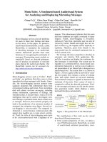
Consider a 3x3 GI-MMI coupler having a width of the MMI region
MMI
W , and a length
MMI
LL
π
=
as
shown in Fig. 1; where
(i=1,2,3) and b (1,2,3)
ij
aj= are the complex amplitudes of the signals at
input and output ports, respectively;
L
π
is the beat length of the MMI coupler [15].
Fig. 1. A 3x3 GI-MMI structure used for realizing optical logic gates.
Using the transfer matrix method [15], the relationship between the output complex amplitudes
j
b
(j=1,2,3) and the input complex amplitudes
i
a
(i=1,2,3) of the device can be expressed by
2/32/3
11
2/32/3
22
2/32/3
33
1
1
1
3
1
jj
jj
jj
beea
beea
beea
ππ
ππ
ππ
−−
−−
−−
−−
=−
−−
(1)
The amplitudes of signals at output ports 1, 2 and 3 may be rewritten as
22
33
1123
22
33
2123
22
33
3123
1
()
3
1
()
3
1
()
3
jj
jj
jj
beaeaa
beaaea
baeaea
ππ
ππ
ππ
−−
−−
−−
=−+−
=−+
=−+−
(2)
It will be shown that the phases and amplitudes of input beams can be adjusted properly in order to
achieve all-optical NAND and AND gates.
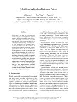
If phase shifters are added to input ports 1 and 3 of the MMI coupler as shown in Fig. 2 then an
all-optical NAND gate can be realized. It is assumed that a phase shifter having a phase shift of
2
3
π
−
is incorporated into input port 1, the signal
'
1
a
at the output of the phase shifter can be expressed by
L.T. Thanh / VNU Journal of Science, Mathematics - Physics 26 (2010) 107-113
109
2
'
3
11
j
aae
π
−
= (3)
Fig. 2. Structure for implementing a NAND gate based on a 3x3 GI-MMI coupler.
As a result, the new amplitude at output port 3 is given by
2
3
3123
1
()
3
j
beaaa
π
−
=−+−
(4)
If two optical attenuators are used at input ports 1 and 3 to reduce the input amplitudes by half,
then the complex amplitude at output port 3 is then given by
2
3
3213
11
[()]
2
3
j
beaaa
π
−
=−+
(5)
Equation (5) shows that the complex amplitude
3
b
at output port 3 is dependent of the complex
amplitudes at input ports 1, 2, and 3. When the signals at input ports 1, 2 and 3 have the same
amplitude and phase, the interference of these signals at output port 3 will be destructive. Thus, the
power at output port 3 will be zero for this case. For other cases, the power at output port 3 is non-
zero. This means that a NAND logic gate is formed at output port 3. It has two input ports (1 and 3)
and the output appears at output port 3. Input port 2 is used as a steady reference signal.
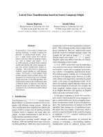
The 3D-BPM will now be used to verify the operating principle of the NAND gate. It is assumed that
the whole device is designed for the SOI platform. The waveguide cross-section is shown in Fig. 3.
Fig. 2. Silicon waveguide cross-section used in the designs.
L.T. Thanh / VNU Journal of Science, Mathematics - Physics 26 (2010) 107-113
110
The core thickness is
220
co
hnm
= and the access waveguide width is
500
a
Wnm
= . The width
MMI
W of the MMI coupler is large enough to limit crosstalk between two adjacent waveguides. In this
design, the width of the MMI coupler is chosen to be 6
MMI
Wm
µ
= . The length of the MMI coupler is
optimised by the 3D-BPM method and is found to be
99.8
MMI
Lm
µ
= at the operating wavelength of
1550
nm
λ
=
. The access waveguides are connected to the MMI waveguide via linear tapers having
the same length of 5
tp
Lm
µ
= to reduce excess losses.
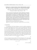
The 3D-BPM simulations for different input signals are shown in Fig. 3. The calculated excess
loss is 0.3dB for this gate.
(a) “0-0” (b) “0-1”
(c) “1-0 (d) “1-1”
Fig. 3. 3D-BPM simulations for a NAND logic gate with (a) input beams “0-0”, (b) input beams “0-1”, (c) input
beams “1-0” and (d) input beams “1-1”.
L.T. Thanh / VNU Journal of Science, Mathematics - Physics 26 (2010) 107-113
111
Note that if the choice for using no power in the output waveguide as logic “0” and having power
in the output waveguide as logic “1” is made, from the above 3D-BPM simulations, the truth table of
this NAND gate is shown in Table 1. The beams at input ports 1 and 2 can be written in the form
00
13
1 and 1
jj
aeae
== in order to show that these input beams have the same phase and amplitude. It
is also noted that the NAND gate has a small power at the output port for logic “1” and zero power for
logic “0”. In practice, the output signal can be amplified before being entered the decision circuit. This
requirement is not very difficult in electronics, but it may be challenging in the optical domain for
devices on the SOI platform.
Table 1. Truth table for a NAND gate and normalized output power
1
a
'
1
a
3
a
'
3
a
2
a
Normalized power at
output port 3,
2
3
b
Logic
level
0 0 0 0
1
j0
e
0.31 1
0 0
1
j0
e
0.5
j0
e
1
j0
e
0.077 1
j0
1e
j2/3
0.5e
−π
0 0
1
j0
e
0.077 1
j0
1e
j2/3
0.5e
−π
1
j0
e
0.5
j0
e
1
j0
e
0 0
Optical AND logic gate: When only two input ports 1 and 2 are used for input signals and input
port 3 is not used, an AND logic gate can be created at output port 2. Note that to function correctly,
the phase of the input signal beam at input port 2 is shifted by
/3
π
compared to that of the signal at
input port 1. The 3D-BPM simulations in Fig. 4 show the power distribution in the device for different
cases for input signals.
(a) “0-1” (b) “1-0” (c) “1-1”
Fig. 4. 3D-BPM simulations for an AND logic gate (a) input beams “0-1”, (b) input beams “1-0” and (c) input
beams “1-1”.
L.T. Thanh / VNU Journal of Science, Mathematics - Physics 26 (2010) 107-113
112
Table 2 presents the normalized output powers for different combinations of input signals. Thus
choosing a normalized threshold value of 0.78 (power unit) at the decision circuit for determining
whether bit “1” or bit “0” is received allows an AND gate to be formed. However, it is noted that the
threshold value of 0.78 for the decision circuit is very difficult to achieve using an optical decision
circuit. In practice, the fluctuation of input signals strongly affects the power level of output signals.
Thus, an AND gate based on MMI couplers is possible to be realized in theory, but may not be
realizable in practice.
Table 2. Method for obtaining an AND logic gate
1
a
2
a
Normalized power at
output port 2,
2
2
b
Threshold
value
Logic
level
0 0 0 0
0
1
j/3
e
π
0.31 0
j0
1e
0 0.31 0
j0
1e
1
j/3
e
π
1.26
0.5
1
3. Conclusion
In this paper we have shown that the realization of NAND and AND gates based on 3x3 general
interference multimode interference couplers is possible. The designs for these devices have been
implemented on the silicon on insulator platform and the 3D-BPM was used to optimize the device
structure.
References
[1] A.D. McAulay, Optical Computer Architectures: The Application of Optical Concepts to Next Generation
Computers, Wiley-Interscience, 1991.
[2] J. Hardy, J. Shamir, Optics inspired logic architecture, Optics Express, vol. 15 (2007) 150.
[3] D. Cotter, R.J. Manning, K.J.B. et. al., Non-linear Optics for High-Speed Digital Information Processing, Science,
vol. 286 (1999) 1523.
[4] Y. Wu, T. Shih, M. Chen, New all-optical logic gates based on the local nonlinear Mach-Zehnder interferometer,
Optics Express, vol. 16 (2008) 248.
[5] G. Cancellieri, F. Chiaraluce, E. Gambi, P. Pierleoni, Coupled-soliton photonic logic gates: practical design
procedures, Journal of the Optical Society of America B, vol. 12 (1995) 1300.
[6] Y.H. Pramono, M. Geshiro, T. Kitamura, S. Sawa, Optical logic OR, AND, NOT and NOR gates in waveguides
consisting of nonlinear material, IEICE Transactions on Electronics, vol. E83-C (2000) 1755.
[7] W. Youfa, L. Jianhua, All-fiber logical devices based on the nonlinear directional coupler, IEEE Photonics
Technology Letters, vol. 11 (1999) 72.
[8] M. Zitelli, E. Fazio, M. Bertolotti, All-optical NOR gate based on the interaction between cosine-shaped input
beams of orthogonal polarization, Journal of the Optical Society of America B, vol. 16 (1999) 214.
[9] M.N. Islam, Ultrafast all-optical logic gates based on soliton trapping in fibers, Optics Letters, vol. 14 (1989) 1257.
[10] M. J. Connelly, Semiconductor Optical Amplifiers, Springer, 2002.
L.T. Thanh / VNU Journal of Science, Mathematics - Physics 26 (2010) 107-113
113
[11] L.W. Cahill, T.T. Le, Photonic Signal Processing using MMI Elements, presented at 10th International Conference
on Transparent Optical Networks (ICTON 2008), Athens, Greece, 2008 (Invited paper).
[12] L. Cahill, T. Le, The design of signal processing devices employing SOI MMI couplers, presented at Paper 7220-2,
Integrated optoelectronic devices (OPTO 2009), Photonics West, Proceedings of the SPIE, San Jose Convention
Center, San Jose, California, USA, 24 - 29 January 2009.
[13] S. Janz, P. Cheben, D.D. e. al., Microphotonic elements for integration on the silicon-on-insulator waveguide
platform, IEEE Journal of Selected Topics in Quantum Electrononics, vol. 12 (2006) 1402.
[14] R. Soref, The past, present, and future of silicon photonics, IEEE Journal of Selected Topics in Quantum
Electrononics, vol. 12 (2006) 1678.
[15] T.T. Le, L.W. Cahill, The modeling of MMI structures for signal processing applications, Integrated Optics:
Devices, Materials, and Technologies XII. Edited by Greiner, Christoph M.; Waechter, Christoph A. Proceedings of
the SPIE, vol. 6896 (2008). 68961G-68961G-7.
[16] L.W. Cahill, T.T. Le, Modal Propagation Analysis Method for the Design of MMI Coupler Based Microring
Resonators, presented at Progress In Electromagnetics Research Symposium (PIERS) Proceedings, MIT,
Cambridge, USA, July 2-6, 2008.