properties of multilayer coatings produced by coaxial laser cladding
Bạn đang xem bản rút gọn của tài liệu. Xem và tải ngay bản đầy đủ của tài liệu tại đây (1.24 MB, 5 trang )
Home
Search
Collections
Journals
About
Contact us
My IOPscience
Properties of multilayer coatings produced by coaxial laser cladding
This content has been downloaded from IOPscience. Please scroll down to see the full text.
2016 J. Phys.: Conf. Ser. 747 012064
( />View the table of contents for this issue, or go to the journal homepage for more
Download details:
IP Address: 80.82.77.83
This content was downloaded on 28/02/2017 at 15:56
Please note that terms and conditions apply.
You may also be interested in:
Analysis of microstructure and properties of multilayer coatings produced by laser cladding
D P Bykovskiy, V N Petrovskiy, P S Dzhumaev et al.
Attenuation of laser power of a Gaussian beam
Jichang Liu, Lijun Li, Yuanzhong Zhang et al.
Wiring Implanted by Laser-Assisted Powder Jet Using Copper Microparticles
Katsuhiko Suzuki, Manabu Miura, Asahi Konno et al.
Efficiency of a copper vapor laser
Yu A Babeko, L A Vasil'ev, A V Sviridov et al.
High-power rhodamine 6G laser with an extended service life
B A Knyazev, S V Lebedev and E P Fokin
The spectrum and competition of autowaves in a wide-aperture laser with a saturable filter
A P Zaikin
II Conference on Plasma & Laser Research and Technologies
Journal of Physics: Conference Series 747 (2016) 012064
IOP Publishing
doi:10.1088/1742-6596/747/1/012064
Properties of multilayer coatings produced by coaxial laser
cladding
V N Petrovskiy1, D P Bykovskiy, P S Dzhumaev, V I Polskiy, N M Prokopova and
S N Chirikov
National Research Nuclear University MEPhI, Department of Laser Physics,
Kashirskoe highway 31, Moscow, Russia, 115409
E-mail:
Abstract. This article contains results of the study of multilayer coatings produced by laser
cladding on the substrate steel 34HMA using iron based powder PR-10R6M5 as the filler
material. The coatings were produced with consistent application of the tracks with fixed
overlapping. The dependencies between the characteristics of tracks and the technological
mode of deposition were revealed. Properties of coatings were determined for various
overlapping of tracks and directions of the cladding layers.
1. Introduction
Laser cladding is an additive technology for materials processing. It is an actively developing
processing technique, which is penetrating to the industry. This technology allows to create coating on
the surface of the workpiece to restore the damaged parts whose manufacturing is time-consuming and
expensive. In addition, claddings are used to impart desirable properties to the workpiece surface, e.g.
corrosion or wear resistance. The destruction of parts often starts with surface defects [1], thereby
laser cladding technology allows to improve part characteristics by creating layer with the desired
properties on the surface.
Apart from a laser, the energy source for cladding may be an arc, electron beam, plasma and others.
The laser cladding features the possibility of creating coatings with minimal heat affected zone (HAZ)
and minimal mixing of filler material with the substrate [1]. Wires, ribbons, or powders may be used
as a filler material. Cladding using a metal powder allows to achieve maximum uniformity of coating,
enables local surface treatment and producing any existing coating by mixing the powders. Other
advantages of laser cladding of powders were analyzed in more detail in [2–6].
2. Experimental equipment
Experimental equipment is shown in figure 1. Cladding processing cell (1) is equipped with a control
unit (2). Figure 2 shows the inside of the cell (1) consisting of a 5-axis positioning system, optical
head with water cooling and supply of protective gas and powder from the feeder (3) SulzerMetco
Twin 10-C, as well as an industrial digital camera for positioning parts and monitoring the process. As
an energy source we used fiber laser (4) LS-3.5 with power up to 3.5 kW, manufactured by IPG.
The metal powder is fed into the treatment zone via a coaxial nozzle. Under the impact of laser
radiation it is heating and melting. Simultaneously, the substrate surface is melting. The track is
produced during the motion of the nozzle relative to the substrate after cooling. New layers are formed
1
To whom any correspondence should be addressed.
Content from this work may be used under the terms of the Creative Commons Attribution 3.0 licence. Any further distribution
of this work must maintain attribution to the author(s) and the title of the work, journal citation and DOI.
Published under licence by IOP Publishing Ltd
1
II Conference on Plasma & Laser Research and Technologies
Journal of Physics: Conference Series 747 (2016) 012064
IOP Publishing
doi:10.1088/1742-6596/747/1/012064
by sequential application of tracks with some overlapping. Workpiece of the substrate was prepared
for cladding before the experiment. First, the cleaning of the working surface of samples with a wire
brush was performed. Then the work surface was treated by acetone wiping.
Figure 1. Experimental equipment.
Figure 2. View of optical head and
positioning system inside the cell.
3. Results of the cladding study
3.1. One track
Initially, we produced cladding of tracks with different technological modes and determined their
geometric characteristics: width and height of the track, and the depth of penetration of filler material
in the substrate. The measurements showed that the width of the cladding track and the filler material
penetration depth in the substrate are mainly influenced by a change of the laser power, while the
height of the tracks is mostly affected by the powder feed rate. We selected the most appropriate mode
for further research based on the following parameters: uniformity of the track form, the absence of
pores and cracks, the minimum level of mixing between substrate materials and powder, and a
minimum depth of penetration of filler material in the substrate combined with good adhesion of the
coating without delamination from the substrate.
Optimal mode for a single track cladding was selected in accordance with all the above mentioned
requirements: laser power 400 W, substrate movement speed 37.5 cm/min, powder feed rate 1 g/min,
and the height of the nozzle above the surface of 5 mm. We carried out a study of topography and
microstructure of the surface as well as the elemental composition of the samples using the electron
microscope (SEM) Carl Zeiss EVO 50 XVP. The microhardness was determined by the Vickers
method in the HVS-1000 setup with automated loading of the indenter to the load of 1 N. The dwell
time under the load has been fixed at 20 s. The results showed (figure 3) that the HAZ is 300 µm,
cladding structure is the equiaxed mesh, dendritic structure is observed near the substrate boundary,
and the grain boundaries are enriched in heavy elements (Mo, W). The structure of the HAZ is a
milled grain ferrite-pearlite with traces of partial martensitic transformation. The structure of the
substrate is the polyhedral (equiaxed) grains of ferrite and pearlite. The substrate-cladding boundary is
distinct, there is no peeling, cracking, or porosity. Microhardness (figure 4) changes at the boundary of
the substrate and cladding, from 5700 MPa (cladding) to 2000 MPa (substrate material).
2
II Conference on Plasma & Laser Research and Technologies
Journal of Physics: Conference Series 747 (2016) 012064
Figure 3. Single track produced in
optimal regime.
IOP Publishing
doi:10.1088/1742-6596/747/1/012064
Figure 4. Change of microhardness over the cross
section.
3.2. Single layer coatings
The layers were created under selected track mode with different overlapping: 0.33, 0.5, 0.66. We
conducted a similar study of the microstructure and microhardness of coatings. For all coatings with
different surfacing overlapping, the structure is equiaxed mesh, near the boundary with the substrate
the dendritic structure is observed, grain boundaries are enriched in heavy elements (Mo, W). The
structure of the HAZ is a milled grain ferrite pearlite with traces of partial martensitic transformation.
The boundary between the substrate and cladding is distinct, there is no peeling, cracking, or porosity.
Microhardness changes at the boundary with the cladding and the substrate from 5000 MPa (cladding)
to 2000 MPa (substrate material). The Fe content in the powder is 80%, and about 98% in the
substrate. The measurements of the Fe content in the cladding, depending on the coefficient of
overlapping shows that a layer with overlapping 0.33 has 86% content of Fe, with overlapping 0.5 –
85%, and with overlapping 0.66 – 83% . It can be seen that increasing overlap reduces the content of
Fe in the coating, thus decreasing the mixing of materials and improving the quality of the cladding.
Iron content in a layer depends on the strategy of its preparation.
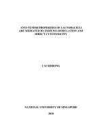
3.3. Two layer coatings
The layers were created with the same mode of overlapping the tracks, but with a different direction of
the second layer cladding: 0°, 45°, 90°. Structure of coatings is presented in figures 5–7. It is a nonequiaxed mesh, with the dendritic structure near the boundary with the substrate -, and the grain
boundaries enriched in heavy elements (Mo, W). The width of the HAZ is 300 µm, its structure is the
crushed grain ferrite-pearlite with traces of partial martensitic transformation. The iron content in the
three cases was 85%. The microhardness increased to 6000 MPa (figure 8), its dependence is more
uniform in the case with the direction of the clad layers of 0°. Since the remaining measured coating
characteristics are the same, one can conclude that the best quality of cladding is obtained when
depositing layers at 0° angle.
3
II Conference on Plasma & Laser Research and Technologies
Journal of Physics: Conference Series 747 (2016) 012064
Figure 5. Bilayer with direction of second
layer 0°.
Figure 7. Bilayer with direction of second
layer 90°.
IOP Publishing
doi:10.1088/1742-6596/747/1/012064
Figure 6. Bilayer with direction of second
layer 45°.
Figure 8. Change of microhardness over the cross
section for bilayer coatings.
4. Conclusion
Results of the study showed that the width of the cladding track and the penetration depth of filler
material in the substrate are mainly influenced by a change of the laser power, while the height of the
tracks is mostly affected by the powder feed rate. Monolayer coatings with a coefficient of tracks
overlapping 0.66 exhibit lower level of mixing between powder material and the substrate than the
coatings with coefficients 0.33 and 0.5. This is a consequence of smaller area of thermal effects on the
substrate. Bilayer coatings with the direction of the clad layers 0° are more uniform than those with a
direction angle of 45° and 90°. Differences in the ratio of mixing for the three different directions are
not observed.
Acknowledgments
This work was financial supported by the Ministry of Education and Science of Russian Federation
(unique identier PNIER RFMEFI58214X0004).
This work was also supported by Competitiveness Growth Program of the Federal Autonomous
Educational Institution of Higher Professional Education National Research Nuclear University
MEPhI (Moscow Engineering Physics Institute).
5. References
[1] Grigoryants G, Shiganov I, and Misyurov I 2006 Technological processes of laser processing
(Moscow: MGTU) (In Russian)
[2] Murzakov M, Petrovskiy V, Birukov V, Dzhumaev P, Polski V, Markushov Y, and Bykovskiy
D 2015 Phys. Procedia 71 202–206
[3] De Damborenea J and Vzquez A 1993 J. of Materials Science 28 4775–4780
[4] De Oliveira U, Ocelk V, and Hosson J D 2005 Surface and Coatings Technology 197 127–136
[5] Nenadl O, Ocelk V, Palavra A, and Hosson J T D 2014 Phys. Procedia 56 220–227
[6] Hasui A and Morigaki O 1985 Surfacing and spraying (Moscow: Mashinostroenie) (In Russian)
4