renovation of swedish single family houses to passive house standard analyses of energy savings potential
Bạn đang xem bản rút gọn của tài liệu. Xem và tải ngay bản đầy đủ của tài liệu tại đây (618.03 KB, 12 trang )
Available online at www.sciencedirect.com
ScienceDirect
Energy Procedia 96 (2016) 134 – 145
SBE16 Tallinn and Helsinki Conference; Build Green and Renovate Deep, 5-7 October 2016,
Tallinn and Helsinki
Renovation of Swedish single-family houses to passive house
standard – Analyses of energy savings potential
Tomas Ekströma,b*, Åke Blomsterbergb
b
a
NCC AB, Hyllie boulevard 10 B, Malmö 205 47, Sweden
Department of Architecture and the Built Environment, Division of Energy and Building Design, Lund University, Lund 221 00, Sweden
Abstract
A third of Sweden’s two million single-family houses were built in the period 1961-1980, and many of them are in
need of renovation. These houses have a high energy use and are in technical terms fairly homogenous. This
investigation evaluates the theoretical energy savings potential of renovating houses from this period. Four reference
houses were selected and simulated using common renovation measures. The results indicate that most of the existing
single-family housing stock will likely not be able to attain the passive house standard after renovation and using
today’s technology. This is explained by the fact that some house characteristics impose a limiting factor on the energy
renovation. Such examples are the shape, foundation and composition of the building envelope. Nevertheless, it is still
possible to drastically reduce the final energy use by approximately 65-75 %.
© 2016
2016 The
byby
Elsevier
Ltd.Ltd.
This is an open access article under the CC BY-NC-ND license
©
TheAuthors.
Authors.Published
Published
Elsevier
( />Peer-review
under responsibility of the organizing committee of the SBE16 Tallinn and Helsinki Conference.
Peer-review under responsibility of the organizing committee of the SBE16 Tallinn and Helsinki Conference.
Keywords: deep renovation, energy retrofit, detailed energy simulations, single-family houses
1. Introduction
Single-family houses built in the period 1961-1980 account for one-third of the energy use in Swedish singlefamily houses, which in turn use about 40 % of all energy in buildings [1]. These houses were built fairly homogeneous
* Corresponding author. Tel.: +46702719550.
E-mail address:
1876-6102 © 2016 The Authors. Published by Elsevier Ltd. This is an open access article under the CC BY-NC-ND license
( />Peer-review under responsibility of the organizing committee of the SBE16 Tallinn and Helsinki Conference.
doi:10.1016/j.egypro.2016.09.115
135
Tomas Ekström and Åke Blomsterberg / Energy Procedia 96 (2016) 134 – 145
in technical terms, with low levels of thermal insulation and heat recovery ventilation (HRV) is rare [2]. Thus there
are great potential to improve energy efficiency and indoor environment. A literature review showed few completed
deep renovations of single-family houses to passive house level and overall there is little written regarding the subject.
Although the initial inventory showed that it is technically possible to renovate to the level of passive house the
profitability is questionable. Many of the houses built during this period need to be renovated due to ageing [3]. This
provides an opportunity to also incorporate energy efficiency measures.
The overall aim of the research project is to increase the knowledge regarding cost effective deep renovations to
passive house level. This will be done through detailed energy simulations, life-cycle cost analysis (LCCA) and lifecycle assessment (LCA) with solutions that preserve the architectural expression of the houses. This investigation is
the starting point, focused on estimating the energy savings potential of four reference single-family houses. The
simulations were based on the Swedish passive house standard, FEBY 12, (Forum for energy-efficient buildings) [4],
as well as a comparison with the current Swedish building regulation, BBR 22 [5].
1.1. Background - Single-family houses built during the 60s and 70s
During the 1960s there was a substantial demand for new housing in Sweden. To overcome this, the “millionprogram” was initiated with the goal to construct one million dwellings during 1965-1975, including both multi- and
single-family houses. To construct this many dwellings in the short timeframe the buildings were built in a
standardized way, which makes them suitable candidates for standardized renovations. This project focus on the
single-family houses built in the period 1961-1980. From this period there are almost 714.000 single-family houses
and they account for much of the energy use in single-family houses, see Table 1. The 1973 international oil crisis
increased the costs for space heating, since many houses were heated by oil. The increased energy cost lead to a new
focus on reducing the energy use of buildings. As a result the requirements on energy efficiency increased with the
building code in 1975, SBN 75 [6], and the result can be seen in the average annual energy demand in Table 1.
Table 1. Number of houses and annual energy demand per heated floor area for space heating and domestic hot water [7, 8].
Years
Number of houses
Average annual energy demand
Units
thousands (2012)
kWh/m2/a
1961-1970
288
106
1971-1980
426
90
1961-1980
714
96
Total - 2012
2014
106
1.1.1. Constructions used in the 60s and 70s
To compile the commonly used constructions from each of the decades a literature review was performed. It also
included finding common shapes and compositions of the building envelope of houses, i.e. form and amount of
windows of the building envelope. There was some variation and influences originated both from abroad and from
Swedish building regulation. While some constructions were quite standardized, e.g. during 1961-1985 the most
common foundation was concrete slab with or without a cellar, which account for over 75 % of all m2 of foundation
in houses from this period [2]. For the concrete slabs the insulation thickness and placement varied between 70-100
mm both above and/or below the slab. For houses with crawl spaces, the joists were filled with insulation [9].
1961-1970 – To accommodate the increased production rate, many houses were built in groups with prefabricated
construction. This meant less time at the building site and with the expectation of less building problems. In the
beginning of the decade most houses were built as one story houses, alternatively adding a cellar with a recreation
room, which in the later parts changed to one-and-a-half or two story houses. Large window sections became common,
which increased the window-to-wall ratio, and two types of roof constructions were used, either ridged roof or pent
roof. The house shape was either rectangular or L-shaped with function displaced rooms; the rooms were placed based
on their use and likely connection, i.e. garage, storage, laundry room and kitchen on one side of the house and living
room and bedrooms on the other. The used faỗade material was either wood panel or bricks or a combination of both
[9, 10]. Inside the faỗade material an asphalt board was placed outside the 100 mm thick stud framework with
intermediate mineral wool insulation. On the inside of the wall a diffusion-proof plastic foil was placed to increase
the air tightness and lastly a gypsum wallboard. As an alternative construction, light-weight concrete was used with a
136
Tomas Ekström and Åke Blomsterberg / Energy Procedia 96 (2016) 134 – 145
thickness of about 200-250 mm. The roof was made out of roof trusses with intermediate mineral wool insulation of
about 125 mm. For ventilation a passive stack system was used [10].
1971-1980 - The production of houses continued to rise during this decade in part because of subsidies from the
state. The typical composition of a house from the 70s is a one-and-a-half story house with a 45° ridged roof, sharply
projecting eaves, with a balcony under the eaves on the gable side of the house. For the faỗade a common combination
was bricks on the ground floor and wood panel on the upper floor. In the areas built in groups, wooden panels were
the dominant faỗade material towards the end of the decade. The commonly used construction system was still stud
framework with intermediate thermal insulation, but the thickness of the insulation layer increased to 170-190 mm. A
plastic vapor barrier was placed on the inside of the wall to further increase the air tightness. The roof was still made
of roof trusses with intermediate insulation but the insulation thickness increased to about 245 mm of mineral wool
[9]. During this period, the ventilation system was changed from passive stack in the beginning to mechanical
ventilation with or without heat recovery ventilation as the focus on energy efficiency increased [10].
1.2. Regulation for renovation - Swedish building regulation, BBR, and passive house standard
The current Swedish building regulation, BBR 22, states that if a planned renovation is extensive the building
should fulfill the level of a newly constructed building after renovation, which includes a requirement on the specific
energy use. Included in the specific energy use is the energy needed for space heating, domestic hot water (DHW),
and property electricity, i.e. electricity used in pumps and fans needed for the functioning of the house. This energy
use is then divided by the heated floor area, Atemp. This includes the area inside the external wall that is heated to 10
°C or more, garage is always excluded. The requirements are divided into four levels, depending on climate zone, and
two categories, with and without electric heating, see Table 2. The Swedish passive house standard includes two main
requirements, specific energy use and power demand. These are divided into three climate zones, where climate zone
3 is the same as 3 and 4 in the Swedish building regulation. Also included are the passive house requirements for air
tightness and U-values for windows and glazing according to FEBY 12.
Table 2. Building regulations and passive house standard requirements [4, 5].
Specific
energy use
Climate zone
BBR 22
Passive house
BBR 22
Passive house
Power demand
Air tightness, q50
Windows and glazing
Unit
I
II
III
Without electric heating
kWh/(m²∙a), heated floor area
≤ 130
≤ 110
≤ 90
kWh/(m²∙a), heated floor area
≤ 63
≤ 59
≤ 55
Electric heating
kWh/(m²∙a), heated floor area
≤ 95
≤ 75
≤ 55
kWh/(m²∙a), heated floor area
≤ 31
≤ 29
≤ 27
Passive house requirements, other
W/m², heated floor area
≤ 19
≤ 18
≤ 17
l/(s∙m²), building envelope area
≤ 0.30 at ± 50 Pa
W/(m² ∙K)
Average U-value ≤ 0.80
IV
≤ 80
≤ 55
≤ 50
≤ 27
≤ 17
In the case in which a renovated building is not able to fulfill the requirements on specific energy use (depending
on the circumstances) or only a part of the building envelope is renovated. Then there are separate recommendations
for the thermal transmittance, U-value, for each part of the building envelope. In Table 3 the U-value for passive house
components and building regulation requirements on the different parts of the building envelope are shown.
Table 3. Minimum level of U-values when renovating according to BBR 22 [5] and passive house components.
Ui
BBR
W/(m2∙K)
Passive house components*
W/(m2∙K)
*Based on compiled completed passive house renovation projects.
URoof
0.13
0.08
UExtermal wall
0.18
0.10
UFloor
0.15
0.10
UWindow
1.2
0.80
UDoor
1.2
0.80
The Swedish building regulations also regulate the ventilation air flows allowed in residential buildings. The
minimum average outdoor air flow rate per floor area when someone is present in a room is 0.35 l/(s∙m²) and 0.10
137
Tomas Ekström and Åke Blomsterberg / Energy Procedia 96 (2016) 134 – 145
l/(s∙m²) when empty. There should also be a forced air flow- function to be able to evacuate excessive moisture and
other indoor air pollutants when needed.
1.3. Realized renovations to passive houses standard
In Sweden four completed pilot renovations of single-family houses to passive houses level were found during the
literature review. These four houses are Villa Kyoto, Villa Kanndalen, RenZERO-concept and Finnängen, see Table
4 for detailed information. For all of these a need to renovate was identified and the owner wanted to do more than
just a normal renovation. All had the goal to lower the energy use by a large margin while improving the indoor
climate by following the Swedish passive house standard, FEBY 12. Three of the houses included some kind of
renewable energy solution when renovating. The costs for completing these projects were high and with payback
periods of between 30-44 years, the cost effectiveness might be questionable. However, for the houses where the
increased value is known, this was enough to compensate for the investment cost, being in an attractive location[11].
Table 4. Completed renovation projects to passive house level in Sweden[11-14].
Finnängen
1976
Projects
Constructed
Units
year
Villa Kyoto
1977
Villa Kanndalen
1970
RenZERO
1945
Renovated
year
2014
2008
2013
2010
200
128 / 30
+300
+360
Yes, 0.9
Yes, 0.3
Yes
No
No
Yes
212 / 246*
165 / 0
(Total U-value = 0.10 W/(m²∙K))
(Total U-value = 0.08 W/(m²∙K))
Yes, 0.8
Yes, measured, 0.10-0.15
Yes
Yes
Yes
Yes
Yes
Improved
Heated floor area
Atemp
155
Energy use - before/after renovation
kWh/(m²∙a)
122 / 0
162 / 45
Walls, increased insulation
mm
+150
+150
Roof, increased insulation
mm
+500-600
+290
Windows, new W/(m²∙K)
Yes, 0.9
Yes, 0.9
Air tightness, after renovation l/(s∙m²)
Yes, 0.3
Yes, 0.3
Foundation, increased insulation
mm
+160
+100
Heat recovery ventilation
Yes
Yes
Solar collectors
Yes
Yes
PV solar cells
Yes
No
Ground source heat pump
Yes
No (district heating)
* Performed a building extension which increased the floor area of the house.
2. Methodology
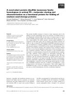
An overview of the method is shown in
Fig. 1, starting with literature reviews, from which the gathered information was compiled as input data for the
simulation models and to determine the relevant simulations. A literature review of different regulations and
certification systems used in Sweden was performed to find criteria for specific energy use, air tightness and other
parameter that impact the energy use. The literature reviews also included how typical houses were built 1961-1980,
their constructions, shapes and composition of the building envelope. This information was then used to compile
criteria, which the comparison and selection reference houses were based on. Another literature review compiled
energy renovations to passive house standard in northern Europe. This was done to find out how common this type of
renovation is, their used renovation measures, costs and achievable energy savings. This information was then used
Litterature
review
• How the houses
were built.
• Realized passive
house
renovations
• Standards and
regulations
as input to the energy simulations.
Input to
simulations
• Standards and
regulations
• Reference
houses
• Performed
passive house
renovations
components
Energy
simulations
• Reference
houses, as built
• Building
regulation level
• If newly constr.
passive house
• Step-by-step
renovation
138
Tomas Ekström and Åke Blomsterberg / Energy Procedia 96 (2016) 134 – 145
Fig. 1. Overview of method used.
The energy use and savings potential was simulated using a validated dynamic energy simulation tool, IDA Indoor
Climate and Energy 4.7 [15]. The reference houses were simulated as the houses were built to find a base case,
grounded on their original constructions. Incremental changes of the base cases were done until the result equaled a
passive house renovation e.g. improved U-values, air tightness, installations etc. based on available renovation
measures. This was done to show the variation in results from the measures depending on the house’s shape and
composition of building envelope as well as how the steps affect each other. The best-case scenario for the energy
savings potential were simulated using the models of the reference houses with constructions and installations as in a
newly constructed passive house. The building regulation level of renovation was also simulated as a comparison to
show the increased potential from a passive house renovation and what the minimum level of renovation would be.
To simulate the energy demand of the reference houses, the thermal transmittance, or U-value, for each part of the
building envelope were calculated. For foundations the calculations were done according to the standard; ISO
13370:2007 [16] and for other parts of the building envelope the standard; ISO 6946:2007 [17] was used. In Sweden
the area for which these U-values are used for are the inner surfaces of a building envelope. This means all external
connections, such as wall to wall, wall to foundation etc., are not included in the area. These connections are instead
included in the thermal bridges. The thermal bridges were assumed as an increase of the total heat losses by 25 % in
these simulations, based on the Swedish certification system Miljöbyggnad [18]. To determine the reduction of the
thermal transmittance through the foundation from the implemented renovation measure, the foundations were
simulated using the two-dimensional transient and steady-state heat transfer program HEAT2 [19]. The results were
then used in the total building energy simulation performed in IDA ICE.
3. Reference houses
3.1. Choice of reference houses
The objective was to find houses that cover as many of the constructions and architectural designs that were used
in the 1960s and 1970s. First, it was decided that four houses were enough to balance the amount of simulations
needed and at the same time get variation between the houses. Next, the locations were chosen with the aim to spread
them across Sweden to try to represent the whole country. This was based on city size, location and the amount of
single-family houses that were built there in this time period. The chosen locations are Malmö, Göteborg, Stockholm
and Umeå, since in these cities over 200.000 (roughly 30 %) single-family houses were built during this time period.
With the increased focus on energy efficiency in the building regulation from 1975 the goal was to find houses built
both before and after this regulation took effect.
Table 5. Criteria and reference houses.
Location
Construction year
Ridged
Roof
Pent
Rectangular
Shape
Function displaced
Wood panel
Facade Combination of bricks and wood
Plaster
Wooden studs
Constr. Concrete
Light weight concrete
One floor
Floors One and a half or two floors
Cellar
Oil
Energy
Electricity
source
District heating
Passive stack ventilation
Vent.
Mechanical exhaust ventilation
Malmư
1965
Stockholm
1965
X
X
X
Gưteborg
1961
X
X
Umể
1977
X
X
X
X
X
X
X
X
X
X
X
X
X
X
X
X
X
X
X
X
X
X
X
139
Tomas Ekström and Åke Blomsterberg / Energy Procedia 96 (2016) 134 – 145
HRV
X
Based on the literature review a compilation of criteria was done, see Table 5. For each location four houses of
different types were picked to be compared. Their drawings and descriptions were collected from the city-planning
office. Out of these 16 houses, four was chosen, see Table 5.
3.2. Description of reference houses
The four chosen reference houses are presented in Table 6 with basic information and an illustration of the building
model from IDA ICE 4.7. The building models are based on available drawings and descriptions and the models were
made with one zone for each room in the houses.
Table 6. Basic data for reference house, Malmư, Gưteborg, Stockholm and Umể.
Location:
Malmư
Year built:
1965
No. of floors:
1 + Cellar
Atemp:
230 m2
Passive stack ventilation
Ventilation:
Description: Function displaced one story house with cellar and a pent roof,
light weight concrete walls and a concrete slab foundation. Garage attached.
Location:
Göteborg
Year built:
1961
No. of floors:
1
Atemp:
140 m2
Passive stack ventilation
Ventilation:
Description: Rectangular one story house with a pent roof, sandwich concrete
walls and a concrete slab foundation.
Location:
Stockholm
Year built:
1965
No. of floors:
2
Atemp:
163 m2
Passive stack ventilation
Ventilation:
Description: Rectangular two story house with a ridged roof, light weight
concrete walls and a concrete slab foundation. Garage inside building envelope.
Location:
Umể
Year built:
1977
No. of floors:
1½
Atemp:
142 m2
Balanced ventilation with heat recovery
Ventilation:
Description: Rectangular one-and-a-half story house with a ridged roof, wood
frame structure walls insulated with mineral wool and a concrete slab
foundation.
3.3. Building envelope of reference houses – before renovation
Based on the available drawings and descriptions of the reference houses, the material types and thicknesses of the
building envelope were determined, see Table 7. All four of the reference houses have a concrete slab foundation but
the house in Malmö also has a cellar. The insulation type and thickness of the foundation is known for the houses in
Malmö and Göteborg, but not for the houses in Stockholm and Umeå. When not known, the insulation thickness was
estimated based on the building regulation current at the time of construction [20] [21] [6].
140
Tomas Ekström and Åke Blomsterberg / Energy Procedia 96 (2016) 134 – 145
Table 7. Reference houses building envelope, material type and thickness.
Göteborg
Stockholm
Sandwich element: 60 mm
concrete + 100 mm min.
Exterior walls
Render + 250 mm light
Render + 250 mm light
(inside –
wool + 60 mm concrete.
outside)
concrete + render
Light frame constr.: 100 mm
concrete + render
min. wool / stud frame +
9mm gypsum board
Concrete roof: 130 mm min.
Roof truss 45ൈ195 c/c
Roof truss 45ൈ195 c/c
wool + 220 mm concrete.
Roof
1200 mm +
1200 mm + 200 mm saw
(top – bottom)
Truss roof: Roof truss + 150
(80 + 30) mm min. wool
dust + 25 mm min. wool
mm min. wool
Total thickness 250 mm,
Total thickness 250 mm,
Total thickness 250 mm,
70 mm insulation, type
unknown insulation,
100 mm min. wool/stud
Exterior floors
assumed to 100 mm + ~150
(top – bottom)
unknown + ~180 mm
frame + ~150 mm
concrete
concrete*
mm concrete
* Estimation of insulation thickness based on regulation in force at time of construction.
Location
Malmư
Umể
10 mm plywood + 180 mm
min. wool/stud frame (145 +
70)ൈ34 mm + 13mm gypsum
board
Roof truss 45ൈ195 c/c 1200
mm + 300 mm min. wool
Total thickness 250 mm,
unknown insulation, assumed
to 100 mm + ~150 mm
concrete*
Based on the gathered information the U-values were calculated for the reference houses. Regarding windows and
external doors, the gathered information was not enough to determine the U-values. Instead they were estimated based
on information of used U-values from the time period. In 1967, the then new building regulation, SBN 1967 [21],
required the U-values for windows to be 2.7 W/(m2∙K) or lower to fulfill the regulations. With the release of a new
regulation in 1975, SBN 1975 [6], the required U-value for windows improved to 2.0 W/(m2∙K) or lower. For the three
reference houses built 1961-1965 there was no regulation in force regarding U-values for windows. So the estimation
was based on the closest alternative, SBN 1967, to 2.8 W/(m2∙K). For external doors there were no regulation regarding
U-values, so they were estimated to 1.5 W/(m2∙K). See Table 8, for a summary of the calculated and estimated Uvalues for the reference houses.
Table 8. Building envelope U-values for reference houses before renovation.
U-value
W/(m²∙K)
Building envelope
Location
Roof
Foundation, floor against ground
Foundation, floor against air
Cellar wall
Wall
Windows
Doors
Addition for thermal bridges:
Malmö
0.36
0.32
0.54
0.54
2.8
1.5
Reference houses - Base case
Gưteborg
Stockholm
0.26
0.31
0.23
0.23
0.33
0.33
0.54
2.8
2.8
1.5
1.5
25%
Umể
0.15
0.23
0.23
2.0
1.5
3.4. The ratio between the building envelope area and the heated floor area
In Table 9 the ratio between the area of different parts of the building envelope and the heated floor area of the
reference houses are presented. The presented ratios are between the total building envelope area and the heated floor
area and window area to floor and to faỗade area. Higher ratios indicate a higher need for space heating, since the
building envelope is larger or have a higher thermal transmittance. By analyzing the ratio of a house some initial
assumptions can be made, e.g. by comparing the ratio for the reference houses. By comparing the ratios, it is likely
that the houses in Göteborg and Stockholm will need more effective renovation measures to reach the same level of
final energy use as the houses in Malmư and Umể.
Table 9. The ratio between the building envelope area and the heated floor area.
Reference house
Ratio
Abuilding envelope/ Atemp
Awindow / Atemp
Awindow / Afacade
Malmư
Gưteborg
Stockholm
Umể
207%
22%
20%
308%
28%
26%
232%
20%
17%
213%
13%
13%
Tomas Ekström and Åke Blomsterberg / Energy Procedia 96 (2016) 134 – 145
141
3.5. Input data for simulation
To simulate the final energy use all input data must be determined. For energy simulations, work has been
performed to standardize the input data in Sweden. This is compiled in SVEBY, Standardize and verify energy
performance for buildings [22], and it gives default values for internal heating loads and other input such as indoor
temperature, forced ventilation air flows in kitchen, solar shading, domestic hot water use, household electricity use,
number of inhabitants in the houses and their presence [22]. Based on SVEBY the simulated annual DHW energy use
per heated floor area was 20 kWh/(m²∙a) and the simulated house hold electricity was 30 kWh/(m²∙a). From FEBY 12
input regarding the airing and regulating losses for the heating system was gathered.
For the reference houses with passive stack ventilation the actual ventilation air flow is unknown and some
assumptions regarding the air flows were needed. As part of the BETSI evaluation of the Swedish building stock the
air flow in naturally ventilated single-family houses was measured, using the standard ISO 16000-8 [23], to a mean
flow per heated floor area equal to about 0.23 l/(s∙m²) with a normal ceiling height of 2.4 m. This includes the air flow
both from infiltration and from the ventilation air gaps used for the passive stack ventilation [10]. This means that the
houses with passive stack ventilation most likely do not fulfill the current building regulation requirements regarding
minimum ventilation air flow. Thus, the energy demand will also be lower than if the regulation was fulfilled. The
reference house in Umeå was built with a mechanical heat recovery ventilation system with a plate heat exchanger.
The exact specifications are not known, so the dry heat recovery efficiency according to SS-EN 308:1997 [24] was
assumed to be 50 % and the specific fan power, SFP, was assumed to be 2.0 kW/(m3/s).
3.6. Step-by-step simulations
To determine the impact on the energy demand of different renovation measures, a step-by-step simulation was
performed. This was used to find the energy savings potential for this type of deep renovation project and indicate if
it is possible to achieve the Swedish passive house level. This evaluation does not include the effects of the energy
sources or heating systems, which will be evaluated in future work. The renovation measures are based on commonly
used renovation measures in completed passive house renovations from the literature review. The order of the steps
has been chosen based on how common the measures were, relative cost based on the completed renovations, how
they affect each other and depending on which energy item they effect. The different measures are divided into nine
steps, where step 5 and 6 also are divided into parts. The measures for each step are described below, mainly in specific
values, e.g. U-values or ventilation air flows. All steps include the measures from the step before, i.e. Step 2:
Windows/doors, also includes the measures from Step 1: Roof. The measures that improve the building envelope also
impact the air tightness, but by how much are hard to determine. So the improvements to air tightness were saved for
Step 5 – Air tightness. This means the energy savings from Step 1-4 is underestimated. In this evaluation it does not
matter, since all steps need to be performed to reach the level of quality and energy demand that is the goal of the
project. The used values are chosen based on real constructions and solutions that are achievable today when
renovating and found in completed passive house renovations. The exact solution to reach those specific values are
not included in this paper, but will be evaluated in future work.
Step 1: Roof - Increasing the total insulation thickness equal to a U-value of 0.08 W/(m2∙K).
Step 2: Windows & door – New windows and doors, with a U-value of 0.80 W/(m2∙K).
Step 3: Foundation – Due to the original foundations for the reference houses all being concrete slabs, the added
insulation was placed outside the slab, as illustrated in Fig. 2.
Step 4: External walls - Increasing the total insulation thickness equal to a U-value of 0.10 W/(m2∙K).
142
Tomas Ekström and Åke Blomsterberg / Energy Procedia 96 (2016) 134 – 145
Fig. 2. Illustration of the renovation measure for the foundation, exact solution depends on the original construction of the reference house.
Step 5, part I and II: Air tightness – Passive stack ventilation and building regulation air flows – The air
tightness of the building envelope was improved to 0.3 l/(s∙m2). Simulating the improved air tightness was divided
into two parts for the houses with passive stack ventilation; part I keeping the existing ventilation and part II with
mechanical exhaust ventilation without heat recovery. Part I will reduce the total ventilation air flow of the passive
stack ventilated houses, to a level a lot lower than before and even further from the regulation level, which is a common
problem in old houses with this ventilation system. This will also lower the simulated energy demand much lower
than what would be a realistic level, since the houses will not fulfill the building regulation, indicated by the simulation
of part II. The part II was not needed for the house in Umeå, which already has HRV.
Part I: The houses are simulated with an air tightness of 0.3 l/(s∙m2) and their existing ventilation system, either
passive stack or mechanical.
Part II: A mechanical exhaust air ventilation without heat recovery was added to fulfill the building regulation
ventilation air flow per floor area of 0.35 l/(s∙m2). The SFP was assumed to be 0.6 kW/(m3/s), which is the highest
allowed for this type of ventilation in BBR 22 [5].
Step 6, part I and II: Heat recovery ventilation – A balanced ventilation system with heat recovery was installed
for all reference houses. The dry temperature efficiency was assumed to be 80 % and the SFP was assumed to be 1.5
kW/(m3/s). Supply air temperature after the heat recovery was heated to a temperature of 19 °C so the air temperature
is below room temperature to ensure good air circulation. The HRV measure was divided into part I with constant air
volume (CAV) and part II with demand controlled ventilation (DCV).
Part I: The CAV ventilation air flow per floor area was 0.35 l/(s∙m2) based on the building regulation.
Part II: For the DCV the air flow when someone is present in the house was 0.35 l/(s∙m2), but when empty the
DCV reduces the air flow to 0.10 l/(s∙m2).
Step 7: Electronic controlled thermostats - For the base case it was assumed that standard indoor temperature
mechanical controlled thermostats were used. After renovation the indoor temperature electronic controlled
thermostats was used, with the aim of decreasing the regulation losses from 11 % to 7 % according to FEBY 12 [4].
Step 8: Circulation pump - The circulation pumps in the base case were assumed to be the original pump from
when the houses were built. The pumps was exchanged to new circulation pumps that are more efficient and that also
has a pump stop, which will turn the pump off if there is no space heat demand [25]. The period that the pump is
turned off will also increase because of the fact that the other renovation measures lower the space heat demand of the
houses. The hours are estimated based on the heating season from the energy simulations.
Step 9: Indoor temperature variation - Indoor temperature variation was used, reducing the indoor temperature
from the standard 21 °C to 18 °C when no one is home and when the inhabitants are asleep. This was assumed to be
between 08:00 and 16:00 on weekdays and, at night, 23:00-06:00 on weekdays and 00:00-08:00 at weekends. This
was done with a central controlled thermostat.
143
Tomas Ekström and Åke Blomsterberg / Energy Procedia 96 (2016) 134 – 145
3.7. Comparison calculations
For comparison, two alternatives were simulated for the reference houses; the first was the minimum level of
renovation with measures based on fulfilling the building regulations for new construction. Secondly the best-case
scenario where the houses were simulated as if newly constructed passive houses, see Table 3 for U-values.
The “building regulation level renovation” comparison was simulated with the U-values fulfilling the regulation
and with the building envelope air tightness improved to 0.3 l/(s∙m2). The circulation pump was exchanged and a
mechanical exhaust ventilation system without heat exchange was installed with a ventilation air flow of 0.35 l/(s∙m2)
per floor area. The SFP was assumed to be 0.6 kW/(m3/s). The foundation was not improved due to the problem with
fulfilling the specific U-value requirement; all other input remained as in the base case.
The “if newly constructed passive house” comparison had the same input as step 9 in the step-by-step renovations,
but instead of the measures for improving the foundation in step 3 a foundation equal to a new passive house
foundation was used, with an U-value of 0.90 W/(m2∙K).
4. Results
The simulated results are presented in Table 10 as final energy use, which includes space heating, DHW and
property electricity. These results are presented to show the potential for different renovation measures and their
respective energy savings potential. The results are presented per reference house, starting with the base case and then
adding the steps 1-9 and ending with the total reduction from all measures. Lastly, the simulated comparisons
“building regulation level renovation” and “if newly constructed passive house” as well as the passive house
requirements from FEBY 12 are presented. The results are divided into annual final energy use per heated floor area
and the reduction in percentage per step compared to the base case.
Compar
ison
Step-by-step renovation
Info.
Table 10. Resulting annual final energy use per heated floor area and reduction vs. base case from step-by-step and comparison simulations.
Reference house
Malmö
Heated floor area, Atemp,m2
230
Units
kWh/(m²∙a) %
Baseline case
160 0
Step 1: Roof
137 -14
Step 2: Windows & doors
106 -34
Step 3: Foundation
104 -35
Step 4: External wall
62 -61
Step 5, part I: Air leakage
47 -70
Step 5, part II: Air leakage
97 -39
Step 6, part I: CAV
60 -63
Step 6, part II: DCV
56 -65
Step 7: Electrical thermostat
55 -66
Step 8: Circulation pump
50 -68
Step 9: Indoor temperature variation
49 -69
Total reduction
-111 -69
Building regulation level renovation
116 -25
If newly constructed passive house
42 -74
Passive house requirement
≤ 55 -
Göteborg
140
kWh/(m²∙a) %
229 0
205 -10
124 -46
112 -51
89 -61
63 -72
119 -48
77 -67
72 -68
71 -69
64 -72
61 -73
-168 -73
158 -31
55 -76
≤ 55 -
Stockholm
163
kWh/(m²∙a) %
209 0
203 -3
144 -31
139 -34
84 -60
66 -68
129 -38
80 -62
76 -64
74 -65
68 -68
66 -69
-143 -69
166 -21
57 -73
≤ 55 -
Umeå
142
kWh/(m²∙a) %
187 0
181 -3
137 -27
133 -29
115 -38
104 -44
- 81 -57
76 -59
74 -60
67 -64
63 -66
-124 -66
133 -28
55 -70
≤ 63 -
5. Conclusions & discussion
This study show that there is great energy savings potential for all reference houses while using, by today’s
standard, common renovation measures and ignoring costs at this stage. The results from the simulations show a
reduction of the final energy use by 65-75% for all four reference houses, presented in Table 10. Still, the step-bystep simulations show that only the reference houses in Malmư and Umể were able to reach the passive house level
when renovating, since today there is no economically feasible way to improve the concrete foundation to the same
level as for a newly constructed passive house. Furthermore, the comparison simulations show that even while
144
Tomas Ekström and Åke Blomsterberg / Energy Procedia 96 (2016) 134 – 145
assuming the houses as “if newly constructed passive house”, the shape and composition of the building envelope
have such a large impact that one reference house, Stockholm, with a small margin does not fulfill the passive house
requirements and another reference house, Göteborg, is just at the level. While it might be possible to improve all
steps even further to try and reach the passive house level this will likely not be a cost effective solution since none
of the realized passive house renovations have tried to do so. These results points out an important limitation when
renovating single-family houses to passive house level, not all parts can be improved to passive house level. Instead
it is likely that the next step should be some kind of renewable energy solution, since the space heating demand was
lowered by 75-80% in these simulations while the domestic hot water use was assumed not to change. This means
that out of the total annual final energy use of 49-66 kWh/m2 after a complete renovation, 20 kWh/m2 are from
domestic hot water. Thus a renewable energy solution that decreases the need for bought energy for heating the
domestic hot water could have a large impact on the end results.
Compared to the statistical specific energy use for existing houses presented in Table 1 the simulated final energy
use for the base cases presented in the results in Table 10 were higher. One reason for this discrepancy is that the
statistical energy use is an average for all houses from the respective time period and in their current state in 2013,
including any renovations and improvements performed since their construction. Determining how houses were built
during this period showed many possible variations which also could indicate a great variation in the energy use. The
four reference houses fulfilled the building code requirements during the period of construction and it is known that
many houses today are not extensively energy renovated, so this is likely not the reason for the difference. But a
common measure in Swedish single-family houses is the installation of some type of heat pump, which reduces the
bought energy compared to the final energy. This is likely the main reason for the difference, since the simulated final
energy use does not take into account the energy source, i.e. if a heat pump is installed. Thus the exact level of specific
energy use the houses could reach by implementing these renovation measures depends on the houses’ specific
conditions. Regardless of how accurately the four reference houses represent the total housing stock, based on these
results, it is likely most houses could be renovated to reduce the final energy use by at least 60 % if the evaluated
measures in this study were implemented, unless other limitations are valid such as cultural heritage protection.
Compared with the simulated “building regulation level renovation” for new construction the step-by-step
renovation reduces the final energy use by more than twice as much, a 20-30 % reduction compared to 65-75 %. The
step-by-step renovation for all reference houses fulfills the building regulation requirement regarding specific energy
use for newly constructed houses, which is a requirement when performing extensive renovations. Renovating
according to the building regulation using only the fixed U-values does not fulfil the building regulation requirements
for specific energy use.
Regarding the step-by-step renovations, there are some steps that show some interesting results. In Step 5, part II
the impact of the ventilation air flow on the final energy use of a house is shown, increasing the energy use by almost
100 % relative to part I. This highlights one of the problems with performing deep renovations on houses that originally
had passive stack ventilation. When the air quality is ensured by mechanical ventilation according to the regulatory
air flow, it could also increase the energy use and decrease the cost effectiveness of the renovation measures,
depending on the original air flow. This also indicates the problem that naturally ventilated houses usually have too
low ventilation air flow compared to today’s building regulation, especially in the period from March to October, but
this can also be true in winter. Up until step 9 all steps have been an improvement of the indoor climate by reducing
draught and temperature differences, which can improve the operative temperature, in a room while also lowering the
energy use. The measures in step 9 won’t worsen the indoor climate if done right, but there is always some risk that
the lowered indoor temperature is sensed as too cold by the inhabitant.
6. Future work
As a continuation of this work a sensitivity analysis will be performed to determine uncertainties arising from the
renovation measures used in this study and which parameter that impact the results the most. This will be done by
varying the input data used for different parameter in the simulations, e.g. how varying the internal gains or air tightness
Tomas Ekström and Åke Blomsterberg / Energy Procedia 96 (2016) 134 – 145
impacts the energy demand of the houses. The next step will be to compile variations of the simulated renovation
measures and estimate the associated costs of implementing them. These alternatives will be evaluated in future work
by LCCA and LCA, and will also include renewable energy solutions and thermal comfort simulations, to try and find
cost-effective combinations of renovation measures to reach the Swedish passive house standard.
Acknowledgements
The project is funded by the Development Fund of the Swedish Construction Industry (SBUF), the Swedish Energy
Agency and NCC AB.
References
[1] Swedish Energy Agency, Summary of energy statistics for dwellings and non-residential premises for 2014. 2015.
[2] Boverket, Energi i bebyggelsen - tekniska egenskaper och beräkningar, resultat från projektet BETSI. 2010, Boverket.
[3] Boverket, Teknisk status i den svenska bebyggelsen – resultat från projektet BETSI. 2010.
[4] Martin Erlandsson, S.R., Eje Sandberg, Åke Blomsterberg, Hans Eek, Olof Ingulf, Kravspecifikation FEBY12 - Bostäder. 2012, Sveriges
Centrum för Nollenergihus.
[5] Boverket, BBR 22 - BFS 2011:6 t.o.m. BFS 2015:3 konsoliderad, in Swedish building regulation, Boverket, Editor. 2015, Boverket.
[6] Planverk, S., Svensk Bygg Norm - SBN 1975, utg 3, in Swedish building regulation, S. Planverk, Editor. 1975.
[7] Sweden, S., Number of dwellings by type of building 1990-2013. 2015, Statistics Sweden.
[8] Swedish Energy Agency, Energy statistics for one- and two-dwelling buildings in 2014 ES 2015:06. 2015.
[9] Cecilia Björk, L.N., Laila Reppen, , Så byggdes villan - Svensk villaarkitektur från 1890 till 2010. Vol. 2. 2009.
[10] Boverket, Så mår våra hus - Redovisning av regeringsuppdrag beträffande byggnaders tekniska utformning m.m. 2009.
[11] Paroc, PAROC renZERO – Energy renovation to near-zero the first total concept in Sweden (in Swedish). 2014.
[12] Orvarson, E. Villa Kyoto. [cited 2015 2015-04-01]; Available from: />[13] Isover. Villa Kanndalen - 70-talshus renoveras till lågenergistandard. 2008
[cited 2016 2016-03-23]; Available from:
/>[14] Molin, A. Plusenergihus Finnängen. 2012 [cited 2016 2016-04-14]; Available from: />[15] EQUA, IDA Indoor Climate and Energy 2016, EQUA Simulation AB. p. Detailed and dynamic multi-zone simulation application for study
of thermal indoor climate as well as the energy consumption of the entire building.
[16] Swedish Standards Institute, SS-EN ISO 13370:2007 - Thermal performance of buildings – Heat transfer via the ground – Calculation methods
(ISO 13370:2007), in ISO standard. 2008.
[17] Swedish Standards Institute, SS-EN ISO 6946:2007 - Building components and building elements – Thermal resistance and thermal
transmittance – Calculation method, in ISO standard. 2008.
[18] SGBC, Miljöbyggnad 2.2 - Bedömningskriterier för befintliga byggnader. 2014, Sweden Green Building Council.
[19] BLOCON, HEAT 2. 2016, BLOCON SWEDEN: p. HEAT2 is a PC-program for twodimensional transient and steady-state heat transfer. .
[20] Kungliga Byggnadsstyrelsen, BABS-1960 - Byggnadsstadgan 1960, in Swedish building regulation. 1960.
[21] Statens Planverk, Svensk Bygg Norm - SBN 1967, in Swedish building regulation. 1967.
[22] Levin, P., Sveby - Branschstandard för energi i byggnader. 2012.
[23] SIS/TK 423/AG 1, I., ISO 16000-8:2007, IDT - Inomhusluft - Del 8; Bestämning av luftens lokala medelåldrar i byggnader för karaktärisering
av
ventilationsförhållandena.
2008,
Svensk
standard:
/>[24] Industriteknik, S.-. SS-EN 308:1997, in Heat exchangers - Test procedures for establishing performance of air to air and flue gases heat
recovery devices. 1997, SIS - Industriteknik.
[25] Swedish Energy Agency, Circulation Pumps - Water based heating. 2014; Available from: />
145