AT&T Wireless IP Network Security pptx
Bạn đang xem bản rút gọn của tài liệu. Xem và tải ngay bản đầy đủ của tài liệu tại đây (217.84 KB, 28 trang )
1
AT&T Wireless IP
Network Security
AT&T WIRELESS IP SERVICE
WHITE PAPER
2
AT&T Wireless IP Network Security
AT&T Wireless Services, Inc.
Revision 1.0, 10/99
© 1999 AT&T Wireless Services, Inc.
All rights reserved.
Copyright Notice This work is protected by the copyright laws of the United States and is proprietary to AT&T Wireless
Services, Incorporated. Disclosure, copying, reproduction, merger, translation, modification, enhancement or use by anyone
other than authorized employees or licensees of AT&T Wireless Services, without prior consent of AT&T Wireless Services, is
prohibited. All trademarks or registered trademarks are the property of their respective owners.
For questions about this document, please contact:
Bonnie Beeman
Manager CDPD Product Development
AT&T Wireless Services, Inc.
PO Box 97061-6702
Redmond, WA 98073
(425) 580-6702
Peter Rysavy
Primary Contributing Writer
CDPD Product Development
AT&T Wireless Services, Inc.
3
AT&T Wireless IP Network Security
Contents
1. Introduction 4
1.1. The Need For Security 4
1.2. Defining and Implementing an Effective Security Policy 5
2. AT&T Wireless IP Network Security Overview 5
2.1. AT&T Wireless IP Network Architecture 6
2.2. Network Interfaces 8
3. Airlink Interface 8
4. IP Address Management 9
5. External Network Interface 9
5.1. Frame Relay Connections 9
5.2. Firewalls for Frame Relay 9
5.3. Redundant Connections 10
6. Internet Interface 10
7. Intercarrier Interface 10
8. PocketNet
®
Compatible Phone 11
9. Wireless Application Protocol (WAP) 12
10. Virtual Private Network (VPN) Solutions 13
10.1. AT&T VPN Solution 14
10.2. Customer VPN Solution 15
11. Enhanced Data Rates for GSM Evolution (EDGE) 15
Appendix A: Data-Security Technologies and Standards 17
Appendix B: CDPD System Specification Security Requirements 21
Appendix C: Acronym List 28
4
1. Introduction
This document provides a high-level description of the issues associated with wireless data security. It
addresses security concerns and identifies standard and optional solutions to ensure that organizational
data security is safe and reliable for AT&T Wireless IP service customers. This document explains the
security features of the AT&T Wireless IP network and clarifies how these features would best augment a
customer’s security policy to achieve a complete security solution. It is intended for potential users of
wireless data services who may have concerns about the security of their data but who may not be
familiar with the various security features and options of the wireless IP network and other associated
wired network connections.
This document is a product of AT&T Wireless Services, Inc. As security issues change, so will this document.
1.1. The Need For Security
Many of the ways we communicate today are via relatively insecure channels. For instance, we regularly
use phone lines for voice and modem communication that can easily be tapped. By contrast, AT&T
Wireless IP service offers significant security features that resist attack by a passive airlink eavesdropper
or a malicious network user. But by themselves, these security features do not necessarily provide all the
security that a customer may require.
Ensuring network security in the modern world is driven by the need to:
• Maintain the integrity of highly sensitive information in a distributed network environment.
• Prevent fraud in the electronic commerce and banking industry.
• Provide necessary information to defense and law enforcement agencies.
• Service critical information warehouses and applications.
However, securing an organization or company’s data network and its various interconnections presents
a challenge, but one that may be accommodated through deployment of security technologies available
today. It should be noted that implementing a security policy requires careful analysis. An organization
must understand the technological considerations of network security and must balance the cost of
security measures against its potential benefits. While security measures prevent and/or reduce the risk
of unauthorized access, security may also delay work by creating additional processing overhead. Security
measures may also create expensive administrative and educational overhead, as well as use significant
computing resources that require dedicated hardware.
For corporate facilities, physical security is usually based on security guards, card-key entry systems,
closed-circuit television, and off-limits areas. With these security measures in place, an organization can
feel confident that within their physical facilities, assets are protected, and high user productivity is
maintained. To extend this physical security model into the virtual world of internal and external
networking and Internet access, organizations must decide where to strike a balance between access,
productivity, and security measures that may be perceived as restrictive by users of the organization’s
network.
The primary goal of a good security policy and design is to resolve security requirements while adding as
few restrictions as possible from the network user’s perspective. It is of utmost importance for organizations
to understand what they want to protect, what level of access is needed, and how these two considerations
work together. For example, an organization may need strict protection on its accounting databases, but may
need only limited protection on its internal mailing list. The important point is that any decision to invest
in security systems must answer two questions:
• How valuable is the information that is being protected?
• What is the perceived level of threat to the information?
Extending a corporate security policy to include wireless data networks requires an understanding of the
security being utilized by the existing wireless data technology, as well as the security provided by
networks to which the wireless network provides access.
5
1.2. Defining and Implementing an Effective Security Policy
An effective security policy is best defined after thorough analysis of an organization’s unique security
issues. These security issues must be resolved in order to implement an effective security policy:
• Know the company or organization’s assets. An organization needs to understand what they
want to protect and what level of access is appropriate. An organization may discover that certain
parts of the infrastructure can be left open because there is little cost involved if these parts are
somehow compromised.
• Balance the cost of security. Security costs must be in proportion to the actual dangers; otherwise,
the cost could be unnecessarily burdensome to the entire organization it is also important to
understand how technological considerations relate to cost. For example, an organization may not
have the capacity or resources to replace legacy systems that may not be supported by their original
vendors. In this case, it may not be possible to implement new technical options such as encryption.
• Identify security assumptions. It is inherently dangerous for an organization to assume that its
network is not compromised, that intruders are not very knowledgeable, that they are using standard
software, or that a locked room is safe. It is important to examine and justify assumptions; any hidden
assumption is a potential security risk.
• Allow for human factors. If security measures interfere with essential uses of the system, users
will sometimes resist and even circumvent them. For example, because automatically generated
“nonsense” passwords can be difficult to remember, users often write them on desktops, on the
undersides of keyboards, or on other surfaces which can easily be seen by others, and in this way
render a password protection measure wholly self-defeating from a security standpoint. In order to
achieve compliance, users must understand and accept the need for security and, more importantly,
security measures must be reasonable, allowing users to get their work done.
In order to detect security problems, an organization must understand how a system normally functions,
how devices are normally used, and what typical behavior to expect. Detecting unusual behavior, tracking
this behavior, and logging unusual events, can help catch intruders before they can damage the system.
An organization must create barriers within their system so that if an intruder accesses one part of a
system, they would not automatically have access to the rest of the system. Partitioning should be
considered in order to provide as much protection as necessary for network components. Although
maintaining a high level of security on the entire infrastructure is difficult, it is often possible to do so for
smaller, sensitive components.
Almost any change made to a system can affect security. This is especially true when new services are
created. System administrators, programmers, and users should consider the security implications of
every potential system change. Understanding the security implications of a change takes practice; it
requires lateral thinking and a willingness to explore every way that a service could potentially be
manipulated. Another goal of a good security design and policy is to create an environment that is not
susceptible to every minor system change.
It is not the intent of this document to be a complete tutorial on network security. There are many good
books and Internet-hosted information on the subject. But for reference, some general information on
network security is provided in “Appendix A: Data Security Technologies.”
2. AT&T Wireless IP Network Security Overview
The AT&T Wireless IP network was designed with security in mind. It includes an authentication proto-
col that resists attack by a passive airlink eavesdropper, the most common fraud method used on the
analog cellular voice system, Advanced Mobile Phone System (AMPS). By contrast, AT&T Wireless IP
service is based upon Cellular Digital Packet Data (CDPD) technology. A consortium of industry leaders
developed the CDPD System Specification. AT&T Wireless IP service refers to the underlying CDPD
network, as well as additional features that AT&T has added, such as means for connecting to customer
networks and security provisions. Other cellular carriers also have CDPD services, but the overall set of
features other carriers offer are not necessarily the same as services offered by AT&T Wireless IP
service. The name of other carrier’s service may also be different. AT&T Wireless IP service is an evolving
6
packet data service that will be fundamentally enhanced in the future.
One of the most critical aspects of the CDPD System Specification is its definition of security requirements.
The specification includes encryption of the user’s data and concealment of the user’s identity over
the airlink.
Additionally, CDPD offers some of the most advanced network security services among the wireless
wide-area networks that exist today. Key benefits of CDPD security include:
• Only legitimate mobile systems can connect to the network.
• All unicast user data is transmitted over the airlink in encrypted form.
• Encryption keys between the mobile system and the CDPD network change each time the mobile
system connects to CDPD. This means that even if an intruder were able to determine the key for
one session, the key would be useless for subsequent sessions.
An Internet Protocol (IP) address, whether for a mobile system or a fixed-end system, is never transmitted “in
the clear” (i.e., in an unencrypted format) over the airlink. This is an important security measure because
many firewalls are designed to route traffic only to and from particular IP addresses. IP address encryption
helps prevent intruders from obtaining the address of network components by eavesdropping on the
airlink and then attacking a corporate network via connected networks such as the Internet. AT&T
Wireless Services (AWS) has implemented security features in addition to the features provided by the
CDPD technology. The security aspects of these components and interfaces of the AT&T Wireless IP
network, as well as its connections to other networks, are summarized in the following sections entitled
“AT&T Wireless IP Network Architecture” and “Network Interfaces.” Subsequent sections of this
document elaborate on select topics introduced in these summaries.
2.1. AT&T Wireless IP Network Architecture
The AT&T Wireless IP network consists of specific components. To understand the security aspects of
the network, it helps to understand the basic network components between which data transfer occurs.
But it is not sufficient to look at the AT&T Wireless IP network alone. It is important to consider how
the AT&T Wireless IP network connects to other networks, such as customer networks and the Internet.
It is also important to consider how the AT&T Wireless IP network interconnects with wireless IP
networks from other carriers. The primary components and interfaces of the AT&T Wireless IP network
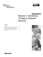
are shown in Figure 1.
Figure 1: Components and interfaces of the AT&T Wireless IP network
Frame
Relay
Static Routing
PVC
Corporate
WAN/LAN
IS, Firewall
F-ES
RDBMS
AT&T Wireless IP Service
Internet
IS, Firewall
IS, Firewall
AirLink Interface
VPN End-to-End Encryption*
IS, Firewall
User Authentication*
Corporate
LAN or DMZ
IS, Firewall
F-ES
Other CDPD
Service Provider
CDPD RSA RC4 Encryption
CDPD Authentication
MDBS
MD-IS
M-ES
Internet
Interface
VPN User Authentication*
External
Interface
Intercarrier
Interface
M-ES Mobile-End System
MD-IS Mobile Data Intermediate System
MDBS Mobile Data Base Station
F-ES Fixed-End System
IS Intermediate System
WAN Wide Area Network
RDBMS Relational Database Management System
DMZ Demilitarized Zone
Customers can enhance their level of security by adding
barriers of encryption, authorization and firewalls.
Wireless IP Enhanced Security already available
*Optional security administered by customer
7
To understand security associated with using the AT& T Wireless IP network, first examine the
components of the overall network:
• Mobile End System (M-ES): This is the wireless computing device used to connect to the CDPD
network. An M-ES usually consists of a laptop computer connected to a CDPD compatible modem
or a PocketNet
®
Compatible Phone. Since an M-ES can potentially be stolen, it is best to employ a
security solution that does not rely solely on the M-ES hardware. For any sensitive information that
can be accessed by applications on the M-ES, the user should be required to provide a password or
be required to use a hardware token. A network manager should also be aware that an M-ES uses a
fixed IP address. There are two types of IP addresses, secure and non-secure. These are described in
the section entitled “IP Address Management.” Note also that the PocketNet compatible phone
service employs architecture with separate security protocols. These protocols are detailed in the
section entitled “PocketNet
®
compatible phone.”
• Mobile Data Base Station (MDBS): This is the stationary network component responsible for
interactions across the airlink interface. A MDBS is located in each cell site, and its primary role is to
relay data between the M-ES and the MD-IS. The MDBS acts as a relay between M-ES and the MD-IS
and does not employ any networking security provisions.
• Mobile Data Intermediate System (MD-IS): This is the component responsible for most
network management and administrative functions, including mobile data connectivity management.
The MD-IS performs routing functions based on knowledge of the current location of Mobile-End
System (M-ES). It is the only network element which has any knowledge of mobility and operates a
CDPD-specific Mobile Network Location Protocol (MNLP) to exchange location information. In
addition, the MD-IS provides network management services, accounting services, multicast service,
broadcast service, subscriber authentication and authorization service, subscriber location service,
airlink encryption service, and compression service. The AWS MD-IS and other central CDPD
infrastructure equipment are located in a facility that meets AT&T corporate standards for telecom
facilities. This standard specifies items such as physical security, including earthquake resistance.
• Fixed End System (F-ES): This component is the traditional external data application system or
internal network that supports and services application systems. By definition, its location is fixed. An
F-ES can be one of many stationary-computing devices, such as a workstation or host computer. The
customer maintains the F-ES and its security is the customer’s responsibility. In connecting the F-ES
to the AT&T Wireless IP network, the customer must ensure that they have an efficient security
policy, and that appropriate firewalls have been put in place. As discussed in the section, “External
Network Interface” even if using a frame relay PVC to connect to the AT&T Wireless IP network, IP
traffic can reach the F-ES that originates from any CDPD M-ES, whether or not the IP traffic belongs
to the particular customer.
• Intermediate System (IS): This component is the standard, commercial router that supports
Internet and Open System Interconnection (OSI) connectionless network service. This equipment
and its associated physical interconnections constitute the AT&T Wireless IP network backbone, as
well as those contained in the customer-provided back-end connection network.
• Firewall: This component is responsible for controlling in and out-bound network traffic. Note that
the implementation of the firewall is independent of the CDPD specification and will vary depending
on CDPD service provider. A firewall implemented within the customer’s network operates independently
of the firewalls in the AT&T Wireless IP network and therefore is the customer’s complete
responsibility.
• Wide Area Network (WAN): This component is the external networking solution that covers a
wide geographical area and provides a connection between a F-ES and the AT&T Wireless IP network.
The most common WAN connection for the AT&T Wireless IP network is a frame relay circuit or the
Internet. Security considerations are quite different for frame relay and Internet connections. These
differing security considerations are described in the sections entitled “External Network Interface”
and “Internet Interface.”
8
2.2. Network Interfaces
To understand AT&T Wireless IP network security, we must next examine the key interfaces of the
overall network. Refer to Figure 1. These interfaces are described as follows:
• Airlink Interface: This refers to the interface between the M-ES and serving MD-IS, referred to as
the airlink interface. This interface provides authentication and encryption as described in the section
entitled “Airlink Interface.”
• External Interface: This is the interface between the AT&T Wireless IP network and networks that
connect to the customer network where the F-ES resides. The F-ES is part of the customer’s
network, and its security is the responsibility of the customer. The most common network connection is
via a frame relay permanent-virtual circuit (PVC). Some security is provided by the firewall in the
AT&T Wireless IP network, but customers should not necessarily rely solely on this firewall.
• Intercarrier Interface: This is the interface between the AT&T Wireless IP network and other
service providers, such as other cellular-telephone companies who participate in intercarrier agreements
with a primary wireless IP service provider. Some security is provided by the firewalls implemented
between carriers, but customers should not necessarily rely solely on these firewalls.
• Internet Interface: This is the interface between the CDPD network and vendors that provide
access to the Internet. Firewalls are used in these networks, but customers should not necessarily
rely solely on these firewalls. Using the Internet to connect to the F-ES can be made more secure by
establishing a Virtual Private Network (VPN).
3. Airlink Interface
Data security across the airlink incorporates both encryption (including key exchange) and authentication
technologies. When an M-ES first connects to the AT&T Wireless IP network, it engages in an electronic
key-exchange transaction with the serving MD-IS, based on the Diffie-Hellman key exchange. Through
this transaction, the M-ES and the MD-IS create two separate secret keys, one for encrypting communications
in the forward direction and the other for encrypting communications in the reverse direction.
Software, resident in the AT&T Wireless IP modem, encrypts all unicast user data communicated between
the M-ES and the MD-IS over the airlink, which includes the connection between the MDBS and the
MD-IS. This type of encryption uses a standard known as RC4
®
, which was developed by RSA Data
Security and is a variable-key-size cipher function designed for fast bulk encryption. RC4
®
is ten or more
times faster than Data Encryption Standard (DES) implemented in software and is very compact in terms
of code size.
Encryption algorithms are used regularly in software applications to prevent electronic eavesdropping on
sensitive communications in essential industries, such as the military, law enforcement, and commerce.
Encryption algorithms provide a very high level of confidence that the data will not be viewable by an
intruder.
Once the M-ES and the MD-IS have established an encrypted channel, they engage in a second transaction to
authenticate the M-ES. The M-ES sends the MD-IS a message that contains a set of credentials based on
the IP address and a unique pair of numbers associated with that particular M-ES. The MD-IS forwards
this information to an authentication server, which either accepts or rejects the M-ES. If the M-ES
happens to be communicating with a serving MD-IS rather than its home MD-IS (such as when traveling
to another interconnected carrier’s CDPD coverage area), the serving MD-IS routes the message to the
home MD-IS for authentication.
Customers should be aware that the M-ES does not authenticate the AT&T Wireless IP network. It is
theoretically possible for a sophisticated attacker to spoof a CDPD network and in the process obtain
M-ES credentials and to possibly obtain data from the M-ES. In practice this would be extremely difficult.
Overviews of encryption and authentication technologies can be found in “Appendix A: Data Security
Technologies.” Additional details about CDPD encryption and authentication can be found in “Appendix
B: CDPD System Specification Security Requirements.”
9
4. IP Address Management
In implementing a security solution, it is important to know how the CDPD network uses an IP address.
Recognize that each modem (or PocketNet
®
compatible phone) has a fixed IP address. This allows an
organization to configure their router to accept a datagram initiated from their M-ES address, though this
should not necessarily be the only security measure employed.
In addition, AWS has designated an IP address subset as secure. These secure IP addresses are normally
used by CDPD modems and not by PocketNet
®
compatible phones. As discussed in the following
sections entitled “External Network Interface” and “Intercarrier Interface,” IP datagrams to and from an
M-ES using these secure addresses are handled differently by the firewalls within the AT&T Wireless
IP network.
5. External Network Interface
This section describes the security aspects of the interface between the AT&T Wireless IP network and
the external data network. The external network interface connects to the customer’s network, where
the F-ES resides. This connection is often a frame relay connection using a Permanent Virtual Circuit
(PVC) between the AT&T Wireless IP network and the customer’s network. It can also be via dial-up
connections in specialized circumstances. The Internet can also be used for connection to a fixed-end
system as described in the section entitled “Internet Interface.” However, this section describes the
frame relay connection and the firewall used by AWS to secure its frame relay connections.
5.1. Frame Relay Connections
The AT&T Wireless IP network connects to routers that, in turn, connect to a frame relay network, as
shown in Figure 1. Frame relay is a packet-oriented communication method used to connect computer
systems. The frame relay network is often called a fast-packet switching network. Tasks such as error
checking, packet sequencing, and packet acknowledgment are handled by the end systems involved in
transmission rather than by the network itself. This allows the frame relay network to operate at much
higher speeds than other packet-switched networks such as X.25.
Frame relay provides an increased level of security when compared to the public Internet. Frame relay
PVCs act like leased lines between the customer’s premises and AWS. Frame relay networks are operated by
service providers in such a way that there is neither any open access to individual PVCs, nor is there
access between one PVC and another even if they share the same physical circuit.
5.2. Firewalls for Frame Relay
Frame relay connections offer some degree of security since they are private circuits between two
specific endpoints. In the case of AT&T Wireless IP service, frame relay connects the AT&T Wireless IP
network and the customer network.
AWS operates firewalls that function such that IP traffic that originates from the Internet cannot reach
any frame relay PVC. However, IP traffic can be routed between any M-ES and any customer PVC.
Hence, customers may want to configure their own router access-control lists (or other firewall
mechanisms) to restrict traffic to their particular M-ES. Alternatively, customers may want to use
end-to-end security such as virtual private networks in combination with their frame relay connections.
The AWS firewall also prevents any unauthorized traffic originated by an M-ES, or from a customer’s
frame relay connection, from reaching CDPD infrastructure equipment.
If the M-ES uses a secure IP address, as discussed in the section entitled “IP Address Management,” IP
datagrams will not be routed to and from the Internet. Since the two primary means of connecting to an
F-ES are either the Internet or frame relay PVCs, a secure IP address is used in conjunction with a frame
relay connection.
10
5.3. Redundant Connections
Customers, who need a highly reliable connection between their F-ES and the AT&T Wireless IP network,
can arrange for a redundant frame relay connection. AWS currently maintains separate connections
through separate routers to two different frame relay service providers. A customer can arrange with
their local exchange carrier for a single circuit (e.g., T1) with two PVCs that connect to the two frame
relay service providers to communicate with AT&T Wireless IP service. For additional redundancy, a
customer may use two separate physical circuits to the two frame relay service providers.
For redundant connections to operate, a customer must configure their router so that it automatically
uses the other PVC if the primary PVC stops operating. Similarly, AWS configures their routers to use
backup PVC when needed.
From a security standpoint, the same firewall policies operate at AWS whether or not a backup PVC is
engaged. The customer must ensure that their firewall takes into account their redundant connections.
6. Internet Interface
The AT&T Wireless IP network has a routed connection to the Internet, as have all other CDPD networks,
see Figure 1. One can think of the CDPD network as a wireless extension of the Internet. As such, the
AT&T Wireless IP network can route traffic between an M-ES and the Internet host. An Internet host
can be any Internet reachable system, whether Internet Web server, File Transfer Protocol (FTP) site, or
private corporate system.
If the M-ES is not using a secure IP address, it can send IP datagrams using User Data Protocol (UDP) or
Transmission Control Protocol (TCP) to any Internet address. See the section entitled “IP Address
Management.” Similarly, any Internet host can send IP datagrams to the M-ES. There are no restrictions
on how much traffic, or what kind of traffic can be sent to an M-ES.
On the other hand, if the M-ES has a secure IP address, then the firewall at AWS will block any traffic
between the M-ES and the Internet. In this case, the customer will need a frame relay PVC to connect a
F-ES to the AT&T Wireless IP network. Note that if the M-ES is operating in another carrier’s network, a
M-ES with a secure IP address does have partial access to the Internet, as discussed in the section
entitled “Intercarrier Interface.”
AWS also provides for secure communications to customer networks using the Internet with Virtual
Private Network (VPN) protocols. These are described in the section “Virtual Private Network (VPN)
Solutions.”
Unauthorized traffic originating from the M-ES or from the Internet is prevented from reaching the
CDPD infrastructure equipment by the AWS firewall.
7. Intercarrier Interface
Inter-service provider (i.e., Intercarrier) security is of concern when an M-ES travels to a different
carrier’s CDPD network and attempts to access AT&T Wireless IP service. What are the security
implications of an M-ES operating in this fashion and of the wide-area connection between carriers?
Figure 1 and Figure 2 show how different carriers interconnect their networks. When an M-ES is
operating in a different carrier’s CDPD network, first the M-ES is authenticated. The serving MD-IS sends
the M-ES credentials in a secure fashion to the home MD-IS. The home MD-IS forwards this information
to an authentication server. The home MD-IS then informs the serving MD-IS as to whether the M-ES is
legitimate. This process also allows the home MD-IS know the location of the M-ES.
Once registered, IP datagrams sent to the M-ES from an F-ES are received by the home MD-IS. The
home MD-IS then encapsulates the datagrams and forwards them to the serving MD-IS. The serving
MD-IS transmits the datagrams to the M-ES.
In the reverse direction, the serving MD-IS routes IP datagrams from the M-ES directly to the Internet,
if that is their destination, without involving the home MD-IS. For IP datagrams addressed to F-ES
connected via frame relay connections, the IP datagrams are routed via the home MD-IS.
11
Figure 2: Intercarrier connections
A firewall installed at the intercarrier connection restricts traffic between carriers to the following:
• Authentication of mobiles operating in a different carrier’s domain.
• IP datagrams received by the MD-IS in the M-ES home network and forwarded to the Serving MD-IS,
if the M-ES is operating in a different carrier’s domain.
• Reverse traffic from an M-ES to fixed-end connections involving frame relay PVC, as these are
accessible only via the Home MD-IS.
If an M-ES has a secure IP address, the Internet firewall within the AT&T Wireless IP network will block
Internet-originated traffic. See the section entitled “IP Address Management.” But unlike the situation
where an M-ES operating in the home area cannot send IP datagrams to the Internet, an M-ES operating
in a different carrier’s network can send IP datagrams to Internet hosts. This is because the secure-IP
address policy is associated with the AT&T Wireless IP network only and is not exported to the serving
MD-IS. For all practical purposes, however, the M-ES will not be able to effectively communicate across
the Internet because it will not be able to receive any Internet-originated IP datagrams.
8. PocketNet
®
Compatible Phone
The AT&T PocketNet compatible phone is a wireless phone that doubles as a wireless hand-held Internet
device. A PocketNet compatible phone enables a customer to easily access the information provided by
PocketNet content providers. It uses a specialized browser designed to view Web-based information.
PocketNet compatible phone applications are limitless. For example, they can assist a customer to book
an airline reservation, access their corporate intranet server, provide real-time weather, or deliver stock
reports.
Because the PocketNet compatible phone transmits information via the CDPD network, security native
to CDPD technology itself applies to PocketNet users. See the section entitled “AT&T Wireless IP
Network Security Overview.”
Additional security may be required, depending upon the type of data a customer transmits with a
PocketNet compatible phone. For example, if the transmission contains sensitive financial information, a
dedicated, frame relay link to the AT&T Wireless IP network might be appropriate.
The benefit of using the PocketNet service platform is that it comes complete with secure communications.
There are two portions of the link to consider: between the PocketNet compatible phone and the
PocketNet gateway and between the gateway and the Web server where the application resides.
The PocketNet compatible phone communicates with the PocketNet
®
gateway using a protocol called
the Handheld Device Transfer Protocol (HDTP). HDTP includes both authentication and encryption mecha-
Subdomain
Subdomain
I
I
IS
Internet
Carri er X CDPD domain
Carrier Y CDPD domain
M-ES
Home MD-IS
Serving MD-IS
F-ES
F-ES: Fixed End System
S: Intermediate System (router)
MD-IS: M obile Data Intermediate System
M-ES: Mobile End System
MD
S
S
S
MD
IS
IS
S
MD
IS
12
nisms. Initial validation of the browser and associated user account is based on the IP address of the
PocketNet
®
compatible phone. This IP address is protected by mechanisms discussed in the section
entitled “Airlink Interface.”
At the beginning of a PocketNet session, the phone and gateway use the Diffie-Hellman method to create
an initial shared secret key. This secret key is used to encrypt communications while a session key is
created. The PocketNet compatible phone and gateway encrypt subsequent communication using the
session key with the RC5
™
encryption algorithm. The shared secret and sessions keys also mutually
authenticate the UP.Browser and UP.Link. The gateway and PocketNet compatible phone refresh the
session key at intervals to reduce the likelihood of its compromise.
The PocketNet gateway optionally communicates with the Web (application) server using Hyper Text
Transport Protocol (HTTP) over Secure Sockets Layer (SSL). SSL is an Internet standard for secure commu-
nications between Web browser clients and Web servers. See “Appendix A: Data Security Technologies”
for more details about SSL. Each end-user application controls whether it uses an SSL connection. The
gateway acts as a proxy on behalf of the PocketNet compatible phone, relaying messages to and from the
phone. SSL includes both authentication and encryption mechanisms. Encryption methods over SSL
include DES, Triple-DES and RC4
®
. SSL3 (the latest version of SSL) provides support for authentication of
both client (the gateway in the case of PocketNet applications) and the server using public keys and
X.509 digital certificates. At the gateway, data is decrypted from HDTP and re-encrypted using SSL.
AWS protects this portion of the communications at the gateway with physical security. In addition,
firewalls limit access to the PocketNet gateway. The net result is a secure connection all the way from
the PocketNet
®
compatible phone to the Web server, as shown in Figure 3.
Figure 3: PocketNet security
SSL ensures that only specific PocketNet compatible phones communicate with allowed Web servers and
SSL ensures that this communication is private. The corporate firewall needs to be configured so the
PocketNet gateway can communicate with the Web server, which will typically resides behind the
corporate firewall or in a demilitarized zone. In turn the Web server is configured so that PocketNet
users can access desired services and databases. One final note on using SSL at the application server is
that the protocols do involve a relatively high computer-processing load, which should be considered
during implementation planning.
9. Wireless Application Protocol (WAP)
The Wireless Application Protocol (WAP) is a new industry standard developed by the Wireless Application
Protocol Forum, with the objective of bringing Internet content and data services to digital wireless
terminals such as the PocketNet compatible phone. It is partially based on the current PocketNet
protocols that were developed originally by Phone.com. PocketNet compatible phones will use WAP in
the future.
WAP uses the same approach as described with the current PocketNet
®
compatible phone protocols,
namely a set of protocols between the client and the gateway, and a separate set of protocols between
the gateway and what is called the origin server, as shown in Figure 4. The communication between the
WAP client and the gateway is optimized for the wireless medium while communication between the
gateway and the origin server is based on standard Internet protocols.
Internet
PocketNet Gateway
Secure connection
using HDTP
Application Server
Secure connection
using SSL
Wireless IP
Network
13
Figure 4: WAP architecture
WAP provides a flexible security infrastructure. The key element of WAP security is a security protocol
called Wireless Transport Layer Security (WTLS), which operates between the WAP client and the
gateway. WTLS is based on the industry-standard Transport Layer Security protocol, which is the
Internet Engineering Task Force (IETF) adaptation of SSL. WTLS, which operates above the transport
protocol layer, is optimized for wireless connections. It offers the following features: data integrity,
privacy through encryption, and mutual authentication between the terminal and origin server. WTLS
also offers protection against denial-of-service attacks.
Between the gateway and origin server, SSL (and eventually TLS) can be used to secure communications
as described in the previous section entitled “PocketNet
®
Compatible Phone.”
10. Virtual Private Network (VPN) Solutions
A virtual private network is a method to ensure private transmissions over public networks. A VPN
establishes a secure tunnel between its endpoints. Each endpoint authenticates the other endpoint,
forwards traffic to authorized services, and encrypts and decrypts communications. A VPN typically
encrypts the IP packet (or other network layer protocol), adds a special header and encapsulates all this
information in a new IP packet. There are a number of “off-the-shelf” solutions that allow an organization to
implement a VPN. A VPN approach is particularly effective when connecting to a fixed-end system via the
Internet. With a frame relay fixed-end connection, there is less need to employ VPN technology.
In looking at VPN technology, realize that there are two typical scenarios in which a VPN is used, as
shown in Figure 5. In one scenario an organization links two separate networks over the Internet (e.g.
remote office to central office) or links its network to a strategic customer’s or partner’s network. This is
commonly called a server-to-server approach. The VPN software which makes this possible needs to be
installed at both locations, either as part of the firewall, part of the router, or behind the firewall, in a
separate security server.
GATEWAY
Content
Encoder
and
Decoder
ORIGIN
SERVER
CGI scripts
etc.
Encoded
request
Database
Content
Request
Encoded
content
CLIENT
Wireless
Enviroment
Application
Agent User
14
Internet
Client-to-server private communications
Server-to-server private communications
The other scenario is for remote
workers who want to access their
organization’s network using their
mobile computer. Here the VPN
software still resides at the
organization’s point of connection to
the Internet as in the case of a server-
to-server VPN. What is different is
that a mobile computer runs client
software that implements the VPN
protocols. This is a client-to-server
VPN or remote access VPN.
Figure 5: Examples of two types of virtual
private networks
The distinction between a server-to-server VPN and remote access is important because some VPN products
emphasize server–to-server communications while other VPN products emphasize remote access.
Many major firewall products now provide VPN support. In addition, a variety of other companies now
have VPN offerings. Not only are companies offering VPNs, but also the standards underlying VPNs are
beginning to mature, (e.g., IPSec, Point-to-Point Tunneling Protocol (PPTP), Layer 2 Tunneling Protocol
(L2TP) and SOCKS). Some VPN products today are implemented in separate servers behind the router
but once standards are finalized, expect to see VPN capabilities as yet another router or firewall feature.
There are two fundamental ways of applying VPN technology to AT&T Wireless IP connections. One way
is to use services from AT&T. The other way is to independently implement a VPN solution. These two
approaches are shown in Figure 6.
Figure 6: AT&T VPN solution vs. customer VPN solution
Implementing a customer-installed VPN solution provides security all the way from the M-ES to the F-ES,
including authentication, encryption and data integrity, and it provides complete control of the connection.
But additional system development is required and there is communications overhead via the wireless
connection. In contrast, using the AWS VPN solution provides a secure tunnel through the Internet
between the AT&T Wireless IP network and an organization’s network with much less system development.
A discussion of each approach is presented in the following subsections.
10.1. AT&T VPN Solution
AWS offers a VPN solution to customers who wish to use the Internet for fixed-end connections, those
who may be trial testing AT&T Wireless IP service, and those who do not want to install a frame relay
PVC for their fixed-end connection until a future time. Customers should contact AWS for up-to-date
information regarding VPN service, in that the following information is preliminary.
Internet
Customer
Network
AT&T
Wireless IP
Network
Customer VPN
Solution
AT&T VPN
Solution
15
AT&T Wireless IP, Internet
or company firewall
Security
gateway
Host or
Server
Security
client
Secure tunnel or channel
Corporate
network
To use the AWS VPN solution, an organization can either use a dial-up connection to an Internet service
provider or use a permanent Internet connection (e.g. , T1 a connection). If the customer uses a dial-up
connection, the connection must already be established prior to any communications between M-ES and F-ES.
AWS bases its VPN on IPSec technology. VPN encryption options are DES and Triple-DES. The endpoints
of the VPN are an IPSec-capable router at the AT&T Wireless IP network and an IPSec-capable router at
the customer network location. At this time, AWS supplies the router installed at the customer location.
Authentication is based on a shared-secret key, though this will be based on a public-key infrastructure in
the future.
10.2. Customer VPN Solution
The most secure architecture is one that spans from the user to their network, since this will provide
the greatest number of options for authentication, authorization, data integrity, and encryption. This is
possible by implementing a VPN solution that includes VPN-client software on the mobile computer and
VPN-server software on a security gateway, which may be part of or separate from existing firewalls or
routers, see Figure 7. With this approach, a customer is not dependent on any security mechanisms
within the AT&T Wireless IP network. This approach allows a customer to use the Internet for secure
fixed-end connections.
Figure 7: Secure tunnels or channels for end-to-end security
For this approach to work, it may be necessary to configure existing firewalls to pass VPN traffic. VPNs
can add some overhead to data being communicated, and may have some effect on overall throughput.
VPN standards are still in the process of being finalized. For the time being, VPN products will not
necessarily interoperate and customers will most likely need to use the same vendor’s product at both
the mobile client and at the network. A customer-implemented VPN is worth considering if an organization is
already using a VPN to support remote employees. In such a case, the same VPN product may be an
option for AT&T Wireless IP network users.
11. Enhanced Data Rates for GSM Evolution (EDGE)
EDGE is a forthcoming high-speed packet data service being developed for IS-136 cellular networks. It is
based on the General Packet Radio Service (GPRS) standard developed by the European Telecommunications
Standards Institute (ETSI) for the Global System for Mobile Communication (GSM) network. EDGE will
operate in 200 KHz radio channels to provide data rates as high as 384 Kbps, though normal operating
speeds will be lower than this. EDGE is similar to GPRS, but introduces new modulation and coding
schemes that enable higher data rates.
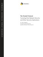
Figure 8 shows the two key infrastructure elements of EDGE (and GPRS) networks. These are the
Serving GPRS Support Node (SGSN) and Gateway GPRS Support Node (GGSN). The SGSN handles the
direct communications with mobile devices, sending and receiving data and keeping track of their
location. The GGSN is the gateway to other networks such as the Internet or even select customer
networks. The GGSN also handles functions such as IP address assignment and user-level authentication.
16
Figure 8: EDGE network and security protocol
EDGE employs a number of different security protocols. The first is authentication of the user device
(phone or modem) by the SGSN. Secondly, communications between the user device and the SGSN is
encrypted using a ciphering protocol developed for GPRS by the ETSI Security Algorithms Group of
Experts (SAGE) protocols.
There is an additional level of authentication that can optionally be invoked. When registering with the
network, the user device can use either the Challenge Authentication Protocol (CHAP) or Password
Authentication Protocol (PAP) to obtain a password from the user. This password is forwarded to the
GPRS Gateway Support Node (GGSN) that can submit the password to an authentication server, such as
a Remote Authentication Dial-In User Service (RADIUS) server, for user-level authentication.
IPSec is likely to be used between the SGSN and GGSN to secure communications. IPSec could optionally be
used to set up secure tunnels between the EDGE network and customer networks.
With respect to migrating applications from CDPD to EDGE, the security features provided by EDGE
will be as good if not better than CDPD. Both CDPD and EDGE provide device authentication and both
encrypt communications over the airlink. EDGE provides a mechanism for user-level authentication that
CDPD does not. If a customer has implemented a VPN solution that spans from the M-ES to F-ES using
CDPD, this same solution should work with EDGE. If a customer has implemented access control lists at
their firewalls to restrict traffic to the M-ES with particular IP addresses, this approach should also work,
though EDGE networks will handle the management of IP addresses differently from CDPD networks.
Base Station
EDGE Network
Internet
IPSec
CHAP/
PAP
SAGE
Optional
IPSec
SGSN
Serving
Node
Note: CHAP/PP used between device and mobile computer, but actual password authenticated by the GGSN
SGSN: Serving GPRS Support Node
GGSN: Gateway GPRS Support Node
GGSN
Gateway
Node
17
Appendix A: Data-Security Technologies and Standards
This section provides a brief overview of some security technologies, protocols and standards in use
today that are relevant to wireless-data networks.
Authentication
A digital signature can be encrypted in a message to provide authentication of the sender’s identity. For
example, Alice, to sign a message, does a computation that involves both her private key and the message
itself. The output of this computation, the digital signature, is attached to the message. To verify the
signature, Bob does another computation that involves the message, the purported signature, and Alice’s
public key. If the results properly hold up in a simple mathematical relationship, the signature is verified
as authentic; otherwise, the signature may be fraudulent or the message may be altered, and they are
discarded. Messages can also be authenticated using a session key that was created from a shared
secret key.
Certificates
Certificates are digital documents that associate an individual or other entity with a public key. This
allows other parties to verify with a high degree of confidence that the individual or entity is who they
claim to be. This can be important when providing access to particular computing resources or information,
or for e-commerce transactions. The most commonly used format for certificates is defined by the
International Telecommunications Union (ITU) X.509 standard. Certificates are validated at the time they
are used by sending messages to trusted certificate authorities. Certificate authorities are either private
or public systems, and must be able to authenticate themselves before their responses can be trusted.
The AT&T Wireless IP network does not use certificates, but since it is an IP network, digital certificates
can be readily employed over the network for purposes of authenticating both mobile users as well as
fixed-end services.
DES and AES
DES is the Data Encryption Standard, an encryption block cipher defined and endorsed by the U.S.
government in 1977 as an official standard. Since then, DES has become the most well known and widely
used encryption system in the world.
DES is a secret-key system; when used for communication, both the sender and receiver must know the
same secret key. This secret-key is used to both encrypt and decrypt the message. DES is designed to be
implemented in system hardware. DES is relatively fast, and works well for bulk encryption of large
amounts of data. DES and Triple-DES are two cryptographic methods available for SSL.
DES uses a 56-bit key. This size key is suitable for much of business communications, but is becoming
vulnerable. Triple-DES is a method that improves the strength of DES. Triple-DES can be implemented in
several different ways, one way is to encrypt the data three times using three different keys. The U.S.
government is now using Triple-DES.
The National Institute of Standards (NIST) is in the process of establishing an encryption standard called
Advanced Encryption Standard (AES) to replace DES. AES will be more secure than DES, and is intended
to be the U.S. encryption standard for the next several decades.
Diffie-Hellman Key Exchange
The Diffie-Hellman key agreement protocol allows two users to exchange a secret key over an insecure
medium without requiring either user to know a prior secret-key. It is different than public-key
cryptography. This method is used within CDPD networks between the M-ES and the MD-IS to create
a session key that is used for encrypting data communications.
The implementation within CDPD is explained in detail in “Appendix B: CDPD System Specification
Security Requirements.”
18
Encryption and Key Management
Encryption is the first step in the process of cryptography and involves transformation of data into a
form that is unreadable by anyone without a secret decryption key. Its purpose is to ensure privacy by
keeping the information hidden from anyone for whom it is not intended, even those who can actually
see or capture the encrypted data.
In a multi-user environment, encryption allows secure communications over an insecure channel. In a
simple example, Alice wishes to send a message for Bob’s eyes only. To keep the message secure, Alice
encrypts the message (called plaintext) with an encryption key, and the encrypted message (called
ciphertext) is sent to Bob. Bob, who knows the secret key, decrypts the ciphertext and reads the
message. An eavesdropper may either try to obtain the secret key or to recover the plaintext without
using the key. Traditional cryptography is based on the sender and receiver of a message knowing and
using the same secret key. The main problem with this method is getting the secret key to both the
sender and receiver without diversion to an intruder.
In 1975, public-key cryptography was invented by Whitfield Diffie and Martin Hellman to solve the key
management problem. This method of encryption uses the concept of a pair of keys, one public and one
private key. The public key is made public by distributing it widely; the private key is never distributed
and is always kept secret. The need for each person to share secret information is eliminated; all
communications involve only public keys, and no private key is ever transmitted or shared. Now, when
Alice wants to send a private message to Bob, she looks up Bob’s public key in a directory, uses it to
encrypt the message, and sends it off. Bob then uses his private key to decrypt the message and read it.
No one can decrypt the message without Bob’s private key, thus eliminating the requirement for complex
key management schemes with private key systems. However, public-key cryptography does require a
public-key infrastructure (PKI) so users can securely and reliably obtain public key information. Such
infrastructure is not yet broadly available.
Firewalls
A firewall is a system or a group of systems that enforces an access control policy between multiple
interconnected networks. A firewall protects the network from unauthorized access while its connected
to other networks. This is especially true for public networks, such as the Internet. All traffic in and out
of the network goes through the firewall. Only the authorized traffic defined by the security policy can
pass. The firewall itself must be highly resistant to penetration.
The importance of a firewall becomes apparent when one considers that the AT&T Wireless IP network
can connect to many other networks, including other wireless IP networks, customer networks, value-added
service networks, online information services, and the Internet. If a data device (for example, an
F-ES) in a corporate network is connected to the AT&T Wireless IP network, all or part of the corporate
network is effectively connected to the AT&T Wireless IP network and, indirectly, to these other networks.
Internal firewalls are one of the built-in protections used by the AT&T Wireless IP network to restrict
customer traffic that is not legitimate. For example, the AT&T Wireless IP network is designed to
prevent traffic that originates on the Internet from reaching the F-ES on the customer’s network. While
these measures do offer some degree of protection, the customer’s firewall design should not rely on
them solely.
19
Firewall Design and Implementation Issues
A firewall represents a trade-off between cost, convenience for network users, and the degree of security
offered. There is no single, standard firewall security solution. Firewall security can be compared with
the physical security provided for buildings and property. Just as there are many types of physical security
systems, including locks, barricades, fences, alarm systems, and security guards, there are many options
when developing network security.
A firewall can be custom-built or purchased off-the-shelf from any number of companies specializing in
this technology. There are two types of firewalls:
• Router-Based Filter: This is the most common type of firewall. It consists of a router that filters
traffic based on an IP address. While effective in many instances, it is difficult for such a router-based
filter to eliminate all unwanted traffic.
• Bastion Host Gateway: This is the most powerful type of firewall. This gateway restricts network
traffic based on application type. This approach allows a company to configure their firewall so that
only specific applications can communicate across the firewall.
One component of firewall design that is gaining in popularity is the use of reverse Domain Name
Service (DNS). In its more standard implementation, DNS is used to translate between convenient
Internet user names (e.g., ) and Internet addresses. Reverse DNS may be
employed as an added security measure to act as a simple form of authentication for addresses that have
passed the firewall filter. If the filtered address does not resolve via reverse DNS to that of the expected
name, the session may be aborted.
Internet Key Exchange (IKE)
IKE was formerly known as Internet Secure Association Key Management Protocol (ISAKMP). IKE is a
key management standard that has been selected for IPSec.
Intrusion Detection Systems
To implement a comprehensive security policy, it is not sufficient to simply secure specific interfaces and
connections. It is also important to monitor network traffic to detect whether there are attempts to
break into the network and whether these are successful. This is the purpose of Intrusion Detection
Systems. These systems compare network traffic against predefined attack patterns, a process analogous
to virus detection systems comparing code against malicious virus code.
Generally, an organization would implement a detection system only after it has addressed audit, policy
and architectural issues. The detection systems then become a powerful complement to the existing
firewall deployment.
Layer 2 Tunneling Protocol (L2TP) and Point-to-Point Tunneling Protocol (PPTP)
L2TP is a standard being developed that allows PPP connections to flow over the Internet rather than over
direct dial-up connections. These connections can carry a variety of networking protocols, including IP,
the Microsoft
®
NetBEUI and the Novell IPX/SPX
™
. L2TP allows a dial-up connection to an Internet Service
Provider, with the remainder of the connection occurring across the Internet. Clients connect to an
L2TP server at a corporate network, which allows the L2TP network server to authenticate the user rather
than the ISP.
L2TP is an effort that combines work done by Microsoft with PPTP and the Cisco Layer 2 Forwarding
(L2F). It should ultimately result in one industry standard. L2TP is currently available in draft form.
Microsoft currently offers PPTP with Windows NT
®
Server version 4.0 and will probably continue making
it available until L2TP becomes firmly established.
L2TP supports uses Challenge Authentication Protocol (CHAP) for authentication, but does not itself
provide encryption. If operated over an IP network, the underlying IP communications can be encrypted
using IPSec.
Encryption and user authentication for PPTP use the Microsoft
®
Point-to-Point Encryption (MPPE) which
uses RSA RC4
®
encryption. Authentication is based on MS-CHAP. Support for PPTP is included in
Windows NT
®
Server version 4.0 and Windows
®
98. Support for L2TP is expected in Windows
®
2000.
20
Public-Key versus Secret-Key Cryptography
Secret-key cryptography uses a single key for encrypting and decrypting communications. The advantages
are that it is simple and computationally efficient. The disadvantage is that it can be difficult to distribute
the keys securely.
By contrast, with public-key cryptography private keys are never transmitted or revealed to anyone
except the user. Another advantage is that public-key cryptography allows irrefutable authentication of
the sender’s identity.
A disadvantage of using public-key cryptography is speed; currently popular secret-key methods are
significantly faster than any public-key method. The best solution is often to combine public-key and
secret-key systems to get both the security advantages of public-key systems and the speed advantages of
secret-key systems.
For example, the public-key system can be used to encrypt a secret key, which is then used to encrypt
the bulk of a file or message to gain the speed advantage. Public-key encryption is not meant to replace
secret-key cryptography, but rather to supplement it, to make it even more secure. The first use of
public-key techniques was for secure key exchange in an otherwise secret-key system, and this is still one
of its primary functions.
RC4
®
RC4
®
is the encryption method used to secure communications over the AT&T Wireless IP airlink. It is a
stream cipher developed by RSA Data Security Inc. The variable key-size cipher can be implemented
efficiently in software. According to RSA, independent analysts who have scrutinized the algorithm
consider it secure. It is also one of the encryption methods available for Secure Sockets Layer (SSL)
protocol, the protocol used to secure communications between Web clients and Web servers.
Secure IP (IPSec)
IPSec is the result of fifteen years of security research, and provides a comprehensive set of standards
and protocols for secure communications, including key management, encryption, authentication, methods
for negotiating authentication and encryption and tunneling. It consists of seventeen Rocs, the most
important of which are RFC 1825 to RFC 1829. IPSec is not yet complete, but is far enough along that
products are becoming available that implement it. IPSec is required for IPv6 implementations. IPsec’s
underlying philosophy is that it is better to secure communications at the network layer than at the
application layer.
Two standards in particular, Authenticating Header (AH) Specification and Encapsulated Security Payload
(ESP) are considered key for future VPN implementations. IPSec can interoperate with L2TP, or it might
eventually replace it.
IPSec does not address access rights, namely the authorized services available to particular users on
particular networks.
Secure Sockets Layer (SSL) and Transport Layer Security (TLS)
SSL, now at version 3.0, is a protocol developed by Netscape Communications and is commonly used to
secure communications between Web clients and Web servers. But SSL can be used with any application.
It resides above the transport layer of communications protocols stacks (e.g. TCP/IP) and below
applications. SSL provides algorithms to authenticate both client and server to each other. The SSL
protocol negotiates the type of encryption to be used, including RC2, RC4
®
, IDEA, DES, and Triple-DES.
These are all symmetric encryption methods. This means both sender and receiver use the same key.
To prevent tampering of messages, the MD-5 Message Digest Algorithm can be used.
The SSL HandShake Protocol is used at the beginning of a session and consists of two phases. In the first
phase, the server authenticates itself to the client using its public key, and a master key is created for
subsequent communications. In the second phase, which is optional, the client authenticates itself with
the server using its public key.
21
The IETF has a working group called Transport Layer Security (TLS) to evolve the standard from a
de facto standard to an Internet rfc standard.
Within the AT&T Wireless IP network, SSL is used to secure communications between the PocketNet
®
gateway and the PocketNet
®
application servers.
Simple Key Management for IP (SKIP)
SKIP is a draft Internet standard. It provides three levels of network security. One is authorization
control, which controls which systems are permitted to communicate with a SKIP host. The second level
is data authentication where SKIP uses the Hashed MD5 authentication algorithm to verify that data sent
by a remote system truly originated from that system and was not altered. The third level is encryption
of the data.
SKIP is an optional key management protocol for IPSec. SKIP uses a hierarchy of constantly changing
keys. SKIP is typically implemented underneath the IP layer. In the Windows
®
environment, it can be
implemented as a Network Device Interface Specification (NDIS) driver.
SOCKS
SOCKS is an Internet security standard. The latest version, SOCKS version 5 specified in RFC 1928, is
a circuit-level (session layer) proxy protocol that provides access control, monitoring, and logging.
Circuit-level proxies establish a proxy connection between an internal user and an external host or
between an external user and an internal host. The proxy uses a virtual circuit between the client and
the host for the duration of a session.
In the case of an external client, all communication is between the external client and a SOCKS server.
The SOCKS server relays packets to the end host, but before doing so performs security functions such
as decrypting packets and determining whether the client is authorized to access the particular service.
SOCKS 5 supports two types of authentication: Username/password (RFC 1929) and GSS-API-based
authentication (RFC 1961). SOCKS also includes support for both private-key and public-key encryption.
Appendix B: CDPD System Specification Security Requirements
Overview
This section is written for a more technical audience than the previous sections. It includes a detailed
description of the technical implementation of CDPD security and assumes a basic understanding of
network security concepts.
Objectives of the CDPD Security System
The security services provided across the airlink interface support the following security functions:
• Data Link Confidentiality. All information contained in the information fields of SN-DATA
Protocol Data Units (PDUs), including the Network Entity Identifiers (NEIs) of the M-ESs, is
transmitted across the airlink in an encrypted form, once secret keys have been determined.
• M-ES Authentication. Each NEI used by the M-ES is authenticated by the CDPD network to
ensure that only the authorized possessor of the NEI is using the NEI.
• Key Management. All secret keys required to operate the encryption algorithms to support the
first two functions are managed by the network.
• “Upgradeability.” The network can support upgrade or replacement of the algorithms used to
support the first three functions.
• Access Control. The network can support restrictions on access by or to different NEIs, such as
restrictions by location, screening lists, and so on. Access control is not specifically an airlink function.
22
The security services across the airlink interface do not support any other security functions, including
the following:
• Bilateral Authentication. The security services do not validate the CDPD network to the M-ES
across the airlink. The security services do not support bilateral authentication of the NEIs of the
source and destination N-Entities.
• End-to-End Data Confidentiality. The security services do not provide end-to-end data
confidentiality. They provide data confidentiality only over the airlink.
• Data Integrity. The security services do not provide protection against modification of encrypted
data transmitted across the airlink.
• Non-repudiation. The security services do not provide protection against repudiation of
commitments entered into by a user of the security services.
• Traffic Flow Confidentiality. The security services do not provide protection against monitoring
of the volume of data exchanged by users of the security services.
Users of the airlink security services who require any of these other security services must provide them
by other means.
Overview of the Security Protocol
Functions Performed
Both the M-ES and the MD-IS perform the following security functions:
• Exchange of secret keys to be used for encryption and decryption of data transmitted across the
airlink.
• Encryption and decryption of data transmitted across the airlink.
• Exchange of authentication data across the airlink.
For a particular M-ES, these functions are performed between the M-ES and its serving MD-IS. The MD-IS
performs the following additional services:
• Exchange of authentication data with the home MD-IS.
• Notification to the M-ES of the results of the authentication procedure of the home MD-IS.
Security Operations
Key Exchange
Key exchange procedures are required for management of the encryption function. These procedures
are modeled as being performed by a Security Management Entity (SME). An SME is resident in each
M-ES and in the MD-IS.
The SME may be thought of as a sub-entity of the management entity responsible for coordinating and
controlling other activities related to airlink operation. The SME is accessed as a Network Entity using
Sub-Network Dependent Convergence Protocol (SNDCP) with a Network Layer Protocol Identifier
(NLPI) value of 1.
Data Encryption and Decryption
Data encryption and decryption are performed within the subnetwork layer of the airlink. These
functions are performed on a sequential stream of SN-DATA PDUs. Data encryption and decryption are
performed transparently to the users of the SNDCP services.
Encryption and decryption are not performed on SN-UNITDATA PDUs.
23
Authentication
Authentication procedures are required for validation of NEI registration. These procedures are
modeled as being performed by a Mobile Network Registration Protocol Management Entity (MME).
An MME is resident in each M-ES and in the MD-IS.
It is required that the authentication functionality in the M-ES be supported in the Subscriber Identity
Module (SIM) in the event that the SIM is implemented as a detachable module. The MME is accessed as
a network entity using Sub-Network Dependent Convergence Protocol (SNDCP) with a Network Layer
Protocol Identifier (NLPI) value of 0.
Services Required
Key Exchange
Communication between the SMEs for purposes of key exchange takes place using the SN-UNITDATA
primitives of the subnetwork layer, with the Acknowledged SN-QUALITY-OF-SERVICE as defined in Part
404 of the CDPD specification.
Encryption and Decryption
Each SME controls the encryption activities of the subnetwork layer through the primitive MSN-
KEYLOAD.request. This primitive supplies a pair of keys to the subnetwork layer. It has the following
mandatory parameters:
ENCRYPTION KEY: the key used to encrypt transmitted data.
DECRYPTION KEY: the key used to decrypt received data.
KEY SEQUENCE NUMBER: the value of the K bit to be used when transmitting data encrypted under
the associated ENCRYPTION KEY.
Authentication
Authentication exchanges take place using the Mobile Network Registration Protocol (MNRP) defined in
Part 507 of the CDPD specification. Authentication data sent by the M-ES to the MD-IS is transferred in
the Authentication parameter option in the END SYSTEM HELLO (ESH) message. Authentication
updates sent by the MD-IS to the M-ES are transferred in the Authentication Update parameter option in
the MD-IS INTERMEDIATE SYSTEM CONFIRM (ISC) message.
“Upgradeability”
Provision is made for support of multiple link encryption algorithms and multiple authentication proce-
dures. This allows support for new procedures to be phased in, for example by replacement of Sub-
scriber Identity Modules (SIMs) or by download of new security code to the M-ES.
Protocol Functions
This section defines the basic algorithms used to provide security across the airlink for each of the
defined objectives.
Key Management
Key management is based on an Electronic Key Exchange (EKE) procedure, which is executed after initial
establishment of the underlying data link connection but before the registration and authentication of any
NEI. The procedure may be re-executed from time to time to change the encryption keys used by the
data link encryption algorithm. The entire procedure must be executed in order to change keys. The
keys must be re-synchronized after every re-establishment of the data link connection.
Key Exchange
In order to execute the algorithm, the M-ES generates a secret random quantity x, and the serving MD-IS
another secret random quantity y. The procedures used to generate these random quantities are
implementation-dependent. The size of the random quantities x and y are implementation-dependent but
cannot exceed 256 bits, nor be fewer than 40 bits. Smaller sizes allow the algorithm to be executed
more rapidly, but correspondingly reduce the security of the procedure.
24
The MD-IS also generates two public quantities, a base a, and a modulus p, which must be a prime
number larger than a. Both a and p are 256 bits long. The MD-IS may optionally use different values of
a and p for different executions of the key exchange algorithm.
The serving MD-IS initiates and controls the execution of the key exchange algorithm. It initiates the
algorithm by transmitting to the M-ES a triplet, consisting of (a, p, a y mod p), in the MD-IS INTERNET
KEY EXCHANGE (IKE) message. The M-ES replies by transmitting the quantity (a x mod p) to the
MD-IS in the M-ES ELECTRONIC KEY EXCHANGE (EKE) message. The M-ES and the MD-IS then both
generate (a xy mod p), which is a shared secret quantity. All of these numbers are 256 bits long.
The M-ES and the serving MD-IS derive a pair of shared secret keys (k 0, k 1) from (a xy mod p) using
procedures specific to the data link encryption algorithm. k 0 is the shared secret key used to encrypt and
decrypt transmissions in the forward direction. k 1 is the shared secret key used to encrypt and decrypt
transmissions in the reverse direction. Thus k 0 is the encryption key for the MD-IS and the decryption
key for the M-ES, while k 1 is the decryption key for the MD-IS and the encryption key for the M-ES.
The IKE message and the EKE message are transmitted using the Acknowledged service class via the
SN-UNITDATA primitive. After each initial establishment of the underlying data link connection, the IKE
message is the first message transmitted by the MD-IS. The M-ES responds with the EKE message before
commencing the registration process defined in Part 507 of the CDPD specification. After each re-
establishment of the data link connection, the EKE message is the first message transmitted by the M-ES.
Secret Key Derivation
The choice of encryption algorithm is determined by the MD-IS, and is specified in the IKE message.
The procedures to derive (k 0 , k 1) from (a xy mod p) for each of the supported algorithms are as
follows:
• RC4
®
: The size of the secret keys is N bits, whose value is set by the MD-IS at key creation time, in
association with the key exchange procedures. N is at least 40 and does not exceed 128. k 0 consists
of the most significant N bits of (a xy mod p). k 1 consists of the least significant N bits of (a xy mod p).
• Test: Test mode is reserved for test and experimental purposes. Key derivation, if any, is defined by
pre-arranged agreement on a pair-wise basis.
Key Changes
Once a key pair (k 0, k 1) has been loaded via the key exchange procedure, the pair remains in use until
either a new key pair is loaded or until the mobile data link is released via the DL-RELEASE.indication
primitive.
Each key pair is associated with a one-bit key sequence number. The value of this sequence number is
incremented after every execution of the key exchange procedure across the airlink, upon receipt of the
MSN-KEYLOAD.request primitive (i.e., the key sequence number alternates between 0 and 1 on each
completed execution of the key exchange procedure). The initial value of this sequence number, after the
first execution of the key exchange procedure, is 0. Between the initial establishment of the data link
connection and the completion of the first key exchange procedure executed thereafter, and between
receipt of a DL-RELEASE.indication primitive and the completion of the first key exchange procedure
executed thereafter, the sequence number is 1. The SN-DATA PDUs transmitted during this period
containing IKE and EKE messages are unencrypted. The initial transition of the sequence number from 1
to 0 marks the commencement of encryption on the mobile data link.
The current value of the key sequence number held by the originator of an SN-DATA PDU is quoted on
all SN-DATA PDUs in the K bit provided within SNDCP, as defined in Part 404 of the CDPD Specification.
The transmitter of an SN-DATA PDU encrypts the SN-DATA PDU using the encryption key associated
with the key sequence number quoted in the transmitted SN-DATA PDU. A new encryption key,
associated with a new key sequence number, is used in place of the encryption key associated with the
old key sequence number as soon as the new key is loaded via the MSN-KEYLOAD.request primitive.
25
The receiver of the SN-DATA PDU decrypts the SN-DATA PDU using the decryption key associated
with the key sequence number quoted in the received SN-DATA PDU. After receipt of a decryption key
associated with a new key sequence number via the MSN-KEYLOAD.request primitive, both decryption
keys are maintained for a period of time. The receiver continues to decrypt received SN-DATA PDUs
using the old decryption key until the received key sequence number changes. At that point, the old
decryption key is no longer used and the receiver begins using the decryption key associated with the
new decryption number.
The execution of the key exchange algorithm at any time after the initial execution of the algorithm is
sufficient to ensure that at least one SN-DATA PDU is transmitted in each direction encrypted under the
key associated with any given key sequence number.
Key Resynchronization
Upon re-establishment of the data link connection, the MD-IS and M-ES execute procedures to
resynchronize encryption keys. The MD-IS reloads the current keys using the MSN-KEYLOAD.request
primitive. SN-DATA PDUs encrypted under keys associated with a different key sequence number and
received before the next execution of the MSN-KEYLOAD.request primitive are discarded. Upon data
link re-establishment, the M-ES performs the following procedure:
• Reload the set of keys in use before the last transmission of the EKE message via the MSN-
KEYLOAD.request primitive, or return to an unencrypted state if at most one key exchange has
taken place.
• Retransmit the last transmitted EKE message.
• Reload the current set of keys (if different) via the MSN-KEYLOAD.request primitive.
SN-DATA PDUs received before the procedure above has been completed are discarded.
Encryption and Decryption
Point-to-point information transfer over the acknowledged data link service is encrypted once the key
exchange procedure has been completed. Information transfer over the unacknowledged data link
service (i.e., broadcast and multicast information transfer) is not encrypted.
A pair of shared secret keys is created by the M-ES and the serving MD-IS using the key exchange
procedure. Once the key exchange procedure has been executed, the DATA SEGMENT fields of all
SN-DATA PDUs transmitted by any entity are encrypted using an encryption algorithm and the shared
secret keys, except possibly in the event of link reestablishment.
The encryption algorithm is an algorithm selected from the following set by the M-ES:
• RC4
®
• Test mode
• Others to be defined
Support for additional algorithms may be provided within the specification from time to time or by the
operators of individual CDPD networks. All networks and all M-ESs must support the RC4
®
algorithm to
ensure interoperability, and to ensure that they do not impact applications or protocol stacks on either
the M-ES or the F-ES.
SN-UNITDATA PDUs are not encrypted using the data link encryption algorithm.