(LUẬN án TIẾN sĩ) nghiên cứu tổng hợp tio2 AC, tio2 GO và đưa lên gốm cordierite làm xúc tác cho quá trình quang phân hủy metyl da cam và phenol
Bạn đang xem bản rút gọn của tài liệu. Xem và tải ngay bản đầy đủ của tài liệu tại đây (2.81 MB, 150 trang )
MINISTRY OF EDUCATION AND TRAINING
HANOI UNIVERSITY OF SCIENCE AND TECHNOLOGY
Nguyen Trung Hieu
RESEARCH INTO TiO2/AC, TiO2/GO SYNTHESIS AND COATING ON
CORDIERITE CERAMIC APPLIED AS CATALYSTS FOR
PHOTODEGRADATION OF METHYL ORANGE AND PHENOL
DOCTORAL DISSERTATION IN CHEMICAL ENGINEERING
Hanoi – 2022
MINISTRY OF EDUCATION AND TRAINING
HANOI UNIVERSITY OF SCIENCE AND TECHNOLOGY
Nguyen Trung Hieu
RESEARCH INTO TiO2/AC, TiO2/GO SYNTHESIS AND COATING ON
CORDIERITE CERAMIC APPLIED AS CATALYSTS FOR
PHOTODEGRADATION OF METHYL ORANGE AND PHENOL
Major
: Chemical Engineering
Code No
: 9520301
DOCTORAL DISSERTATION IN CHEMICAL ENGINEERING
ADVISOR: Prof. Le Minh Thang
Hanoi – 2022
GUARANTEE
The study has been conducted at the School of Chemical Engineering (SCE),
Germany and Vietnam catalyst research center (Gevicat), Hanoi University of Science
and Technology (HUST).
I affirm that this is my own research. The co-authors consented to the use of all the
data and findings presented in the thesis and confirmed their veracity. This study has not
been published by anybody but me.
Hanoi, Octorber 25th 2022
Thesis Advisor
PhD student
Prof. Le Minh Thang
Nguyen Trung Hieu
i
ACKNOWLEDGEMENTS
I would like to express my sincerest and heartfelt gratitude to the following people
and organizations whose valuable contributions and assistances have made my research
possible:
To Hanoi University of Science and Technology, specifically to the School of
Chemical Engineering, Department of Organic and Petrochemical Technology for
providing the laboratory instruments and the equipment for me to accomplish my
research.
To - Catalyst Program, for letting me be an official member of the sponsored
research on modified TiO2 synthesis and methyl orange and phenol photocatalytic
degradation at Hanoi University (HUST) and National Taiwan University (NTU).
To my thesis adviser, Prof. Dr. Le Minh Thang, for giving me guidance and
supervision as well as critiques and comments on my progress reports to bring me
patience, finance, and power to finish this research.
To Prof. Dr. Jeffrey Chi-Sheng Wu, for allowing me to be a part of his research
team under the RoHan Program and for training me in his Lab at NTU.
To my family and friends who always try to encourage and motivate me during
my thesis course, especially since it is the late gift for my father in heaven now.
ii
TABLE OF CONTENTS
GUARANTEE .................................................................................................................i
ACKNOWLEDGEMENTS ......................................................................................... ii
TABLE OF CONTENTS ............................................................................................ iii
LIST OF ABREVIATIONS.........................................................................................vi
LIST OF TABLES ...................................................................................................... vii
LIST OF FIGURES ................................................................................................... viii
INTRODUCTION .........................................................................................................1
1. Necessity of the study ............................................................................................. 1
2. Objectives of the study ...........................................................................................3
3. Content of the thesis ............................................................................................... 4
4. Methodologies of the study ....................................................................................4
5. Scope of the study ...................................................................................................4
6. Scientific and practical meanings .........................................................................5
7. Novelty of the study ................................................................................................ 5
8.Structure of the thesis ............................................................................................. 5
CHAPTER 1. LITERATURE REVIEW ....................................................................6
1.1. Textile industry and Methyl Orange dye ..........................................................6
1.2.
Phenol in industry and its impact to the health ............................................8
1.3. Titanium dioxide, TiO2 .......................................................................................9
1.4.
Principles of Precipitation, sol-gel and hydrothermal synthesis methods 13
1.4.1.
Preparation of photocatalyst using sol-gel method.................................15
1.5. Support and thin films ......................................................................................19
1.5.1 Overview of Cordierite ..................................................................................19
1.5.2 Mesoporous TiO2 and coating techniques ...................................................20
1.5.3
Catalyst Suspension and immobilization.................................................21
1.6
TiO2/AC Materials .........................................................................................22
1.7
Graphene oxide (GO) ....................................................................................26
1.8
TiO2/GO Materials .........................................................................................28
1.9
MO photocatalytic degradation ....................................................................31
1.10 Phenol photocatalysis degradation ............................................................... 36
1.11 Summary .........................................................................................................38
iii
CHAPTER 2 EXPERIMENTS ..................................................................................40
2.1 Materials and instruments ................................................................................40
2.2 Catalyst preparation ………………………………………………………….42
2.2.1 Synthesis of mesoporous TiO2 ......................................................................42
2.2.2. Synthesis of TiO2 and AC/TiO2 by Sol-gel method.....................................45
2.2.3. Synthesis of TiO2 GO by sol-gel method .....................................................46
2.2.4. Synthesis of TiO2 films on cordierite .......................................................... 48
2.3 Characterization of the catalysts ......................................................................54
2.3.1 Morphology on the surface...........................................................................54
2.3.2. Elemental surface composition and traces of impurities .......................... 56
2.3.3
Specific surface area, pore volume, and average pore size ....................56
2.3.4
Crystal structures formed and the crystallite diameter ........................... 57
2.3.5. Absorbance ...................................................................................................58
2.3.6. UV-Vis DSR .................................................................................................60
2.3.7. High-performance liquid chromatography analysis .................................60
2.4 Experimental set up ........................................................................................... 62
2.5. To calculate the efficiency of photocatalytic process .....................................63
2.5.1 Construct calibration curve of methyl orange solution............................... 63
2.5.2 Calculation the concentration via equation.................................................64
CHAPTER 3 RESULTS AND DISSCUSSIONS ......................................................65
3.1. Mesoporous TiO2 synthesized by precipitation and hydrothermal with
CTAB and P123 surfactants ....................................................................................65
3.1.1 Characterization results ................................................................................65
3.1.2. MO photocatalytic degradation of
mesoporous TiO2 photocatalysts
prepared by precipitation and hydrothermal methods with surfactants (CTAB
and P123) ...............................................................................................................69
3.2. TiO2/AC catalyst synthesized using sol-gel method .......................................74
3. 2.1. Characterization Catalyst ...........................................................................74
3.2.2. Photocatalytic activity of the MO in water.................................................77
3.3. GO-TiO2 catalysts by sol-gel method ............................................................. 83
3.3.1. Characterization.......................................................................................... 83
3.3.2 MO photocatalytic degradation by TiO2 – GO .………………………. …….86
iv
3.4. TiO2 films ..........................................................................................................89
3.4.1. TiO2 films on Cordierite ..............................................................................89
3.4.2. TiO2 nanocatalysts thin film by the CVD method on various substrates100
3.5. Phenol photocatalytic degradation ...............................................................107
CHAPTER 4: CONCLUSIONS AND RECOMENDATONS ..............................115
REFERENCES ..........................................................................................................116
v
LIST OF ABREVIATIONS
Symbols
Meaning
UV
Ultraviolet radiation
MO
methyl orange
GO
graphene oxide
FTIR
Fourier transform infrared spectroscopy
SEM
Scanning electron microscopy
FE SEM
Field Emission
EDX
Energy-dispersive X-ray spectroscopy
P123
poly(ethylene glycol)-block-poly(propylene glycol)-block-poly
(ethylene glycol)
CNT
carbon nanotube
LPMOCVD
Low pressure chemical vapor deposition
AC
activated carbon
TTIP
titanium tetraisopropoxide
UV–VIS
Ultraviolet- Visible
HPLC
High-performance liquid chromatography
XRD
X-ray diffraction
BET
Brunauer, Emmett and Teller
SEM
Scanning electron microscopy
CTAB
cetyl trimethyl ammonium bromide
PEG
polyethylene glycol
vi
LIST OF TABLES
Table 1.1. The General Mechanism of the Photocatalytic Reaction Process on TiO2 [49]
.......................................................................................................................................11
Table 1.2. Summary of TiO2 and GO composites used as photocatalyst ......................30
Table 2.1: List of chemicals .......................................................................................... 40
Table 2.2: List of main instruments ...............................................................................41
Table 2.3: Catalyst synthesized by hydrothermal and precipitation methods using
surfactant. ......................................................................................................................44
Table 2.4 : AC to TiO2 Ratio with Corresponding Theoretical % Weight AC in AC/TiO2
catalyst ........................................................................................................................... 45
Table 2.5: Catalysis films and powders synthesized by various methods with the low
concetration of PEG. .....................................................................................................50
Table 2.6: Catalyst films and powders synthesized by various methods with higher
concentration of PEG. ...................................................................................................52
Table 3.1: The surface characteristics of catalysts synthesized by hydrothermal and
precipitation methods ....................................................................................................66
Table 3.2: Crystalline sizes of catalysts ........................................................................68
Table 3.3: Surface area of two samples by sol-gel synthesis . ......................................75
Table 3.4: Crystalline sizes of catalysts ........................................................................77
Table 3.5: Surface area of GO-TiO2 catalysts .............................................................. 85
Table 3.6: Crystalline sizes of catalysts ........................................................................86
Table 3.7: Effect of ratio mol TTIP:H2O to the catalyst mass coated .......................... 89
Table 3.8: Catalysts films coated cordierite .................................................................93
Table 3.9: Apparent first-order rate constant kapp and correlation coefficient R2 for
phenol degradation by catalysts synthesized by various methods ..............................109
Table 3.10: Apparent first-order rate constant kapp and correlation coefficient R2 for
phenol degradation with various initial concentrations by P123-C25-450 catalyst ..110
Table 3.11: Apparent first-order rate constant kapp and correlation coefficient R2 for
phenol degradation by P123-C25-450 catalyst with various concentrations H2O2 ...112
Table 3.12: Apparent first-order rate constant kapp and correlation coefficient R2 for
phenol degradation in visible light condition ..............................................................113
vii
LIST OF FIGURES
Fig. 1.1: Chemical structure of MO molecule [33,34] ...................................................7
Fig. 1.2: TiO2 Crystal Structures[44] ............................................................................9
Fig. 1.3: The mechanism of photocatalytic activity of TiO2 [50] ................................ 11
Fig. 1.4: Nanocrystalline Metal Oxide Preparation using Sol-Gel method .................17
Fig. 1.5: Structures of graphene, C60, CNT and graphite [109] .................................27
Fig. 1.6: Structure of GO [110] ....................................................................................27
Fig. 1.7: Possible mechanism of MO with TiO2 [142] .................................................34
Fig. 1.8: Production Distributions from Phenol Decomposition Reaction [152] ........38
Fig. 2.1. Flowchart of TiO2 synthesis using CTAB. ......................................................42
Fig. 2.2. Flowchart of TiO2 synthesis using P123. .......................................................43
Fig. 2.3: Flowchart of GO synthesis ............................................................................46
Fig. 2.4: Flowchart of GO-TiO2 (GO-ZnO) synthesis .................................................47
Fig. 2.5: Dip-coating TiO2 on the surface of cordierite. ..............................................49
Fig. 2.6: Experimental LPCVD set-up. .........................................................................53
Fig. 2.7: Simplified internal structure of FESEM. ........................................................54
Fig. 2.8: Energy band diagram of a semiconductor (Zeghbroeck, 2007). ...................60
Fig. 2.9: Principle diagram of a HPLC system. ........................................................... 61
Fig. 2.10a: Photocatalytic exerimental setup with UV-C lamp ...................................62
Fig. 2.10 b: Principle diagram of visible photocatalytic exerimental setup................63
Fig. 3.1: Nitrogen isotherm of CTAB-NE and P123 C25-450. ....................................66
Fig. 3.2: Pore size distribution of CTAB-NE and P123 C25-450. ................................ 67
Fig. 3.3: XRD paterns of catalysts synthesized with surfactants CTAB and P123 .......68
Fig. 3.4: FE-SEM images of CTAB-H (a) and P123 C25-450 (b).............................. 69
Fig. 3.5: Evaluation of the catalysts using CTAB by two hydrothermal and precipitation
methods .......................................................................................................................... 70
Fig. 3.6: The influence of citric acid amount to catalyst performance .........................71
Fig. 3.7:The influence of Ethanol elimination method to catalyst performance ..........72
Fig. 3.8: Comparing the best catalyst via hydrothermal and precipitation .................73
Fig. 3.9: Nitrogen isotherm of SG TiO2 and SG AC1200 TiO2 1/18 ............................ 74
Fig. 3.10: Pore size distribution of SG TiO2 and SG AC1200 TiO2 1/18. ....................75
Fig. 3.11: Morphology of SG AC-1200/Ti 1/18 (a) and SG AC-1200/Ti 3/1 (b) ........76
viii
Fig. 3.12: EDX analysis results of samples: SG AC-1200/Ti 1/18 (a); SG AC-1200/Ti
2/1 (b);. .......................................................................................................................... 76
Fig. 3.13: XRD result of AC TiO2 catalysts ..................................................................77
Fig. 3.14: MO dark adsorption of AC. ..........................................................................78
Fig. 3.15: MO photodegration is affected by activated carbon category. ....................79
Fig. 3.16: MO photodegradation via time of catalyst samples at pH=7. ....................80
Fig. 3.17: MO photodegrdation of samples at pH= 4. ...............................................81
Fig. 3.18: MO photodegradation of samples at pH= 10. .............................................82
Fig. 3.19: Comparison the MO photodegradation SG AC1200 Ti/1/18 by pH. ..........83
Fig. 3.20: Nitrogen isotherm of G1/4, G1/18, G1/24....................................................84
Fig. 3.21: Pore distribution of SGGO Ti1/4, SG GO Ti1/18,SG GO Ti1/24 ................84
Fig. 3.22: XRD analysis of GO catalyst. ......................................................................86
Fig. 3.23: The effect of GO content to MO photocatalytic degradation .......................87
Fig. 3.24: Photodegradation of TiO2 GO catalysts with MO concentration 20 ppm in
the full range Xenon lamp ............................................................................................. 88
Fig. 3.25 Photodegradation of SG GO Ti/ 1/18 MO for various concentration ...........88
Fig. 3.26: (a) SEM Cor-gel-200 and (b) SEM Cor-gel-CTAB ......................................89
Fig. 3.27: Investigate the efficiency of catalyst thin films by dip coating with low
concentration of PEG ....................................................................................................90
Fig. 3.28: SEM characterization: (a) Cor-CTAB, (b) Corgel 200 (c) Cor-P123. ........92
Fig. 3.29: SEM characterization of 2 samples Corgel-150AC (a) and Cor-P123 (b)
after the first reaction. ...................................................................................................92
Fig. 3.30: The photocatalytic degradation of four samples Corgel-150, Corgel-150AC,
Corgel-200 and AC-gel powder ....................................................................................94
Fig. 3.31: Surface of Corgel-150 (left) and Corgel-150AC (right) after reaction ......94
Fig.3.32: (a) Surface of Corgel 150AC (left) and Corgel-200 (right);(b)Inside view of
Corgel-150AC (left) và Corgel-200 ( right) ..................................................................95
Fig. 3.33: Photocatalytic performance of-P123 and Cor-P123 samples ....................96
Fig. 3.34: MO Photodegradation by CTAB powder and Cor-CTAB............................ 97
Fig. 3.35: MO Photodegradation with three TiO2 films coated on cordierite ..............98
Fig. 3.36: The TiO2 film performance in the first and second times. ........................... 99
Fig. 3.37: SEM characterization of TiO2 on the surface of (a) glass, (b) aluminium, (c)
cordierite with 25,000 magnification; SEM characterization of TiO2 on the surface of
ix
(d) glass, (e) aluminum and (f) ceramic with 100,000 magnification. EDS
characterization of TiO2 on the surface (g) glass, (h) aluminum and (i) c cordierite.
.....................................................................................................................................101
Fig. 3.38: 10x Microscopy of TiO2 (a) 120oC; (b) 150oC; (c) 200oC; (d) 250oC; (e)
300oC. ..........................................................................................................................102
Fig. 3.39: 10x Microscopy of TiO2 thin film on glass substrate at 580 mm-bar pressure
at position opposite (a) and next (b) nozzle. ...............................................................103
Fig.3.40: 10x Microscopy of TiO2 thin film on glass substrate at 700 mm-bar pressure
at position opposite (a) and next (b) nozzle. ...............................................................103
Fig. 3.41: 10x Microscopy of TiO2 thin film on glass substrate with carrying gas N2 300
ml/min. .........................................................................................................................104
Fig. 3.42: Visual image of TiO2 thin film on various substrates.................................104
Fig. 3.43: 10x Microscopy of TiO2 thin film on various substrates ............................104
Fig. 3.44: TiO2 thin film performance for MO photodegradation with UV-C...........105
Fig. 3.45: TiO2 thin film performance for MO photodegradation with full range lamp
.....................................................................................................................................106
Fig. 3.46: Phenol degradation evaluation and kinetics study in UV light.................108
Fig. 3.47: Effect of the initial concentration to the phenol degradation in UV condition
and kinetics study by P123-C25-450 ...........................................................................109
Fig. 3.48: Effect of H2O2 loading and kinetics study in phenol degradation process.
.....................................................................................................................................111
Fig. 3.49: Phenol degradation process and kinetics study in visible light ..................113
x
INTRODUCTION
1. Necessity of the study
Soil and groundwater resource pollution are serious concerns in our nation. One of
the unavoidable effects of uncoordinated economic zone growth is the contamination of
water sources with heavy metals and harmful, persistent organic compounds such as
phenol and its derivatives. The primary sources of phenol and phenol polluting
compounds are the manufacture of synthetic plastics, insecticides, paints, and petroleum
[1]. Additionally, the textile sector emits a significant number of harmful chemical
compounds into the atmosphere, including azo-based dyes, one of which is methyl
orange. As a result, the remediation of contaminated environments with two chemical
compounds as phenol and methyl orange, is a hot topic not only in the nation, but also
globally.
Historically, remediation of polluted water has been mostly dependent on
physicochemical and biological treatment approaches. Among these, adsorption is one
of the most frequently used strategies for treating chemical contaminants in water due
to its ease of use and the broad application of a variety of adsorbents. Another workable
solution is biological treatment, which may eliminate around 90% of organic debris
entirely. However, this procedure is less efficient for compounds that are difficult to
decompose, such as phenol and methyl orange. Numerous extensive research studies
have been undertaken to process the aforementioned chemicals, which include
electrochemical methods, ion exchange, ozone, and adsorption on activated carbon [2,
3]. In the other hand, these approaches are rarely used in reality due to their inherent
constraints, which include heavy equipment systems, complex operation techniques,
high initial and ongoing expenditures, and birth abnormalities. It must include a sludge
post-treatment step, otherwise the efficiency will remain poor results.
Using photocatalysts to treat polluted water is one of the most environmentally
friendly green treatment methods available, since it employs natural solar energy and is
capable of degrading organic contaminants that are difficult to decompose. Without the
addition of extra chemicals or sludge buildup in the treatment system [4]. TiO2, ZnO,
and Fe2O3 are among the semiconductor materials that researchers are interested in as
potential photocatalysts. Due of titanium dioxide's (TiO2) outstanding characteristics, it
is the most investigated material. It is ecologically safe, chemically and physiologically
1
inert, self-cleaning, and produces minimal byproducts during production [5].
TiO2 nanoparticles have played a key role in the photodegradation of organic
pollutants; it seems to be the most investigated photocatalyst due to its cheap cost,
photostability, abundance, and high oxidizing power against a wide range of organic
pollutants [6,7]. Despite these positive qualities, its use is limited due to its large band
gap (3.2 eV), the difficulty in separating the catalyst TiO2 from the solution, and the
recombination of the photogenerated electron-hole pairs, which results in low
photocatalytic reaction efficiency [8]. TiO2 is effective in decomposing a vast array of
organic, inorganic, and toxic compounds in liquid and gas phase environments.
However, the 3,2 eV energy band gap of pure TiO2 limits its use to UV light (387 nm,
or about 4% of solar radiation). Numerous approaches have been used to improve the
photocatalytic activity of TiO2, including two major classes of chemical treatments,
including doping with non-metals, transition metals, dye sensitization, spatial
structuring, and doping with rare earth metals [9]. Alternative methods include infusing
microwave or ultrasonic radiation into TiO2 photoreaction systems [10]. Activated
carbon may be an ideal substrate for evaluating the drawbacks of TiO2 when supported
by activated carbon.
. This new discovery has a great deal of potential as a result of the synergy between
the photocatalytic activity of the catalyst and the adsorptivity of the activated carbon.
The use of commercial activated carbon as an effective adsorbent for the removal of
organic pollutants from liquid phase [11] is well established. However, due to the
prohibitive cost involved, its use is severely limited. Activated carbon may also be
produced from waste products derived from agricultural by-products [12] and the wood
industry, as well as non-conventional waste items from municipal and industrial
operations. The use of waste materials in the manufacturing of activated carbon may be
of significant benefit in minimizing waste disposal in the environment, which may have
further impacts. Activated carbon may be produced by using waste materials. When
using TiO2, one of the most important obstacles that must be overcome is separating the
powder catalyst from the effluent at high concentrations, which might result in the
coagulation of the catalyst as well as the creation of aggregates [13].
Activated carbon's high porosity, high surface area, high photostability, and
appropriateness for use at room temperature are some of the benefits that accrue from
2
using TiO2 in conjunction with activated carbon. Other advantages include the ease with
which the catalyst can be extracted from the bulk solution. Other materials than activated
carbon, such as clays [14], zeolite [15], silica [18], alumina [16], and glass, were used
in an attempt to boost the photocatalytic efficacy of the catalyst; however, these other
materials did not make a significant contribution. It's possible that the synergistic effect
of activated carbon and TiO2 is what's responsible for the promising nature of the combo.
Sometimes the reaction between TiO2 and a specific pollutant can result in coagulation,
which will prevent a significant amount of UV or solar radiation from reaching the
catalyst's active core. This can happen in a number of different ways. This resulted in
the reduction in the surface area of the catalyst, which in turn led in a decrease in its
photocatalytic activity [17]. Because the activated carbon at the surface of the TiO2
functions as an efficient adsorption trap for the organic pollutant, this results in the mass
transfer of the pollutant to the surface of the catalyst, which is where the photoreaction
takes place. It has been shown that the higher adsorption of the substrate onto the surface
of the carbon in activated carbon contributes to the enhanced photocatalytic elimination
of pollutants [19,20]. This effect is attributed to activated carbon.
In order to broaden the absorption spectrum of the TiO2 catalyst to include the
visible light area, which accounts for about 45 percent of solar energy, it is necessary to
incorporate metal or nonmetallic alteration methods into the structure of the TiO2
material. Since solar energy is a renewable and endless source of energy, this step is
necessary because it is required to broaden the absorption spectrum of the TiO2 catalyst.
Recently, a number of researchers have begun using graphene oxide in an effort to
enhance the performance of TiO2 photocatalysts. This is owing to the multiple
advantages that graphene oxide offers in terms of enhancing catalytic performance under
circumstances of visible light. [21-25]
2. Objectives of the study
The general objective of this study is to produce catalysts TiO2 modified with
activated carbon and graphene oxide, coated on various materials to degrade organic
pollutants in wastewater, which is represented by methyl orange and phenol as two
harmful substances popular in many textile and other industrial factories, at Vietnam
and in the world.
3
The other aims are to investigate the process parameter in catalyst synthesis, to
find out the optimum catalysts of each synthesis methods, to make the thin films of
catalyst on various substrates to degrade methyl orange, to modify catalyst to have
positive results in full range light condition.
3. Content of the thesis
Firstly, literature review on previous studies will be investigated to select the
preparation methods of the catalysts, materials to modify catalyst, coating techniques
and model pollutants to conduct research
The photocatalyst TiO2 was synthesized by sol-gel, co-precipitation and
hydrothermal methods. After that, catalysts were modified with activated carbon and
graphene oxide, silica gel then the catalysts were characterized by physical adsorption,
SEM, XRD, UV-Vis.
The catalytic activities of these catalysts were conducted for methyl orange and
phenol, one stable organic compound, in UV-C and full range light condition.
The main process parameters in phenol photodegradation of the optimum catalysts
were evaluated and do kinetics study this process.
4. Methodologies of the study
Literature review: it is a general section to collect related data from previous
researches such as the catalyst composites with activated carbon and graphene oxide,
the preparation methods, coating methods, methyl orange and phenol photodegradation.
Experiments: the catalysts were prepared by sol-gel, co-precipitation, and
hydrothermal methods, then characterized by various techniques such as BET physical
adsorption, SEM, XRD. Finally, the photodegradation performances of these catalysts
were evaluated using specific reactor systems combined with UV-Vis and HPLC
methods.
Data analysis and processing: the method is used to gather and determine the
concentration of methyl orange and phenol based on the calibration curve of these
substances.
5. Scope of the study
Organic pollutants: Methyl orange and phenol were chosen to evaluate the catalyst
performance since they are popular pollutants in wastewater.
4
Catalyst thin films: Catalyst thin films made by dip coating and CVD methods on
various substrates as cordierite, glass and aluminum are studied.
6. Scientific and practical meanings
The thesis can provide a scientific background to synthesize the photocatalyst TiO2
in methyl orange and phenol in laboratory condition. Since methyl orange and phenol
are popular and difficult compounds to be degraded with aromatic compound, a catalyst
with positive efficiency to degrade them will be certainly possible to photodegrade other
pollutants.
The catalysts were synthesized in thin films by dip coating and CVD methods. The
parameters and method in making thin films were investigated which can further apply
to treat industrial wastewater.
7. Novelty of the study
The main innovations of this research include:
1. Process parameter optimization for catalysts synthesized via co-precipitation,
hydrothermal, and sol-gel methods.
2. Catalytic film formation optimization on various substrates using CVD
(chemical vapor deposition) and dip coating.
3. Research on the modification of catalysts synthesized by sol-gel and
hydrothermal methods on activated carbon and graphene oxide carriers appliedd in the
treatment of methyl orange and phenol.
8.Structure of the thesis
The thesis consists of four main chapters. The first chapter summarizes the
literature on methyl orange (MO) and phenol contamination, and the methods for
preparing titanium dioxide (TiO2) to improve its performance in the photocatalytic
degradation of MO and phenol. The second chapter describes the synthesis method to
prepare the various catalysts, introduce basic principles of the physico-chemical
methods used as well as the experimental set-up utilized in the thesis. The third chapter
focuses on evaluating the properties of the prepared catalysts, and the influence of
different synthesis methods on the catalytic performance of the catalysts in the
photodegradation of methyl orange and methyl orange phenol.
Finally, the fourth chapter summarizes the main points of the thesis and gives some
recommendations for future works.
5
CHAPTER 1. LITERATURE REVIEW
This chapter presents the previous research that are related to this study as TiO2
catalyst, preparation method of photocatalyst, photodegradation for MO and phenol,
TiO2/AC and TiO2/GO materials, coating techniques ... et al.
1.1. Textile industry and Methyl Orange dye
The textiles and garment industry of Vietnam has been a critical area for the
Vietnamese economy for a long time. The industry employs over 3 million employees
and has over 7,000 factories throughout the country. As a sector relies heavily on water
supply for its development and produces wastewater as a result, it is crucial for
stakeholders in the sector to better understand the water threats they pose, their impacts
and the possible approaches they provide to these challenges [26].
In the textile and dye business, wastewater is produced throughout the steps of
sizing, cooking, bleaching, dying, and finishing. These processes may be broken down
into their individual stages here. The quantity of wastewater produced is mostly
attributable to the washing procedure that occurs after each cycle. The amount of water
that is required in a textile industry is quite high, although the amount varies greatly
from item to item. The examination of specialists indicates that the quantity of water
used in the manufacturing stages amounts for 72.3% of the total, with the majority of
this water coming from the dyeing and finishing stages of the goods. One may do a
rough calculation that places the water need for one meter of fabric anywhere in the
range of 12–65 liters and the amount of water discharged somewhere between 10–40
liters. Water contamination is the most significant environmental issue that the textile
sector faces. The textile dyeing business is regarded to be the most polluting of all
industries when two parameters, namely the volume of wastewater and the types of
pollutants that are included within the wastewater, are taken into consideration.[27,28].
The primary contaminants in textile dyeing wastewater include persistent organic
chemicals, dyes, surfactants, organic halogen compounds, neutral salts that enhance the
total solids content, and temperature. Due to the high alkalinity, the effluent pH is also
high. Among these, dyes are the most complex to process, particularly azo dyes, which
account for 60-70 percent of the dye industry [29-32]. During the dyeing process, the
pigments in the dyes do not normally attach themselves to the fibers of the cloth;
nonetheless, a certain quantity of the pigments still stays in the wastewater. There may
6
be as much as fifty percent of the original quantity of color left in the material after it
has been dyed [29-30]. Because of this, the wastewater that is produced from the textile
dyeing process has a strong color and a significant concentration of contaminants.
Methyl orange, often known as MO, is an anionic azo dye that has found
widespread use in a variety of different sectors, including those dealing with textiles,
printing, paper, pharmaceuticals, food, photography, and leather. Methyl orange and the
various compounds that come from it are responsible for significant amounts of
pollution that are released into the environment. It has been shown that this coloring
agent may cause cancer as well as genetic mutations [33]. In addition to being a dye that
is soluble in water, methyl orange is characterized by a high degree of stability as well
as unique color qualities. This compound has an orange appearance when it is in a basic
medium, but it has a red appearance when it is in an acidic media. It was discovered that
the reductive breakage of the azo bond (–N=N–) by the azo reductase enzyme that is
present in liver creates aromatic amines, and that these aromatic amines may potentially
contribute to intestinal cancer if they are taken by human humans [34].
Fig. 1.1: Chemical structure of MO molecule [33,34]
Methyl orange, also known as (C14H14N3SO3Na), served as the model pollutant for
the purpose of this investigation. Methyl Orange is a typical kind of azo-dye that is used
in the industrial sector. It is prized for the stability that it has. Up to 70% of today's dyes
are made up of azo-compounds, which are synthetic inorganic chemical chemicals.
These compounds are used to make colors. It is believed that somewhere between 10
and 15 percent of the dye that is used in the production of textiles is wasted and emitted
as effluent. The discharge of this effluent is referred to as "non-aesthetic pollution" since
the concentrations that are visible in water sources are lower than 1 parts per million.
Although this is the major reason for degrading methyl orange, the dye waste water may
also create harmful byproducts through other chemical processes such as oxidation and
hydrolysis [35-37]. Although this is the primary motive for degrading methyl orange, it
is not the only motivation. These azo-compounds are quite stable, as was previously
7
said, and this is because the dye contains a significant amount of aromatics. Biological
treatments may not be able to degrade the dye effluents; instead, they could only change
the color of the effluents.
1.2. Phenol in industry and its impact to the health
The chemical compound known as phenol (C6H6OH) was found for the first time
in 1834 during the distillation of coal. It was first referred to as a carbolic acid since coal
distillation was the primary source of phenol synthesis up to the advent of the
petrochemical industry. At the moment, quite a few different chemical processes have
been discovered that may be used to generate phenol. In particular, a large number of
steel plants discharge wastewater that contains phenol chemicals. Pure phenol is either
colorless or white in appearance. In this state, phenols are solid crystals that may persist
in air for an extended period of time. Partial oxidation of phenol causes the material to
take on a pink hue and causes it to break down when it comes into contact with water
vapor. The concentration of phenol at which an odor can be detected begins at 0.04 ppm;
at this level, the phenol has an odor that may be described as mildly pungent and
pungent. Phenol plays a very important part in industry; it is the raw material that many
factories use to produce plastics, chemical silk, agricultural pharmaceuticals, antiseptics,
fungicides, pharmaceuticals, dyes, and explosives [38,39]. In addition, phenol is the
source material for many other industries that produce plastics.
Phenol may enter the human body by inhalation as well as through contact with
the skin, eyes, and mucous membranes. When ingested, substances with a high phenol
content will lead to a fatal phenomenon with symptoms such as convulsions, inability
to control, coma leads to respiratory disorders, blood changes in the body leading to a
drop in blood pressure. Phenol is considered to be extremely toxic to humans when it
enters the body of a human through the mouth. When a person is poisoned by phenol, it
first affects their liver, and then it goes on to attack their heart. When individuals were
subjected to phenol for extended periods of time in a number of different trials, it was
found that they experienced pain in their muscles and an enlargement of their livers.
Burns to the skin and irregular heartbeats are also side effects of phenol's contact with
the skin. The amount of phenol that may legally be present in a human body is capped
at 0.6 milligrams per kilogram of total body weight. There are no studies on the effect
of phenol at low concentrations on the development of the body at this time; however,
many scientists believe that chronic exposure to phenol can lead to growth retardation,
cause abnormal changes in the next generation, and increase the rate of premature birth
8
in a pregnant woman [40-42].
In a nutshell, phenolic compounds are one of the most commonly used chemical
compounds in the manufacturing industry. On the other hand, they are also toxic
compounds that can be extremely hazardous to both organisms and humans if they are
not treated properly before being released into the environment. Because the wastewater
from the Formosa - Ha Tinh factory in Vietnam, which has been discharged into the
marine environment, contains high levels of phenol, which has caused the death of a
large number of fish in the coastal provinces in the central part of our country, it is
necessary to take measures to thoroughly treat this phenomenon. The level of chemical
contaminants in waste water is rather high, particularly those that are long-lasting
organic chemicals like phenol and its derivatives. Because of this, phenol degradation is
considered to be of critical significance not just in Vietnam but also across the whole
globe [43].
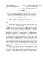
1.3. Titanium dioxide, TiO2
Rutile
Anatase
Brookite
Fig. 1.2: TiO2 Crystal Structures[44]
Titanium Dioxide, often known as TiO2 or titania, is a substance that has received
a significant amount of attention and study owing to the stability of its chemical
structure, biocompatibility, as well as its physical, optical, and electrical characteristics.
TiO2 is a multipurpose substance that may be used in a wide variety of goods, including
pigments for paint, sunscreen lotions, electrochemical electrodes, capacitors, solar cells,
and even as a food coloring additive in toothpaste [45]. TiO2 was created and put to use
in the previous two decades with the primary goal of ridding the environment of harmful
chemical compounds, particularly those found in air and water. TiO2 may be used to
9
lessen the amount of pollutant substances in the air, such as volatile organic compounds,
or perhaps get rid of them entirely. In the presence of sunshine, the photocatalysis of
titanium dioxide (TiO2) has the potential to break down and eliminate hazardous
chemical molecules [46].
Figure 1.2 illustrates the arrangement of the various crystal structures of titanium
dioxide. There is one stable phase of TiO2 known as Rutile (tetragonal), as well as two
meta-stable phases known as Anatase (tetragonal) and Brookite (orthorhombic), both of
which have the potential to transform into Rutile when exposed to temperatures outside
of their normal range. When compared to the Anatase form, the recombination rate of
the surplus charged carriers in the Rutile structure is often seen to be greater. In addition
to this, it is known to occupy the charged transfer that occurs between the catalyst and
the potential reactants. This provides a fundamental explanation for why rutile form of
titanium dioxide (TiO2) is used in paint formulation rather than the anatase form, which
has a much slower recombining rate but is far more efficient in charged transfer. TiO2's
anatase phase, which has a band gap of 3.2eV, has been shown to be TiO2's most active
crystal structure. This is largely due to the fact that it has favorable energy band positions
and a high surface area [47, 48]. Rutile, which has a band gap of 3.0, is used in a wide
variety of applications, the majority of which are in the pigment industry. Anatase has a
band gap of 3.2eV and another thing to take into account is the wavelengths that
correspond to the anatase and rutile phases of titanium dioxide, which are 388 for
anatase and 410 for rutile, respectively.
As a semiconductor, TiO2 may be photo-activated to create a redox environment
that can destroy organic and inorganic contaminants. In Table 1.1, we can see the
overarching steps that occur throughout the photocatalytic reaction process on irradiated
TiO2.
Photodegradation of pollutants by TiO2 begins with UV radiation absorbed by the
TiO2 particles, with a band gap value of 3.2eV for Anatase and 3.0eV for Rutile. By
doing so, holes and electron pairs are generated in the valence band (hole) and
conduction band (electrons) of the semiconductor, respectively (Eq. 1, Table 1.2).
(electron). To clarify, although both Anatase and Rutile type TiO2 absorb UV radiation,
Rutile type TiO2 may also absorb radiation that is closer to visible light. In contrast to
Rutile-type TiO2, Anatase-type TiO2 has more photocatalytic activity because of its
conduction band location, which reveals better reducing power. Both the absorbed
energy and the kinetic energy of the recombining holes and electrons may be used in the
10
redox processes (Eq. 5, Table 1.2). Electron donors and acceptors adsorbed on the
semiconductor surface or even just close the double layer encircling the particle will
participate in the redox reactions, which occur when an electron or hole with sufficient
energy crosses the double layer.
Table 1.1. The General Mechanism of the Photocatalytic Reaction Process on TiO2 [49]
No. Process
1 Electron-hole pair
Reaction Steps
TiO2 + hv → TiO2-+ OH - (or TiO2+)
Formation
2 (semiconductor valence band
TiO2- + O2 + H+→ TiO2 + HO2
3 hole and conduction band
4 electron) Electron removal from
TiO2- + H2O2 + H+ → TiO2 + H2O+ OHTiO2-+ 2H+ → TiO2- + H2
the conduction band
5 Hole trapping
H+ + H2O → OH- + H+
6
H+ + HO- → OH•
7 Oxidation of organic pollutant
OH- + O2 + CxOyH(2x-2y+2) → xCO2 + (x
Molecules
8 Nonproductive radical reactions
– y +1)H2O
TiO2- + OH- + H+ → TiO2 + H2O
(recombination)
9
2OH-→ H2O2
10
2HO2- → H2O2 + O2
11
2OH• + H2O2 → H2O + O2
12
2OH• + HCO3- → CO3• + H2O
Fig. 1.3: The mechanism of photocatalytic activity of TiO2 [50]
11
The solid side of the junction between the semiconductor and the liquid creates an
electrical field that separates the energized hole and electron pairs that are unable to
recombine. This allows the holes to migrate to the illuminated part of the TiO2 and the
electrons to migrate to the unlit part of the TiO2 particle surface. The failure of the pairs
to recombine results in the separation of the pairs. The creation of a very reactive but
short-lived hydroxyl radical (OH-) via hole-trapping is generally considered to be the
first step in the process of photocatalytic degradation. This theory is generally accepted.
Either the highly hydroxylated surface of the semiconductor or the direct oxidation of
the pollutant molecules under the influence of UV radiation might result in the formation
of OH. It is also possible that both of these ways of producing OH- occur concurrently
in certain situations. This is another option. This action takes place immediately after
the reduction of adsorbed oxygen species, which may be generated either from dissolved
oxygen molecules (in the aqueous system) or from other electron acceptors that are
accessible in the aqueous system [50].
In the course of this research, the free radicals that are generated as a result of the
photocatalytic activity will assault the organic component that is present in the polluted
water. MO and phenol will be used in the evaluation of the ability of TiO2 to be
manufactured by sol-gel and other ways to play the role of a model chemical found in
waste water. TiO2 may be used in photocatalytic processes in one of two different ways:
either it can be suspended in aqueous fluids or it can be immobilized on support
materials. Quartz sand, glass, activated carbon, zeolites, and noble metals are the
materials that are used for the supports. The fluidized bed reactor [40] and the fixed bed
reactor [40,43] are two examples of various reactor designs that are possible. Matthews
and McEvoy discovered in 1992 that photocatalytic reactors using immobilized
photocatalysts had a reduced efficiency compared to those that used dispersed titania
particles [48].
It has been proposed that the lower efficiencies that can be achieved with
immobilized photocatalyst can be attributed to the following: first, the decreased number
of activated sites in a given photoactivated volume that are available when the catalyst
is immobilized as compared to the same weight of catalyst that is freely suspended; and
second, the mass transfer limitation that may become rate controlling at low flow rates.
This latter issue is especially problematic in the presence of intense illuminations
because it is possible that the mass transport will be unable to keep up with the reaction
occurring at the photoactivated surface, leading to the possibility that the reaction will
become entirely mass-transfer limited. When this occurs, the growing photon intensity
12
will not create a discernible change in the pace at which the reaction occurs.
Akpan and Hameed conducted research on the influence of operational settings on
the photocatalytic degradation of textile colors using TiO2-based photocatalysts[50]. In
addition to this, it has been shown that there are a variety of processes involved in the
manufacturing of photocatalysts based on TiO2. The Sol–Gel process is quite popular
because it makes it possible to produce nanometer-sized crystalline TiO2-based catalysts
powder with a high degree of purity at a temperature that is very low.
1.4. Principles of Precipitation, sol-gel and hydrothermal synthesis methods
❖ Precipitation
After thoroughly dissolving the precursors in water to make the homogeneous
solution, the precipitant is added to the solution to precipitate the solid. This completes
the process of making the homogenous solution. After that, the solids are extracted from
the solution, washed to remove any contaminants, dried in an oven, and calcined at a
high temperature to produce the materials. This approach makes it possible to diffuse
the reactant on an atomic size, which ultimately leads to an increase in the reactants'
capacity to make contact with one another. The fact that the desired ratio of elements in
the product cannot be guaranteed to be achieved using this method is, however, one of
the method's major drawbacks [51].
❖ Sol-gel
The sol-gel method has seen a lot of action in recent years when it comes to the
production of catalytic supports. In preparations that begin with a metal alkoxide, the
alkoxide is first hydrolyzed by the addition of water to an organic medium. This is
followed by polymerization of the hydrolyzed alkoxides by condensation of hydroxyl
and/or alkoxy groups in the alkoxides. The whole solution will become hard and a solid
gel will be created when the level of polymerization and cross-linking of polymeric
molecules becomes considerable. The porosity of this gel, as well as the surface area,
pore volume, pore size distribution, and thermal stability of the final oxide following
calcinations, are all strongly impacted by the size and degree of branching of the
inorganic polymer, as well as the level of cross-linking. If the gel comprises polymeric
chains that have a high amount of branching and cross-linking, the gel will, in general,
have extensive void areas, will be structurally extremely stiff, and the oxide that will
arise from calcinations will mostly have macropores and mesopores. If the gel comprises
polymeric chains that do not branch out much or have many cross-links, then the gel
will have fewer void regions, will be structurally weak, and will thus easily collapse
when calcinations are performed. The oxide that is produced as a consequence consists
13