SIEMENS - simatic STEP 7 from S5 to S7 pptx
Bạn đang xem bản rút gọn của tài liệu. Xem và tải ngay bản đầy đủ của tài liệu tại đây (638.89 KB, 152 trang )
Preface, Contents
Part 1: Planning Your
Conversion
Introduction
1
Hardware
2
Software
3
Part 2: Converting Programs
Procedure
4
Preparing for Conversion
5
Conversion
6
Editing the Converted Program
7
Compiling
8
Application Example
9
Appendix
Address and Instruction Lists
A
Literature List
B
Glossary, Index
Edition 01/2004
A5E00261402-01
STEP 7
From S5 to S7
Converter Manual
SIMATIC
This manual is part of the documentation
package with the order number:
6ES7810-4CA07-8BW0
ii
From S5 to S7, Converter Manual
A5E00261402 01
This manual contains notices which you should observe to ensure your own personal safety, as well as to
protect the product and connected equipment. These notices are highlighted in the manual by a warning
triangle and are marked as follows according to the level of danger:
!
Danger
indicates that death, severe personal injury or substantial property damage will result if proper precautions
are not taken.
!
Warning
indicates that death, severe personal injury or substantial property damage can result if proper precautions
are not taken.
!
Caution
indicates that minor personal injury or property damage can result if proper precautions are not taken.
Note
draws your attention to particularly important information on the product, handling the product, or to a
particular part of the documentation.
The device/system may only be set up and operated in conjunction with this manual.
Only qualified personnel should be allowed to install and work on this equipment. Qualified persons are
defined as persons who are authorized to commission, to ground, and to tag circuits, equipment, and
systems in accordance with established safety practices and standards.
Note the following:
!
Warning
This device and its components may only be used for the applications described in the catalog or the technical
description, and only in connection with devices or components from other manufacturers which have been
approved or recommended by Siemens.
This product can only function correctly and safely if it is transported, stored, set up, and installed correctly,
and operated and maintained as recommended.
SIMATICR, SIMATIC NETR, and SIMATIC HMIR are registered trademarks of SIEMENS AG.
Third parties using for their own purposes any other names in this document which refer to trademarks might
infringe upon the rights of the trademark owners.
We have checked the contents of this manual for agreement with
the hardware and software described. Since deviations cannot be
precluded entirely, we cannot guarantee full agreement. However,
the data in this manual are reviewed regularly and any necessary
corrections included in subsequent editions. Suggestions for
improvement are welcomed.
Siemens AG 2004
Subject to change without prior notice.
Disclaimer of LiabilityCopyright Siemens AG 2004 All rights reserved
The reproduction, transmission or use of this document or its
contents is not permitted without express written authority.
Offenders will be liable for damages. All rights, including rights
created by patent grant or registration of a utility model or design,
are reserved.
Siemens AG
Bereich Automation and Drives
Geschaeftsgebiet Industrial Automation Systems
Postfach 4848, D-90327 Nuernberg
Siemens Aktiengesellschaft
A5E00261402-01
Safety Guidelines
Qualified Personnel
Correct Usage
Trademarks
iii
From S5 to S7, Converter Manual
A5E00261402-01
Preface
This manual supports you when converting S5 programs into S7. With the
information in this manual you can do the following:
• Convert existing S5 programs into S7 programs and subsequently edit them
manually if necessary.
• Incorporate pre-converted S7 functions (previous S5 standard function
blocks) into your S7 programs.
This manual is intended for programmers who wish to use existing S5
programs in S7.
This manual is valid for release 4.0 of the STEP 7 programming software.
Purpose of the
Manual
Audience
Where is this
Manual Valid?
iv
From S5 to S7, Converter Manual
A5E00261402-01
There is a wide range of user documentation available to support you in
configuring and programming an S7 programmable controller which is
intended to be used selectively. The following explanations should make it
easier for you to use the user documentation.
LAD FBD SCL
CFC for
S7
Reference
Manual
Progr.
Manual
User
Manual
GRAPH
for S7
HiGraph
/234/
/231/
/233/ /236/ /250/
/254/
/251/
/252/
/xxx/: Number in the list of references
/235/
System Software for S7-300/S7-400
Program Design
Standard Software for S7 and
M7
STEP 7
Prime
r
/30/
S7-300 Programmable Controller
Quick Start
System Software for
S7-300/400
System and Standard
Functions
Converter
Manual
/230/
Standard Software for
S7-300/S7-400
From S5 to S7
Language Packages
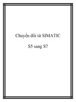
This symbol indicates the order in which you should read the
manuals, particularly if you are a first-time user of S7.
This documentation introduces the methodology.
This is a reference manual on a specific topic.
The documentation is supported by online help.
Symbol
Meaning
Manual
STL
/232/
Manuals on
S7-300/S7-400
Hardware
Figure 1-1 S7 Information Landscape
Where Does this
Manual Fit in with
the Rest of the S7
Documentation?
Preface
v
From S5 to S7, Converter Manual
A5E00261402-01
Table 1-1 S7 Documentation Content
Title
Subject
S7-300 Programmable
Controller
Quick Start,
Primer
The Primer offers a basic introduction to the methodology of the structure and
programming of an S7-300/S7-400. It is especially suited to first-time users of an S7
programmable control system.
S7-300 and S7-400
Program Design
Programming Manual
The S7-300/S7-400 Program Design Programming Manual provides basic
information on the structure of the operating system and of a user program of an S7
CPU. The first-time user of an S7-300 or S7-400 should use this manual to acquire an
overview of the programming methodology and to use it to base their user program
design on.
S7-300 and S7-400
System and Standard
Functions
Reference Manual
The S7 CPUs have integrated system functions and organization blocks included with
their operating system, which you can use when programming. The manual provides
you with an overview of the system functions, organization blocks, and loadable
standard functions available in S7, and – in the form of reference information –
detailed interface descriptions for their use in your user program.
STEP 7
User Manual
The STEP 7 User Manual explains the main usage and the functions of the STEP 7
automation software. As a first-time user of STEP 7 and as an experienced user of
STEP 5, this manual will provide you with an overview of the procedures used to
configure, program, and start up an S7-300/S7-400.
While you are working with the software you can access a range of online help topics
which offer detailed support on using the software.
Converter Manual
From S5 to S7
You will need the From S5 to S7 Converter Manual if you want to convert existing S5
programs to run them on S7 CPUs. The manual provides an overview of the
procedures and usage of the Converter; you can find a detailed description of the
converter functions in the online help. You will also find the interface descriptions for
the converted S7 functions available in the online help. Practical information is also
provided on SIMATIC S7 hardware and software.
Statement List, Ladder
Logic, Function Block
Diagram, SCL
1
Manuals
The manuals for the programming language packages Statement List, Ladder Logic,
Function Block Diagram, and SCL (Sequential Control Language) contain both the
user’s guide and the reference description of the programming language or
representation type. You only require one language type for programming an
S7-300/S7-400, but you can mix the languages within a project, if required. If you are
using a language for the first time, it is recommended that you use the manual to learn
about the methodology of creating a program in the chosen language first.
While you are working with the software you can access a range of online help topics
which offer detailed support on using the respective editors/compilers.
GRAPH
1
, HiGraph
1
,
CFC
1
Manuals
The languages GRAPH, HiGraph, and CFC (Continuous Function Chart) offer
additional methods of programming blocks in the form of sequential controls, state
graphs, or charts. The manuals contain both the user’s guide and the reference
description of the programming language. If you are using a language for the first
time, it is recommended that you use the manual to learn about the methodology of
creating a program in the chosen language first.
While you are working with the software you can access a range of online help topics
which offer detailed support on using the respective editors/compilers (with the
exception of HiGraph).
1
Optional package for system software for S7-300/S7-400
Preface
vi
From S5 to S7, Converter Manual
A5E00261402-01
This manual assumes you have knowledge of S7 programs which you can read
about in the Programming Manual /234/. You should also be familiar with
using the Standard software, as described in the User Manual /231/.
The manual is divided according to the following topic areas:
• Part 1 (Chapters 1 to 3) explains how to plan your conversion from S5 to
S7.
• Part 2 (Chapters 4 to 9) explains how to convert programs with the
converter.
• Chapter 9 contains application examples.
• The Appendix is a reference section on all STL instructions (international
and German mnemonics) provided for reference purposes.
• The Glossary explains important terms.
• The Index will help you to locate text passages on important subjects
quickly and easily.
References to other manuals are shown using the part number of the literature
between slashes / /. Using these numbers you can find out the exact title of
the manual from the literature list at the end of this manual.
If you have any questions regarding the software described in this manual and
cannot find an answer here or in the online help, please contact the Siemens
representative in your area. You will find a list of addresses in the Appendix of
/70/ or /100/, or in catalogs, and in Compuserve (go autforum). You can
also speak to our Hotline under the following phone or fax number:
Tel. (+49) (911) 895 7000 (Fax 7001)
If you have any questions or comments on this manual, please fill out the
remarks form at the end of the manual and return it to the address shown on the
form. We would be grateful if you could also take the time to answer the five
questions giving your personal opinion of the manual.
Siemens also offers a number of training courses to introduce you to the
SIMATIC S7 automation system. Please contact your regional training center
or the central training center in Nuremberg, Germany for details:
D-90327 Nuremberg, Tel. (+49) (911) 895-3154.
This manual replaces the older “Converting S5 Programs” User Manual. In
other manuals, this manual may still be referred to under its old name or
simply as the Converter Manual.
Structure of the
Manual
Conventions
Additional
Assistance
Notes
Preface
vii
From S5 to S7, Converter Manual
A5E00261402-01
Contents
1 Introduction 1-1. . . . . . . . . . . . . . . . . . . . . . . . . . . . . . . . . . . . . . . . . . . . . . . . . . . . . . . . . . . . .
2 Hardware 2-1. . . . . . . . . . . . . . . . . . . . . . . . . . . . . . . . . . . . . . . . . . . . . . . . . . . . . . . . . . . . . . .
2.1 Programmable Logic Controllers 2-2. . . . . . . . . . . . . . . . . . . . . . . . . . . . . . . . . . .
2.2 S7 Modules 2-4. . . . . . . . . . . . . . . . . . . . . . . . . . . . . . . . . . . . . . . . . . . . . . . . . . . . .
2.2.1 Central Processing Units (CPU) 2-6. . . . . . . . . . . . . . . . . . . . . . . . . . . . . . . . . . . .
2.2.2 Power Supply Modules (PS) 2-8. . . . . . . . . . . . . . . . . . . . . . . . . . . . . . . . . . . . . . .
2.2.3 Interface Modules (IM) 2-9. . . . . . . . . . . . . . . . . . . . . . . . . . . . . . . . . . . . . . . . . . . .
2.2.4 Communications Processors (CP) 2-10. . . . . . . . . . . . . . . . . . . . . . . . . . . . . . . . . .
2.2.5 Function Modules (FM) 2-13. . . . . . . . . . . . . . . . . . . . . . . . . . . . . . . . . . . . . . . . . . .
2.2.6 Signal Modules (SM) 2-15. . . . . . . . . . . . . . . . . . . . . . . . . . . . . . . . . . . . . . . . . . . . .
2.2.7 Simulation Modules (S7-300) 2-16. . . . . . . . . . . . . . . . . . . . . . . . . . . . . . . . . . . . . .
2.3 Distributed I/O Devices 2-17. . . . . . . . . . . . . . . . . . . . . . . . . . . . . . . . . . . . . . . . . . .
2.4 Communication 2-18. . . . . . . . . . . . . . . . . . . . . . . . . . . . . . . . . . . . . . . . . . . . . . . . . .
2.4.1 Interface to User Programs 2-20. . . . . . . . . . . . . . . . . . . . . . . . . . . . . . . . . . . . . . . .
2.5 Operator Interface 2-21. . . . . . . . . . . . . . . . . . . . . . . . . . . . . . . . . . . . . . . . . . . . . . . .
3 Software 3-1. . . . . . . . . . . . . . . . . . . . . . . . . . . . . . . . . . . . . . . . . . . . . . . . . . . . . . . . . . . . . . . .
3.1 General Operating Principles 3-1. . . . . . . . . . . . . . . . . . . . . . . . . . . . . . . . . . . . . .
3.1.1 Installation Requirements 3-1. . . . . . . . . . . . . . . . . . . . . . . . . . . . . . . . . . . . . . . . .
3.1.2 Installing STEP 7 Software 3-2. . . . . . . . . . . . . . . . . . . . . . . . . . . . . . . . . . . . . . . .
3.1.3 Starting STEP 7 Software 3-3. . . . . . . . . . . . . . . . . . . . . . . . . . . . . . . . . . . . . . . . .
3.2 Structure of an S7 Project 3-4. . . . . . . . . . . . . . . . . . . . . . . . . . . . . . . . . . . . . . . . .
3.3 Editing Projects with the SIMATIC Manager 3-7. . . . . . . . . . . . . . . . . . . . . . . . .
3.3.1 Creating Projects 3-7. . . . . . . . . . . . . . . . . . . . . . . . . . . . . . . . . . . . . . . . . . . . . . . .
3.3.2 Storing Projects 3-8. . . . . . . . . . . . . . . . . . . . . . . . . . . . . . . . . . . . . . . . . . . . . . . . . .
3.4 Configuring Hardware with STEP 7 3-9. . . . . . . . . . . . . . . . . . . . . . . . . . . . . . . . .
3.5 Configuring Connections in the Connection Table 3-11. . . . . . . . . . . . . . . . . . . .
3.6 Inserting and Editing a Program 3-13. . . . . . . . . . . . . . . . . . . . . . . . . . . . . . . . . . . .
3.6.1 Basic Procedure for Creating Software 3-13. . . . . . . . . . . . . . . . . . . . . . . . . . . . . .
3.6.2 Inserting Components for Creating Software in S7 and M7 Programs 3-15. . .
3.7 Blocks 3-17. . . . . . . . . . . . . . . . . . . . . . . . . . . . . . . . . . . . . . . . . . . . . . . . . . . . . . . . . .
3.7.1 Comparison 3-17. . . . . . . . . . . . . . . . . . . . . . . . . . . . . . . . . . . . . . . . . . . . . . . . . . . . .
3.7.2 Functions and Function Blocks 3-18. . . . . . . . . . . . . . . . . . . . . . . . . . . . . . . . . . . . .
3.7.3 Data Blocks 3-18. . . . . . . . . . . . . . . . . . . . . . . . . . . . . . . . . . . . . . . . . . . . . . . . . . . . .
3.7.4 System Blocks 3-19. . . . . . . . . . . . . . . . . . . . . . . . . . . . . . . . . . . . . . . . . . . . . . . . . . .
3.7.5 Organization Blocks 3-20. . . . . . . . . . . . . . . . . . . . . . . . . . . . . . . . . . . . . . . . . . . . . .
3.7.6 Block Representation during Conversion 3-24. . . . . . . . . . . . . . . . . . . . . . . . . . . .
viii
From S5 to S7, Converter Manual
A5E00261402-01
3.8 System Settings 3-26. . . . . . . . . . . . . . . . . . . . . . . . . . . . . . . . . . . . . . . . . . . . . . . . .
3.9 Standard Functions 3-28. . . . . . . . . . . . . . . . . . . . . . . . . . . . . . . . . . . . . . . . . . . . . .
3.9.1 Floating-Point Math 3-28. . . . . . . . . . . . . . . . . . . . . . . . . . . . . . . . . . . . . . . . . . . . . .
3.9.2 Signal Functions 3-28. . . . . . . . . . . . . . . . . . . . . . . . . . . . . . . . . . . . . . . . . . . . . . . . .
3.9.3 Integrated Functions 3-28. . . . . . . . . . . . . . . . . . . . . . . . . . . . . . . . . . . . . . . . . . . . . .
3.9.4 Basic Functions 3-29. . . . . . . . . . . . . . . . . . . . . . . . . . . . . . . . . . . . . . . . . . . . . . . . . .
3.9.5 Analog Functions 3-29. . . . . . . . . . . . . . . . . . . . . . . . . . . . . . . . . . . . . . . . . . . . . . . .
3.9.6 Math Functions 3-29. . . . . . . . . . . . . . . . . . . . . . . . . . . . . . . . . . . . . . . . . . . . . . . . . .
3.10 Data Types 3-30. . . . . . . . . . . . . . . . . . . . . . . . . . . . . . . . . . . . . . . . . . . . . . . . . . . . . .
3.11 Address Areas 3-32. . . . . . . . . . . . . . . . . . . . . . . . . . . . . . . . . . . . . . . . . . . . . . . . . . .
3.11.1 Overview 3-32. . . . . . . . . . . . . . . . . . . . . . . . . . . . . . . . . . . . . . . . . . . . . . . . . . . . . . .
3.11.2 New Addresses in S7: Local Data 3-33. . . . . . . . . . . . . . . . . . . . . . . . . . . . . . . . . .
3.12 Instructions 3-35. . . . . . . . . . . . . . . . . . . . . . . . . . . . . . . . . . . . . . . . . . . . . . . . . . . . . .
3.13 Addressing 3-39. . . . . . . . . . . . . . . . . . . . . . . . . . . . . . . . . . . . . . . . . . . . . . . . . . . . . .
3.13.1 Absolute Addressing 3-39. . . . . . . . . . . . . . . . . . . . . . . . . . . . . . . . . . . . . . . . . . . . .
3.13.2 Symbolic Addressing 3-39. . . . . . . . . . . . . . . . . . . . . . . . . . . . . . . . . . . . . . . . . . . . .
3.13.3 New Feature: Complete Addressing of Data Addresses 3-41. . . . . . . . . . . . . . .
3.13.4 Indirect Addressing 3-43. . . . . . . . . . . . . . . . . . . . . . . . . . . . . . . . . . . . . . . . . . . . . . .
4 Procedure 4-1. . . . . . . . . . . . . . . . . . . . . . . . . . . . . . . . . . . . . . . . . . . . . . . . . . . . . . . . . . . . . .
4.1 Analyzing the S5 System 4-2. . . . . . . . . . . . . . . . . . . . . . . . . . . . . . . . . . . . . . . . . .
4.2 Creating an S7 Project 4-4. . . . . . . . . . . . . . . . . . . . . . . . . . . . . . . . . . . . . . . . . . . .
4.3 Configuring Hardware 4-4. . . . . . . . . . . . . . . . . . . . . . . . . . . . . . . . . . . . . . . . . . . .
5 Preparing for Conversion 5-1. . . . . . . . . . . . . . . . . . . . . . . . . . . . . . . . . . . . . . . . . . . . . . . .
5.1 Providing the Required Files 5-2. . . . . . . . . . . . . . . . . . . . . . . . . . . . . . . . . . . . . . .
5.2 Checking Addresses 5-3. . . . . . . . . . . . . . . . . . . . . . . . . . . . . . . . . . . . . . . . . . . . .
5.3 Preparing the S5 Program 5-4. . . . . . . . . . . . . . . . . . . . . . . . . . . . . . . . . . . . . . . . .
5.4 Creating Macros 5-5. . . . . . . . . . . . . . . . . . . . . . . . . . . . . . . . . . . . . . . . . . . . . . . . .
5.4.1 Instruction Macros 5-6. . . . . . . . . . . . . . . . . . . . . . . . . . . . . . . . . . . . . . . . . . . . . . .
5.4.2 OB Macros 5-7. . . . . . . . . . . . . . . . . . . . . . . . . . . . . . . . . . . . . . . . . . . . . . . . . . . . . .
5.4.3 Editing Macros 5-8. . . . . . . . . . . . . . . . . . . . . . . . . . . . . . . . . . . . . . . . . . . . . . . . . . .
6 Conversion 6-1. . . . . . . . . . . . . . . . . . . . . . . . . . . . . . . . . . . . . . . . . . . . . . . . . . . . . . . . . . . . .
6.1 Starting the Conversion 6-1. . . . . . . . . . . . . . . . . . . . . . . . . . . . . . . . . . . . . . . . . . .
6.2 Generated Files 6-5. . . . . . . . . . . . . . . . . . . . . . . . . . . . . . . . . . . . . . . . . . . . . . . . . .
6.3 Interpreting Messages 6-8. . . . . . . . . . . . . . . . . . . . . . . . . . . . . . . . . . . . . . . . . . . .
7 Editing the Converted Program 7-1. . . . . . . . . . . . . . . . . . . . . . . . . . . . . . . . . . . . . . . . . . .
7.1 Address Changes 7-2. . . . . . . . . . . . . . . . . . . . . . . . . . . . . . . . . . . . . . . . . . . . . . . .
7.1.1 Options for Changing Addressing 7-2. . . . . . . . . . . . . . . . . . . . . . . . . . . . . . . . . .
7.2 Non-Convertible Functions 7-3. . . . . . . . . . . . . . . . . . . . . . . . . . . . . . . . . . . . . . . .
7.3 Indirect Addressing – Conversion 7-4. . . . . . . . . . . . . . . . . . . . . . . . . . . . . . . . . .
7.4 Working with Direct Memory Accesses 7-5. . . . . . . . . . . . . . . . . . . . . . . . . . . . . .
Contents
ix
From S5 to S7, Converter Manual
A5E00261402-01
7.5 Assigning Parameters 7-5. . . . . . . . . . . . . . . . . . . . . . . . . . . . . . . . . . . . . . . . . . . .
7.6 Standard Functions 7-6. . . . . . . . . . . . . . . . . . . . . . . . . . . . . . . . . . . . . . . . . . . . . .
8 Compiling the Program 8-1. . . . . . . . . . . . . . . . . . . . . . . . . . . . . . . . . . . . . . . . . . . . . . . . . .
9 Application Example 9-1. . . . . . . . . . . . . . . . . . . . . . . . . . . . . . . . . . . . . . . . . . . . . . . . . . . . .
9.1 Analog Value Processing 9-2. . . . . . . . . . . . . . . . . . . . . . . . . . . . . . . . . . . . . . . . . .
9.2 Temporary Local Data 9-5. . . . . . . . . . . . . . . . . . . . . . . . . . . . . . . . . . . . . . . . . . . .
9.3 Evaluating the Start Information from the Diagnostic Interrupt OB (OB82) 9-8
9.4 Block Transfer 9-11. . . . . . . . . . . . . . . . . . . . . . . . . . . . . . . . . . . . . . . . . . . . . . . . . . .
9.5 Calling the Examples 9-14. . . . . . . . . . . . . . . . . . . . . . . . . . . . . . . . . . . . . . . . . . . . .
A Address and Instruction Lists A-1. . . . . . . . . . . . . . . . . . . . . . . . . . . . . . . . . . . . . . . . . . . .
A.1 Addresses A-1. . . . . . . . . . . . . . . . . . . . . . . . . . . . . . . . . . . . . . . . . . . . . . . . . . . . . .
A.2 Instructions A-3. . . . . . . . . . . . . . . . . . . . . . . . . . . . . . . . . . . . . . . . . . . . . . . . . . . . . .
B Literature List B-1. . . . . . . . . . . . . . . . . . . . . . . . . . . . . . . . . . . . . . . . . . . . . . . . . . . . . . . . . . .
Glossary Glossary-1. . . . . . . . . . . . . . . . . . . . . . . . . . . . . . . . . . . . . . . . . . . . . . . . . . . . . . . . . .
Index Index-1. . . . . . . . . . . . . . . . . . . . . . . . . . . . . . . . . . . . . . . . . . . . . . . . . . . . . . . . . .
Contents
x
From S5 to S7, Converter Manual
A5E00261402-01
Contents
Introduction
1
Hardware
2
Software
3
Part 1: Planning Your
Conversion
-2
From S5 to S7, Converter Manual
A5E00261402-01
1-1
From S5 to S7, Converter Manual
A5E00261402-01
Introduction
Until now you were familiar with the name SIMATIC as the synonym for
SIEMENS programmable controllers of the S5 family. Now the name
SIMATIC stands for fully integrated automation.
The concept fully integrated automation describes a revolutionary new way
of combining the worlds of manufacturing and process engineering. All
hardware and software components are integrated into one single system:
SIMATIC.
This complete integration is made possible by the universal compatibility
offered by the S7 system in the following three areas:
• Database
Data are only entered once and are then available to a whole factory.
Transfer errors and inconsistencies are therefore a thing of the past.
• Configuring and programming
All the components and systems belonging to a task are planned,
configured, programmed, commissioned, debugged, and monitored with
one single fully integrated software package with a modular design - under
one user interface and with the most suitable utility.
• Communication
“Who communicates with whom” is determined simply in a connection
table and can be changed at any time. The various network types can be
configured easily and uniformly.
To be able to meet the wide range of possibilities of SIMATIC as a fully
integrated system, brand new concepts have been shaped in SIMATIC S7.
Some functions are therefore achieved in other ways to those you are familiar
with in S5.
The STEP 7 programming software is based on new technology and concepts.
For example, the user interface is designed to meet modern ergonomic
requirements and runs under Windows 95/NT. In our programming languages,
we have endeavored to adhere to the IEC 1131 standard as closely as possible
without becoming incompatible with STEP 5.
1
1-2
From S5 to S7, Converter Manual
A5E00261402-01
We are convinced that our new STEP 7 system meets the following demands:
• A software basis for fully integrated automation
• Programming which conforms to IEC 1131
• Compatibility with STEP 5
We are also aware that converting from an existing system to a new system
gives rise to a number of questions and we recognize that it will be necessary
to make certain adaptations, particularly with regard to the software.
This manual is intended to provide answers to these questions and, at the same
time, show you simple ways in which you can continue to use your existing
STEP 5 programs in SIMATIC S7.
2-1
From S5 to S7, Converter Manual
A5E00261402-01
Hardware
This chapter describes the hardware that can be used for S7 and makes
comparisons, when necessary, with the hardware used for S5, in order to
facilitate the transition from S5 to S7.
The Siemens CD-ROM “Components for Automation” / catalog CA01 (from
4/97) contains an application designed to aid you in choosing hardware when
converting from S5 to S7. To access the catalog of products, select the menu
command Auswahlhilfen > Simatic. Here you can enter any S5 system
desired; the application uses this system data to create a rack configuration and
a signal list. You can then convert this S5 configuration to an S7 configuration.
Converting
Hardware from S5
to S7 using the
Siemens Catalog
on CD-ROM
2
2-2
From S5 to S7, Converter Manual
A5E00261402-01
2.1 Programmable Logic Controllers
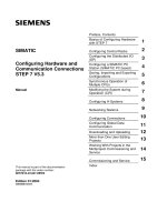
SIMATIC S7 consists of the following three types of programmable logic
controllers classified according to their performance range:
SIMATIC S7-200 is a compact micro programmable logic controller (PLC)
designed for applications having the lowest performance range. S7-200 is
controlled by its own system-specific software package which is not included
in the following comparison of S5 and S7.
SIMATIC S7-300 is a modular mini controller designed for applications
having a low performance range.
SIMATIC S7-400 is designed for applications providing an intermediate to
high performance range.
For easy reference, S7-300 module names always start with a “3” and S7-400
module names with a “4”.
Intermediate
performance range
Lower
performance range
SIMATIC
S7-200
modular
compact
SIMATIC
S7-300
SIMATIC
S7-400
modular
CPU 944/945
CPU
941-943
High
performance range
Figure 2-1 SIMATIC Programmable Controllers
SIMATIC S7-200
SIMATIC S7-300
SIMATIC S7-400
Hardware
2-3
From S5 to S7, Converter Manual
A5E00261402-01
Programming device interface MPI (Multipoint Interface) for
programming devices and operator panels
The programming device interface AS511 used in SIMATIC S5 has been
replaced by the multipoint interface, MPI (for S7-300 and S7-400). This
multipoint interface provides a direct electrical connection for HMI devices
(HMI: Human Machine Interface, previously known as COROS) and for
programming devices to the programming device interface used by SIMATIC
S7. The interfaces are completely integrated.
The following table provides a direct comparison of these two interface
specifications:
AS511
MPI
25-pin TTY interface (20 mA) 9-pin sub-D interface with RS485
technology
Transmission rate: 9.6 Kbps Transmission rate: 187.5 Kbps
Protocol: 3964R Protocol: S7 functions
Max. length of network: 50 m
(with bus amplifiers or special
cables: up to 1000 m)
All programmable modules within a
configuration can be addressed via
the multipoint interface
One device can be connected Up to 31 devices can be connected
Bus interface for Operator Panels (OP)
Programmable logic controllers in the SIMATIC S5 and SIMATIC S7
automation families can be connected using the PROFIBUS (previously
known as SINEC L2) bus system. As before, these connections are
bus-specific.
Connecting
Programming
Devices and OPs
to SIMATIC S7
Hardware
2-4
From S5 to S7, Converter Manual
A5E00261402-01
2.2 S7 Modules
The range of modules used in S7 corresponds to and expands on the known
and proven module concept used in SIMATIC S5.
S7 contains the following types of modules:
• Central processing units (CPU)
• Power supply modules (PS)
• Interface modules (IM)
• Communications processors (CP); (such as for connecting to PROFIBUS)
• Function modules (FM); (such as for counting, positioning, closed-loop
control)
• Digital and analog modules are now called “signal modules” (SM)
This chapter describes the similarities and differences in the range of modules
used in SIMATIC S5 and SIMATIC S7.
S7 modules can be distinguished by the following features:
• The new modules are not equipped with jumpers or switches.
• The new modules do not require cooling fans. As in S5, they have the IP 20
protection class.
• The new modules can be assigned parameters and have diagnostic
capability.
• The S7 slot assignment is more flexible than for S5.
• Expansion devices and ET 200 distributed I/O devices can trigger
interrupts.
No Fundamental
Differences from
S5
New Performance
Characteristics
Hardware
2-5
From S5 to S7, Converter Manual
A5E00261402-01
The following table compares the module parameter assignment in SIMATIC
S5 and SIMATIC S7:
SIMATIC S5
SIMATIC S7
Modules are arranged (hardware
configuration) using the STEP 7
application for configuring hardware
Addresses are set with DIL switches Addresses are set with the STEP 7
application for configuring hardware
or are slot-oriented
System behavior is set with DIL
switches
Module parameters are assigned
with the STEP 7 application for
configuring hardware
CPU parameters for operational
behavior are assigned via system
data areas or DB1 / DX0
CPU parameters are assigned with
the STEP 7 application for
configuring hardware
Compiled configuration data are
downloaded to the CPU;
Module parameters are transferred
automatically on startup
Comparison of
Module Parameter
Assignment in S5
and S7
Hardware
2-6
From S5 to S7, Converter Manual
A5E00261402-01
2.2.1 Central Processing Units (CPU)
Table 2-1 lists the most important performance specifications for S7-300
CPUs. If you want to replace an S5 CPU, you can use the following table to
compare performance in order to select the most suitable CPU:
Table 2-1 Performance Features of the S7-300 CPUs
Feature
CPU 312 IFM CPU 313 CPU 314 CPU 314 IFM CPU 315 CPU
315-2 DP
Work memory
(integrated)
6 Kbytes 12 Kbytes 24 Kbytes 24 Kbytes 48 Kbytes
Load memory
• integrated
20 Kbytes RAM;
20 Kbytes
EEPROM
20 Kbytes
RAM
40 Kbytes
RAM
40 Kbytes RAM;
40 Kbytes
EEPROM
80 Kbytes RAM
• expandable with
memory card
– up to 512
Kbytes
up to 512
Kbytes
– up to 512 Kbytes
(in CPU programmable
up to 256 Kbytes)
Process image size,
inputs and outputs
32 bytes
+ 4 on-board
128 bytes 128 bytes 124 bytes
+ 4 on-board
128 bytes
I/O address area
• digital
inputs/outputs
Inputs: 128
+ 10 on-board
Outputs: 128
+ 6 on-board
128 512 Inputs: 496
+ 20 on-board
Outputs: 496
+ 16 on-board
1024
• analog
inputs/outputs
32 64 Inputs: 64
+ 4 on-board
Outputs: 64
+ 1 on-board
128
Bit memory 1024 2048
Counters 32 64
Timers 64 128
Max. sum of
all retentive data
72 bytes 4736 bytes 144 bytes 4736 bytes
Local data 512 bytes in
total;
256 bytes per
priority class
1536 bytes in total;
256 bytes per priority class
Blocks:
OBs
FBs
FCs
DBs
SFCs
SFBs
3
32
32
63
25
2
13
128
128
127
44
7
13
128
128
127
48
7
13
128
128
127
48
14
13
128
128
127
48
7
14
128
128
127
53
7
S7-300 CPUs
Hardware
2-7
From S5 to S7, Converter Manual
A5E00261402-01
The CPUs for the S7-400 have different performance features. Table 2-2 shows
a comparison of the performance features of these CPUs.
Table 2-2 Performance Features of the S7-400 CPUs
Feature
CPU
412-1
CPU
413-1
CPU
413-2 DP
CPU
414-1
CPU
414-2 DP
CPU
416-1
CPU
416-2 DP
Work memory
(integrated)
48 Kbytes 72 Kbytes
128
Kbytes
128/384
Kbytes
512
Kbytes
0.8/1.6
Mbytes
Load memory
• integrated
8 Kbytes 8 Kbytes 16 Kbytes
• expandable with
memory card
up to 15 Mbytes up to 15 Mbytes up to 15 Mbytes
Process image size,
inputs and outputs
128 bytes each 256 bytes each 512 bytes each
I/O address area
• digital inputs/outputs
max.
• analog inputs/outputs
max.
2 Kbytes
16384
1024
8 Kbytes
65536
4096
16 Kbytes
131072
8192
Bit memory 4096
M 0.0 to M 511.7
8192
M 0.0 to M 1023.7
16384
M 0.0 to M 2047.7
Counters 256
C 0 to C 255
256
C 0 to C 255
512
C 0 to C 511
Timers 256
T 0 to T 255
256
T 0 to T 255
512
T 0 to T 511
Local data 4 Kbytes in total 8 Kbytes in total 16 Kbytes in total
Blocks:
OBs
FBs
FCs
DBs
SFBs
23
256
256
511
24
31
512
1024
1023
24
44
2048
2048
4095
24
SDBs 512 512 512
SFCs 55 55 58 55 58 55 58
The CPUs for SIMATIC S7-400 require a backup battery to buffer timers,
counters, and bit memory.
The CPUs for S7-300 do not require a battery to buffer timers, counters, or bit
memory. Similarly, the contents of data blocks can also be retained in the event
of a power failure. The CPUs for SIMATIC S7-300 have a maintenance-free
backup that saves those addresses and data which have parameters specifying
that they be retained in event of a power failure.
The size and quantity of the available retentive areas depend on the respective
CPU.
The size of the data retention areas is set in parameter assignment dialog boxes
during hardware configuration with STEP 7.
S7-400 CPUs
Retentive Features
of S7-400
Retentive Features
of S7-300 without
Backup Battery
Parameter
Assignment for the
Retentive Feature
Hardware
2-8
From S5 to S7, Converter Manual
A5E00261402-01
2.2.2 Power Supply Modules (PS)
A selection of power supply modules is available for each programmable logic
controller (PLC).
Any 24-volt power source (industrial) can be used to supply to the CPU in
S7-300.
The range of modules in S7 contains the following power supplies specifically
designed for S7-300:
Module Name
Output
Current
Output
Voltage
Input
Voltage
PS 307 2 A 24 VDC 120 / 230 VAC
PS 307 5 A 24 VDC 120 / 230 VAC
PS 307 10 A 24 VDC 120 / 230 VAC
Module Name Output
Current
Output
Voltage
Input
Voltage
PS 407 4A 4 A
0.5 A
5 VDC
24 VDC
120 / 230 VAC
PS 407 10A 10 A
1 A
5 VDC
24 VDC
120 / 230 VAC
PS 407 20A 20 A
1 A
5 VDC
24 VDC
120 / 230 VAC
PS 405 4A 4 A
0.5 A
5 VDC
24 VDC
24 VDC
PS 405 10A 10 A
1 A
5 VDC
24 VDC
24 VDC
PS 405 20A 20 A
1 A
5 VDC
24 VDC
24 VDC
For further information, see the Reference Manuals /71/ and /101/.
Power Supply
Modules for S7-300
Power Supply
Modules for S7-400
Hardware
2-9
From S5 to S7, Converter Manual
A5E00261402-01
2.2.3 Interface Modules (IM)
Some interface modules in S5 have been replaced in S7. This change primarily
affects local area connections. In S7, it is recommended that PROFIBUS be
used to transmit signals for remote area connections.
S5 Module S7-300 Module S7-400 Module Description
IM 305
IM 306
IM 300 / IM 312
IM 365
IM 360 / IM 361
IM 460-0 / IM 461-0
IM 460-1 / IM 461-1
Central configuration
– – IM 460-3 / IM 461-3 Remote area (up to
100 m)
IM 301 / IM 310 Connection via
PROFIBUS
Connection via
PROFIBUS
Connection of I/O
modules and signal
preprocessing modules
(up to 200 m)
IM 304 / IM 314 Connection via
PROFIBUS
Connection via
PROFIBUS
Use of distributed I/O in
remote areas (up to
600 m)
IM 463-2 Distributed connection
of S5 expansion devices
in remote areas (up to
600 m)
IM 307 / IM 317 Connection via
PROFIBUS
Connection via
PROFIBUS
Connection via
fiber-optic cable (up to
1500 m)
IM 308 / IM 318 Connection via
PROFIBUS
Connection via
PROFIBUS
Distances up to 3000 m
In S7, the interface module IM 467 can be used in place of IM 308C.
You can use the interface module IM 463-2 to connect S5 digital and analog
modules to the S7 mounting rack with IM 314 via an S5 expansion rack.
The following S5 expansion racks can be connected:
• EG 183 expansion unit
• EG 185 expansion unit
• ER 701-2
• ER 701-3
Comparison of IM
Modules
Connectable S5
Expansion Racks
Hardware
2-10
From S5 to S7, Converter Manual
A5E00261402-01
2.2.4 Communications Processors (CP)
The following section lists the S5 and S7 communications processors that can
be used in various subnets. In addition, the services supported by these
processors are also indicated.
In order to meet the varying requirements of different automation levels (such
as on the processing, cell, field, and actuator-sensor levels), SIMATIC provides
the following subnets:
• AS Interface
The actuator-sensor interface (AS-i) is a connection system for the lowest
processing level in automation systems. It is primarily used for networking
binary sensors and actuators. Its data quantity is limited to a maximum of
4 bits per slave.
• MPI
The multipoint interface (MPI) subnet is intended for short-range field and
cell levels. The MPI is a multipoint interface used in SIMATIC S7/M7 and
C7. It is designed as a programming device interface and is intended for
networking a small number of CPUs and for exchanging small quantities
(up to 70 bytes) of data.
• PROFIBUS
PROFIBUS is the network used for the cell and field areas in open,
manufacturer-independent, SIMATIC communication systems. PROFIBUS
is suitable for quick transmission of moderate quantities of data (approx.
200 bytes).
• Industrial Ethernet
Industrial Ethernet is the network used for the processing and cell levels in
open, manufacturer-independent, SIMATIC communication systems.
Industrial Ethernet is suitable for quick transmission of large quantities of
data.
• Point-To-Point Connection
A point-to-point connection is not a subnet in the traditional sense. This
connection is established in SIMATIC by using point-to-point
communications processors (CP) to connect two communication partners
(such as PLCs, scanners, PCs) with each other.
Subnets in
SIMATIC
Hardware
2-11
From S5 to S7, Converter Manual
A5E00261402-01
The following table provides an overview of the modules available for
communicating via the actuator-sensor (AS) interface.
S5 Module
S7-300 Module S7-400 Module
CP 2433 (AS-i functions)
CP 2430 (AS-i functions)
CP 342-2 (AS-i functions) –
Communication via SINEC L1 in S5 has been converted to global data
communication using MPI in S7.
All CPUs in S7-300 and S7-400 as well as the programming devices and
operator panels have an MPI interface.
The following table provides an overview of the modules available for
communicating with PROFIBUS and which services are supported by these
modules.
S5 Module
S7-300 Module S7-400 Module
CP 5431 (FMS, FDL, DP)
CPU 95U (FDL, DP *))
CP 342-5
(S7 functions, FDL, DP)
CP 343-5
(S7 functions, FDL, FMS)
CP 443-5 Ext.
(S7 functions, FDL, DP)
CP 443-5 Basic
(S7 functions, FDL, FMS)
IM 308-B/C (DP) CPU 315-2 DP (DP) CPU 413-2 DP (DP)
CPU 414-2 DP (DP)
CPU 416-2 DP (DP)
IM 467 (DP)
*) depends on the specific equipment ordered
The following table provides an overview of the modules available for
communicating with Industrial Ethernet and indicates which services are
supported by these modules.
S5 Module
S7-300 Module S7-400 Module
CP 1430 TF (ISO transport) CP 343-1
(S7 functions, ISO transport)
CP 443-1
(S7 functions, ISO transport)
CP 1430 TCP (ISO on TCP) CP 343-1 TCP
(S7 functions, ISO on TCP)
CP 443-1 TCP
(S7 functions, ISO on TCP)
AS Interface
(SINEC S1)
MPI (SINEC L1)
PROFIBUS
(SINEC L2)
Industrial Ethernet
(SINEC H1)
Hardware