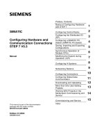
SIEMENS - simatic PID temperature control potx
Bạn đang xem bản rút gọn của tài liệu. Xem và tải ngay bản đầy đủ của tài liệu tại đây (1.59 MB, 102 trang )
s
Preface, Contents
Introduction
1
Continuous Temperature
Controller FB 58 "TCONT_CP"
2
Controller Tuning in FB 58
"TCONT_CP"
3
Temperature Step Controller
FB59 "TCONT_S"
4
Getting Started
5
Examples for the Temperature
Controllers
6
Appendix
A
Abbreviations and Acronyms
B
Index
SIMATIC
PID Temperature Control
Manual
Edition 12/2003
A5E00125039-02
Copyright © Siemens AG 2001-2003 All rights reserved
The reproduction, transmission or use of this document or its
contents is not permitted without express written authority.
Offenders will be liable for damages. All rights, including rights
created by patent grant or registration of a utility model or design,
are reserved.
Siemens AG
Bereich Automation and Drives
Geschaeftsgebiet Industrial Automation Systems
Postfach 4848, D- 90327 Nuernberg
Disclaimer of Liability
We have checked the contents of this manual for agreement with
the hardware and software described. Since deviations cannot be
precluded entirely, we cannot guarantee full agreement. Howeve
r,
the data in this manual are reviewed regularly and any necessary
corrections included in subsequent editions. Suggestions for
improvement are welcomed.
©Siemens AG 2001-2003
Technical data subject to change.
Siemens Aktiengesellschaft A5E00125039-02
Safety Guidelines
This manual contains notices intended to ensure personal safety, as well as to protect the products and
connected equipment against damage. These notices are highlighted by the symbols shown below and
graded according to severity by the following texts:
!
Danger
indicates that death, severe personal injury or substantial property damage will result if proper
precautions are not taken.
!
Warning
indicates that death, severe personal injury or substantial property damage can result if proper
precautions are not taken.
!
Caution
indicates that minor personal injury can result if proper precautions are not taken.
Caution
indicates that property damage can result if proper precautions are not taken.
Notice
draws your attention to particularly important information on the product, handling the product, or to a
particular part of the documentation.
Qualified Personnel
Only qualified personnel should be allowed to install and work on this equipment. Qualified persons
are defined as persons who are authorized to commission, to ground and to tag circuits, equipment, and
systems in accordance with established safety practices and standards.
Correct Usage
Note the following:
!
Warning
This device and its components may only be used for the applications described in the catalog or the
technical description, and only in connection with devices or components from other manufacturers
which have been approved or recommended by Siemens.
This product can only function correctly and safely if it is transported, stored, set up, and installed
correctly, and operated and maintained as recommended.
Trademarks
SIMATIC®, SIMATIC HMI® and SIMATIC NET® are registered trademarks of SIEMENS AG.
Third parties using for their own purposes any other names in this document which refer to trademarks
might infringe upon the rights of the trademark owners.
PID Temperature Control
A5E00125039-02
iii
Preface
Purpose of the Manual
This manual supports you when you work with the temperature controller block
from the Standard Library > PID Control. It will familiarize you with the functions
of the controller blocks and, in particular, with tuning the controller and working with
the user interface in which you set the parameters for the blocks. There is an
online help system for both the blocks and the user interface that supports you
when setting the parameters of the blocks.
This manual is intended for qualified personnel involved in programming,
configuration, commissioning, and servicing of programmable controllers.
We recommend that you spend some time studying the "Examples of Temperature
Controllers" in Chapter 6. These examples will help you to understand the
application of temperature controllers quickly and simply.
Basic Knowledge Required
To understand this manual, you should be familiar with automation engineering
and know the basics of closed-loop control.
You should also be familiar with using computers or similar tools (for example
programming devices) with the Windows 95/98/NT/2000 or Me operating system.
Since PID Temperature Control is used in conjunction with the STEP 7 basic
software, you should be familiar with working with the basic software as described
in the "Programming with STEP 7 V5.1" manual.
Scope of the Manual
This manual applies to the temperature controllers of the Standard Library > PID
Control of the STEP 7 programming software, Version V5.1 Service Pack 3 and
higher.
Preface
PID Temperature Control
iv A5E00125039-02
STEP 7 Documentation Packages
This manual is part of the STEP 7 Basic Information documentation package.
Manuals Purpose Order Number
STEP 7 Basic Information with
• Working with STEP 7 V5.1
Getting Started
• Programming with STEP 7
V5.1
• Configuring Hardware and
Communication
Connections,
STEP 7 V5.1
• From S5 to S7, Convertor
Manual
Basic information for technical
personnel describing the
methods of implementing
control tasks with STEP 7 and
S7-300/400.
6ES7810-4CA05-8BA0
STEP 7 Reference with
• Ladder Logic (LAD) /
Function Block Diagram
(FBD) / Statement List
(STL) for S7-300/400
manuals
• Standard and System
Functions for
S7-300/400
Provides reference information
and describes the programming
languages LAD, FBD, and STL
and standard and system
functions extending the scope
of STEP 7 basic information.
6ES7810-4CA05-8BR0
Elect. manual
• PID Temperature Control
This manual describes the
temperature controllers of the
Standard Library > PID Control.
Part of the STEP 7
software package
Online Help Systems Purpose Order Number
Help on STEP 7 Basic information on
programming and configuring
hardware with STEP 7 in the
form of an online help.
Part of the STEP 7
software package
Reference help systems for
• LAD/FBD/STL
• SFBs/SFCs
• Organization blocks
• PID Temperature Control
Context-sensitive reference
information
Part of the STEP 7
software package
Further Closed-Loop Control Products in SIMATIC S7
• SIMATIC S7 User Manuals: Standard PID Control, Modular PID Control,
PID Self-Tuner, FM355/455 PID Control
• Jürgen Müller, "Regeln mit SIMATIC - Praxisbuch für Regelungen mit
SIMATIC S7 und PCS7" published by MCI Publicis Verlag
ISBN 3-89578-147-9 (German only)
Preface
PID Temperature Control
A5E00125039-02
v
Further Support
If you have any technical questions, please get in touch with your Siemens
representative or agent responsible.
You will find your contact person at:
/>
Training Centers
Siemens offers a number of training courses to familiarize you with the SIMATIC
S7 automation system. Please contact your regional training center or our central
training center in D 90327 Nuremberg, Germany for details:
Telephone: +49 (911) 895-3200.
Internet:
SIMATIC Documentation on the Internet
Documentation is available free of charge on the Internet at:
/>
Here, you can use the Knowledge Manager to locate the documentation you
require quickly. If you have questions or suggestions regarding the documentation,
a "Documentation" conference is available in the Internet Forum.
Preface
PID Temperature Control
vi A5E00125039-02
A&D Technical Support
Worldwide, available 24 hours a day:
Beijing
Peking
Nuernberg
Johnson City
Worldwide (Nuernberg)
Technical Support
24 hours a day, 365 days a year
Phone: +49 (180) 5050-222
Fax: +49 (180) 5050-223
E-Mail: adsupport@
siemens.com
GMT: +1:00
Europe / Africa (Nuernberg)
Authorization
Local time: Mon Fri. 8:00 to 5:00 PM
Phone: +49 (180) 5050-222
Fax: +49 (180) 5050-223
E-Mail: adsupport@
siemens.com
GMT: +1:00
United States (Johnson City)
Technical Support and
Authorization
Local time: Mon Fri. 8:00 to 5:00 PM
Phone: +1 (423) 262 2522
Fax: +1 (423) 262 2289
E-Mail: simatic.hotline@
sea.siemens.com
GMT: -5:00
Asia / Australia (Beijing)
Technical Support and
Authorization
Local time: Mon Fri. 8:00 to 5:00 PM
Phone: +86 10 64 75 75 75
Fax: +86 10 64 74 74 74
E-Mail: adsupport.asia@
siemens.com
GMT: +8:00
The languages of the SIMATIC Hotlines and the authorization hotline are generally German and English.
Preface
PID Temperature Control
A5E00125039-02
vii
Service & Support on the Internet
In addition to our documentation, we offer our Know-how online on the internet at:
/>
where you will find the following:
• The newsletter, which constantly provides you with up-to-date information on
your products.
• The right documents via our Search function in Service & Support.
• A forum, where users and experts from all over the world exchange their
experiences.
• Your local representative for Automation & Drives.
• Information on field service, repairs, spare parts and more under "Services".
Preface
PID Temperature Control
viii A5E00125039-02
PID Temperature Control
A5E00125039-02
ix
Contents
1 Introduction 1-1
1.1 FB 58 "TCONT_CP" 1-3
1.2 FB59 "TCONT_S" 1-4
2 Continuous Temperature Controller FB 58 "TCONT_CP" 2-1
2.1 Controller Section 2-1
2.1.1 Forming the Error 2-1
2.1.2 PID Algorithm 2-4
2.1.3 Calculating the Manipulated Variable 2-6
2.1.4 Saving and Reloading Controller Parameters 2-9
2.2 Pulse Generator PULSEGEN (PULSE_ON) 2-11
2.3 Block Diagram 2-13
2.4 Including the Function Block in the User Program 2-14
2.4.1 Calling the Controller Block 2-14
2.4.2 Call without Pulse Generator (continuous controller) 2-15
2.4.3 Call with Pulse Generator (pulse controller) 2-15
2.4.4 Initialization 2-18
3 Controller Tuning in FB 58 "TCONT_CP" 3-1
3.1 Introduction 3-1
3.2 Process Types 3-2
3.3 Area of Application 3-3
3.4 The Phases of Controller Tuning 3-4
3.5 Preparations 3-6
3.6 Starting Tuning (Phase 1 -> 2) 3-8
3.7 Searching for the Point of Inflection (Phase 2)
and Calculating the Control Parameters (Phase 3, 4, 5) 3-10
3.8 Checking the Process Type (Phase 7) 3-10
3.9 Result of the Tuning 3-11
3.10 Tuning Stopped by the Operator 3-11
3.11 Error Situations and Remedies 3-12
3.12 Manual Fine Tuning in Control Mode 3-16
3.13 Parallel Tuning of Control Channels 3-19
4 Temperature Step Controller FB59 "TCONT_S" 4-1
4.1 Controller Section 4-1
4.1.1 Forming the Error 4-1
4.1.2 PI Step Controller Algorithm 4-4
4.2 Block Diagram 4-5
4.3 Including the Function Block in the User Program 4-6
4.3.1 Calling the Controller Block 4-6
4.3.2 Sampling Time 4-7
4.3.3 Initialization 4-7
5 Getting Started 5-1
Contents
PID Temperature Control
x A5E00125039-02
6 Examples for the Temperature Controllers 6-1
6.1 Introduction 6-1
6.2 Example with FB 58 "TCONT_CP" (pulse control) 6-2
6.3 Samples for FB 58 "TCONT_CP"
with Short Pulse Generator Sampling Time 6-6
6.4 Sample for FB 58 "TCONT_CP" (Continuous) 6-7
6.5 Sample for FB 59 "TCONT_S" (Step Controller) 6-11
A Appendix A-1
A.1 Technical Specifications A-1
A.2 Execution Times A-1
A.3 DB Assignment A-2
A.3.1 Instance DB for FB 58 "TCONT_CP" A-2
A.3.2 Instance DB for FB 59 "TCONT_S" A-13
A.4 List of Possible Messages during Tuning A-17
B Abbreviations and Acronyms B-1
Index
PID Temperature Control
A5E00125039-02
1-1
1 Introduction
Product Structure of "PID Temperature Control"
PID Temperature Control
S7-300/400
Parameter assign.
Function blocks
FB58 "TCONT_CP "
FB59 "TCONT_S "
Electronic Manual
Examples
Online help
Parameter
assignment
User interface
After you have installed STEP 7, the various parts of STEP 7 PID Temperature
Control are located in the following folders:
• SIEMENS\STEP7\S7LIBS\: FBs
• SIEMENS\STEP7\S7WRT\: parameter assignment user interface, readme,
online help
• SIEMENS\STEP7\EXAMPLES\: sample programs
• SIEMENS\STEP7\MANUAL\: manual
Introduction
PID Temperature Control
1-2 A5E00125039-02
Function Blocks
The "Standard Library PID Control" contains two temperature controllers:
1. FB 58 "TCONT_CP":
Temperature controller for actuators with a continuous or pulsed input signal.
This controller block also includes a self-tuning function for the PI/PID
parameters.
2. FB 59 "TCONT_S":
Temperature step controller for actuators with an integral component such as a
positioning motor.
The control blocks are purely software controllers in which a block includes the
entire functionality of the controller. The data required for cyclic calculation are
stored in the corresponding instance data blocks.
Parameter Assignment User Interface
You set the parameters for the controller and tune it using the parameter
assignment user interface. The parameter settings are stored in the relevant
instance DB. You can start the parameter assignment user interface by double-
clicking on the relevant instance data block.
Online Help
You will find a description of the parameter assignment user interface and the
function blocks in the online help systems.
Opening the Readme File
The readme file contains the latest information on the software you have received.
You will find this file in the Windows Start menu.
Introduction
PID Temperature Control
A5E00125039-02
1-3
1.1 FB 58 "TCONT_CP"
FB 58 "TCONT_CP" is used to control temperature processes with continuous or
pulsed control signals. You can set parameters to enable or disable subfunctions of
the PID controller and adapt it to the process. These settings can be made simply
with the parameter assignment tool. You start this within a project by double-
clicking on the instance DB in the SIMATIC Manager. You can open the electronic
manual as follows:
Start > Simatic > Documentation > English > PID Temperature Control.
Application
The functionality is based on the PID control algorithm with additional functions for
temperature processes. The controller supplies analog manipulated values and
pulse-duration modulated actuating signals. The controller outputs signals to one
actuator; in other words, with one controller, you can either heat or cool but not
both.
Using the Controller in a Heating or Cooling Process
FB TCONT_CP can be used either purely for heating or purely for cooling. If you
use the block for cooling, GAIN must be assigned a negative value. This inversion
of the controller means that, for example if the temperature rises, the manipulated
variable LMN and with it the cooling effort is increased.
Outline of the Structure
PID Temperature controller
•
Control zone
Pulse generator
Manipulated variable
LMN
Setpoint
SP_INT
QPULSE
Controller tuning
•
PI/PID parameters
Process value
PV_PER
PV_IN
Control zone width
Sampling time
Improved
control response
Actuating signal
Introduction
PID Temperature Control
1-4 A5E00125039-02
Description
Apart from the functions in the setpoint and process value branches, the FB
implements a complete PID temperature controller with a continuous and binary
manipulated variable output. To improve the control response with temperature
processes, the block includes a control zone and reduction of the P-action if there
is a setpoint step change.
The block can set the PI/PID parameters itself using the controller tuning function.
1.2 FB59 "TCONT_S"
FB59 "TCONT_S" is used to control technical temperature processes with binary
controller output signals for integrating actuators on the SIMATIC S7
programmable controllers. By setting parameters, subfunctions of the PI step
controller can be activated or deactivated and the controller adapted to the
process. These settings can be made simply in the parameter assignment user
interface. You start this within a project by double-clicking on the instance DB in the
SIMATIC Manager. You can open the electronic manual as follows:
Start > Simatic > Documentation > English > PID Temperature Control.
Application
The functionality is based on the PI control algorithm of the sampling controller.
This is supplemented by the functions for generating the binary output signal from
the analog actuating signal.
You can also use the controller in a cascade control as a secondary position
controller. You specify the actuator position via the setpoint input SP_INT. In this
case, you must set the process value input and the parameter TI (integral time) to
zero. An application might be, for example, temperature control with heating power
control using pulse-break activation and cooling control using a butterfly valve. To
close the valve completely, the manipulated variable (ER*GAIN) should be
negative.
Description
Apart from the functions in the process variable branch, FB 59 "TCONT_S"
implements a complete PI controller with binary manipulated value output and the
option of influencing the controller output signals manually. The step controller
operates without a position feedback signal.
PID Temperature Control
A5E00125039-02
2-1
2 Continuous Temperature Controller FB 58
"TCONT_CP"
2.1 Controller Section
2.1.1 Forming the Error
The schematic below is a block diagram illustrating how the error is formed:
SP_INT
PV_IN
PV_PER
CRP_IN
PER_MODE
PV_NORM
PV_FAC,
PV_OFFS
*0,1
0
C
*0,01
0
C
%
1
0
PVPER_ON
PV
DEADBAND
DEADB_W
ER
+
Parameter assignment user interface
Parameter assignment u ser interface, FB call interface
FB call interface
Setpoint Branch
The setpoint is entered at input SP_INT in floating-point format as a physical value
or percentage. The setpoint and process value used to form the error must have
the same unit.
Process Value Options (PVPER_ON)
Depending on PVPER_ON, the process value can be acquired in the peripheral
(I/O) or floating-point format.
PVPER_ON Process Value Input
TRUE The process value is read in via the analog peripheral I/Os (PIW xxx)
at input PV_PER.
FALSE The process value is acquired in floating-point format at input PV_IN.
Continuous Temperature Controller FB 58 "TCONT_CP"
PID Temperature Control
2-2 A5E00125039-02
Process Value Format Conversion CRP_IN (PER_MODE)
The CRP_IN function converts the peripheral value PV_PER to a floating-point
format depending on the switch PER_MODE according to the following rules:
PER_MODE Output of
CRP_IN
Analog Input Type Unit
0 PV_PER * 0.1 Thermoelements; PT100/NI100; standard °C;
°F
1 PV_PER * 0.01 PT100/NI100; climate; °C;
°F
2 PV_PER *
100/27648
Voltage/current %
Process Value Normalization PV_NORM (PF_FAC, PV_OFFS)
The PV_NORM function calculates the output of CRP_IN according to the following
rule:
"Output of PV_NORM" = "Output of CPR_IN" * PV_FAC + PV_OFFS
It can be used for the following purposes:
• Process value correction with PV_FAC as the process value factor and
PV_OFFS as the process value offset.
• Normalization of temperature to percentage
You want to enter the setpoint as a percentage and must now convert the
measured temperature value to a percentage.
• Normalization of percentage to temperature
You want to enter the setpoint in the physical temperature unit and must now
convert the measured voltage/current value to a temperature.
Calculation of the parameters:
• PV_FAC = range of PV_NORM/range of CRP_IN;
• PV_OFFS = LL(PV_NORM) - PV_FAC * LL(CRP_IN);
where LL is the lower limit
With the default values (PV_FAC = 1.0 and PV_OFFS = 0.0), normalization is
disabled. The effective process value is output at the PV output.
Note
With pulse control, the process value must be transferred to the block in the fast
pulse call (reason: mean value filtering). Otherwise, the control quality can
deteriorate.
Continuous Temperature Controller FB 58 "TCONT_CP"
PID Temperature Control
A5E00125039-02
2-3
Example of Process Value Normalization
If you want to enter the setpoint as a percentage, and you have a temperature
range of -20 to 85 °C applied to CRP_IN, you must normalize the temperature
range as a percentage.
The schematic below shows an example of adapting the temperature range
-20 to 85 °C to an internal scale of 0 to 100 %:
PV_NORM [%]
100
75
50
25
-20
20 40 60 80 85
[°c]CRP_IN
PV_OFFS = 0-0.9524*(-20)
PV_FAC = 100/(85-(-20))
= 0.9524
= 19.05
Forming the Error
The difference between the setpoint and process value is the error before the
deadband.
The setpoint and process value must exist in the same unit.
Deadband (DEADB_W)
To suppress a small constant oscillation due to the manipulated variable
quantization (for example in pulse duration modulation with PULSEGEN) a
deadband (DEADBAND) is applied to the error. If DEADB_W = 0.0, the deadband
is deactivated. The effective error is indicated by the ER parameter.
ER
SP_INT - PV
ER = (SP_INT - PV) - DEAD_WER = (SP_INT - PV) + DEAD_W
DEADB_W
Continuous Temperature Controller FB 58 "TCONT_CP"
PID Temperature Control
2-4 A5E00125039-02
2.1.2 PID Algorithm
The schematic below is the block diagram of the PID algorithm:
X
ER
INT
DIF
+
+
LMN_P
LMN_I
LMN_D
SP_INT
f()
LMN_Sum
GAIN
PFAC_SP
TD, D_F
INT_HPOS
INT_HNEG
TI, I_ITL_ON,
I_ITLVAL
DISV
Parameter assignment user interface
Parameter assignment user interface, FB call interface
FB call interface
PID Algorithm (GAIN, TI, TD, D_F)
The PID algorithm operates as a position algorithm. The proportional, integral
(INT), and derivative (DIF) actions are connected in parallel and can be activated
or deactivated individually. This allows P, PI, PD, and PID controllers to be
configured.
The controller tuning supports PI and PID controllers. Controller inversion is
implemented using a negative GAIN (cooling controller).
If you set TI and TD to 0.0, you obtain a pure P controller at the operating point.
The step response in the time range is:
Where:
LMN_Sum(t) is the manipulated variable in automatic mode of the controller
ER
(0) is the step change of the normalized error
GAIN is the controller gain
TI is the integral time
TD is the derivative time
D_F is the derivative factor
)
e
TD/D_F
t
*D_Ft*
TI
1
ER(0)(1*GAINLMN_Sum(t)
−
++=
Continuous Temperature Controller FB 58 "TCONT_CP"
PID Temperature Control
A5E00125039-02
2-5
ER
(t)
GAIN * ER
(0)
GAIN * ER
(0)
ER
LMN_Sum(t)
t
TD / D_F
LMN_Sum
TI
GAIN * D_F ER*
Integrator (TI, I_ITL_ON, I_ITLVAL)
In the manual mode, it is corrected as follows: LMN_I = LMN - LMN_P - DISV.
If the manipulated variable is limited, the I-action is stopped. If the error moves the
I-action back in the direction of the manipulated variable range, the I-action is
enabled again.
The I-action is also modified by the following measures:
• The I-action of the controller is deactivated by TI = 0.0
• Weakening the P-action when setpoint changes occur
• Control zone
• Online modification of the manipulated value limits
Weakening the P-Action when Setpoint Changes Occur (PFAC_SP)
To prevent overshoot, you can weaken the P-action using the "proportional factor
for setpoint changes" parameter (PFAC_SP). Using PFAC_SP, you can select
continuously between 0.0 and 1.0 to decide the effect of the P-action when the
setpoint changes:
• PFAC_SP=1.0: P-action has full effect if the setpoint changes
• PFAC_SP=0.0: P-action has no effect if the setpoint changes
The weakening of the P-action is achieved by compensating the I-action.
Derivative action element (TD, D_F)
• The D-action of the controller is deactivated with TD = 0.0.
• If the D-action is active, the following relationship should apply:
TD
≥ 0.5 * CYCLE * D_F
Continuous Temperature Controller FB 58 "TCONT_CP"
PID Temperature Control
2-6 A5E00125039-02
Parameter Settings of a P or PD Controller with Operating Point
In the user interface, deactivate the I-action (TI = 0.0) and possible also the D-
action (TD = 0.0). Then make the following parameter settings:
• I_ITL_ON = TRUE
• I_ITLVAL = operating point;
Feedforward Control (DISV)
A feedforward variable can be added at the DISV input.
2.1.3 Calculating the Manipulated Variable
The schematic below is the block diagram of the manipulated variable calculation:
LMN_Sum
0
1
CRP_OUT
%
LMN_NORM
ER
LmnN
MAN
MAN_ON
CONZ_ON,
CON_ZONE
QLMN_HLM
QLMN_LLM
LMN_HLM
LMN_LLM
LMN_FAC,
LMN_OFFS
LMN
LMN_PER
CONZONE
LMNLIMIT
PULSEGEN
Parameter assignment user interface, FB call interface
FB call interface
Parameter assignment user interface
Control Zone (CONZ_ON, CON_ZONE)
If CONZ_ON = TRUE, the controller operates with a control zone. This means that
the controller operates according to the following algorithm:
• If PV exceeds SP_INT by more than CON_ZONE, the value LMN_LLM is
output as the manipulated variable (controlled closed-loop).
• If PV falls below SP_INT by more than CON_ZONE, the value LMN_HLM is
output as the manipulated variable (controlled closed-loop).
• If PV is within the control zone (CON_ZONE), the manipulated variable takes
its value from the PID algorithm LMN_Sum (automatic closed-loop control).
Note
The changeover from controlled closed-loop to automatic closed-loop control
takes into account a hysteresis of 20% of the control zone.
Continuous Temperature Controller FB 58 "TCONT_CP"
PID Temperature Control
A5E00125039-02
2-7
SP_INT
Lower control zone
Upper control zone
Time
SP_INT + CON_ZONE
SP_INT - CON_ZONE
Do not heat with LMN = LMN_LLM
Heat with LMN = LMN_HLM
Temperature
Note
Before activating the control zone manually, make sure that the control zone
band is not too narrow. If the control zone band is too small, oscillations will occur
in the manipulated variable and process variable.
Advantage of the Control Zone
When the process value enters the control zone, the D-action causes an extremely
fast reduction of the manipulated variable. This means that the control zone is only
useful when the D-action is activated. Without a control zone, basically only the
reducing P-action would reduce the manipulated variable. The control zone leads
to faster settling without overshoot or undershoot if the output minimum or
maximum manipulated variable is a long way from the manipulated variable
required for the new operating point.
Manual Value Processing (MAN_ON, MAN)
You can switch over between manual and automatic operation. In the manual
mode, the manipulated variable is corrected to a manual value.
The integral action (INT) is set internally to LMN - LMN_P - DISV and the derivative
action (DIF) is set to 0 and synchronized internally. Switching over to automatic
mode is therefore bumpless.
Note
During tuning, the MAN_ON parameter is not effective.
Continuous Temperature Controller FB 58 "TCONT_CP"
PID Temperature Control
2-8 A5E00125039-02
Manipulated Variable Limitation LMNLIMIT (LMN_HLM, LMN_LLM)
The value of the manipulated variable is limited to the LMN_HLM and LMN_LLM
limits by the LMNLIMIT function. If these limits are reached, this is indicated by the
message bits QLMN_HLM and QLMN_LLM.
If the manipulated variable is limited, the I-action is stopped. If the error moves the
I-action back in the direction of the manipulated variable range, the I-action is
enabled again.
Changing the Manipulated Variable Limits Online
If the range of the manipulated variable is reduced and the new unlimited value of
the manipulated variable is outside the limits, the I-action and therefore the value of
the manipulated variable shifts.
The manipulated variable is reduced by the same amount as the manipulated
variable limit changed. If the manipulated variable was unlimited prior to the
change, it is set exactly to the new limit (described here for the upper manipulated
variable limit).
Manipulated Variable Normalization LMN_NORM (LMN_FAC, LMN_OFFS)
The LMN_NORM function normalizes the manipulated variable according to the
following formula:
LMN = LmnN * LMN_FAC + LMN_OFFS
It can be used for the following purposes:
• Manipulated variable adaptation with LMN_FAC as manipulated variable factor
and LMN_OFFS manipulated variable offset
The value of the manipulated variable is also available in the peripheral format. The
CRP_OUT function converts the LMN floating-point value to a peripheral value
according to the following formula:
LMN_PER = LMN * 27648/100
With the default values (LMN_FAC = 1.0 and LMN_OFFS = 0.0), normalization is
disabled. The effective manipulated variable is output at output LMN.
Continuous Temperature Controller FB 58 "TCONT_CP"
PID Temperature Control
A5E00125039-02
2-9
2.1.4 Saving and Reloading Controller Parameters
The schematic below shows the block diagram:
0
1
PID_CON
PID_ON
PI_CON
MAN_ON
&
LOAD_PID
GAIN,
TI,
TD,
CONZONE
0
1
SAVE_PAR
0
1
PAR_SAVE
PFAC_SP,
GAIN,
TI,
TD,
D_F,
CONZ_ON,
CONZONE
0
1
PAR_SAVE
PFAC_SP,
GAIN,
TI,
TD,
D_F,
CONZ_ON,
CONZONE
MAN_ON
&
UNDO_PAR
Saving Controller Parameters SAVE_PAR
If the current parameter settings are usable, you can save them in a special
structure in the instance DB of FB58 "TCONT_CP" prior to making a manual
change. If you tune the controller, the saved parameters are overwritten by the
values that were valid prior to tuning.
PFAC_SP, GAIN, TI, TD, D_F, CONZ_ON and CONZONE are written to the
PAR_SAVE structure.
Reloading Saved Controller Parameters UNDO_PAR
The last controller parameter settings you saved can be activated for the controller
again using this function (in manual mode only).
Changing Between PI and PID Parameters LOAD_PID (PID_ON)
Following tuning, the PI and PID parameters are stored in the PI_CON and
PID_CON structures. Depending on PID_ON, you can use LOAD_PID in the
manual mode to write the PI or PID parameters to the effective controller
parameters.
PID parameter
PID_ON = TRUE
PI parameter
PID_ON = FALSE
• GAIN = PID_CON.GAIN
• TI = PID_CON.TI
• TD = PID_CON.TD
• GAIN = PI_CON.GAIN
• TI = PI_CON.TI
Continuous Temperature Controller FB 58 "TCONT_CP"
PID Temperature Control
2-10 A5E00125039-02
Note
• The controller parameters are only written back to the controller with
UNDO_PAR or LOAD_PID when the controller gain is not 0:
LOAD_PID copies the parameters only if the relevant GAIN is <> 0 (either of
the PI or PID parameters). This strategy takes into account the situation that
no tuning has yet been made or that PID parameters are missing. If
PID_ON = TRUE and PID.GAIN = FALSE were set, PID_ON will be set to
FALSE and the PI parameters copied.
• D_F, PFAC_SP are set to default values by the tuning. These can then be
modified by the user. LOAD_PID does not change these parameters.
• With LOAD_PID, the control zone is always recalculated
(CON_ZONE = 250/GAIN) even when CONZ_ON = FALSE is set.
Continuous Temperature Controller FB 58 "TCONT_CP"
PID Temperature Control
A5E00125039-02
2-11
2.2 Pulse Generator PULSEGEN (PULSE_ON)
The PULSEGEN function converts the analog manipulated variable value LmnN to
a train of pulses with the period PER_TM using pulse duration modulation.
PULSEGEN is activated with PULSE_ON=TRUE and is processed in the
CYCLE_P cycle.
t
QPULSE
(LmnN)
0
50
100
1
0
t
PER_TM
30
50
80
Cycle PULSEGEN = CYCLE_P
A manipulated variable value LmnN = 30 % and 10 PULSEGEN calls per PER_TM
therefore means the following:
• TRUE at output QPULSE for the first three PULSEGEN calls
(30 % of 10 calls)
• FALSE at output QPULSE for seven further PULSEGEN calls
(70 % of 10 calls)
The duration of a pulse per pulse repetition period is proportional to the
manipulated variable and is calculated as follows:
Pulse duration = PER_TM * LmnN /100
By suppressing the minimum pulse or break time, the characteristic curve of the
conversion develops doglegs in the start and end regions.
The following diagram illustrates two-step control with a unipolar manipulated
variable range (0 % to 100 %):
Duration of positive pulse
100.0 %
PER_TM
PER_TM - P_B_TM
P_B_TM
0.0 %