FUNDAMENTALS OF ELECTRICAL ENGINEERING ppt
Bạn đang xem bản rút gọn của tài liệu. Xem và tải ngay bản đầy đủ của tài liệu tại đây (13.4 MB, 766 trang )
January 11, 2008 19:13 fm Sheet number 1 Page number i magenta black
FUNDAMENTALS OF
ELECTRICAL ENGINEERING
First Edition
Giorgio Rizzoni
The Ohio State University
January 11, 2008 19:13 fm Sheet number 2 Page number ii magenta black
FUNDAMENTALS OF ELECTRICAL ENGINEERING
Published by McGraw-Hill, a business unit of The McGraw-Hill Companies, Inc., 1221 Avenue of the Americas, New York,
NY 10020. Copyright © 2009 by The McGraw-Hill Companies, Inc. All rights reserved. No part of this publication may be
reproduced or distributed in any form or by any means, or stored in a database or retrieval system, without the prior written
consent of The McGraw-Hill Companies, Inc., including, but not limited to, in any network or other electronic storage or
transmission, or broadcast for distance learning.
Some ancillaries, including electronic and print components, may not be available to customers outside the
United States.
This book is printed on acid-free paper.
1234567890VNH/VNH098
ISBN 978–0–07–338037–7
MHID 0–07–338037–7
Global Publisher: Raghothaman Srinivasan
Director of Development: Kristine Tibbetts
Developmental Editor: Darlene M. Schueller
Senior Project Manager: Sheila M. Frank
Lead Production Supervisor: Sandy Ludovissy
Lead Media Project Manager: Judi David
Designer: Laurie B. Janssen
Cover/Interior Designer: Ron Bissell
(USE) Cover Image: Kevin Ponziani, Buckeye Bullet 2 team member and ECE student at Ohio State,
Getty Images RF
Lead Photo Research Coordinator: Carrie K. Burger
Compositor: Newgen
Typeface: 10/12 Times Roman
Printer: Von Hoffmann Press
Part Openers: 1,2: © PhotoDisc RF/Getty; 3: Courtesy Ford Motor Company.
Library of Congress Cataloging-in-Publication Data
Rizzoni, Giorgio.
Fundamentals of electrical engineering / Giorgio Rizzoni. – 1st ed.
p. cm.
Includes index.
ISBN 978–0–07–338037–7 — ISBN 0–07–338037–7 (hard copy : alk. paper) 1. Electric engineering. I. Title.
TK146.R4725 2009
621.3–dc22
2008000852
In memoria di
mamma
www.mhhe.com
January 11, 2008 19:13 fm Sheet number 3 Page number iii magenta black
iii
About the Author
iorgioRizzoni,TheFordMotorCompanyChair ofElectroMechanicalSystems,
received the B.S., M.S., and Ph.D. degrees, all in electrical engineering, from
the University of Michigan. He is currently a professor of mechanical and
electrical engineering at The Ohio State University, where he teaches under-
graduate courses in system dynamics, measurements, and mechatronics and graduate
courses in automotive power train modeling and control, hybrid vehicle modeling
and control, and system fault diagnosis.
Dr. Rizzoni has been involved in the development of innovative curricula
and educational programs throughout his career. At the University of Michigan, he
developed a new laboratory and curriculum for the circuits and electronics engineer-
ing service course for non–electrical engineering majors. At Ohio State, he has been
involved in the development of undergraduate and graduate curricula in mechatronic
systems with funding provided, in part, by the National Science Foundation through
an interdisciplinary curriculum development grant. The present book has been pro-
foundly influenced by this curriculum development.
Professor Rizzoni has contributed to the development of a graduate curriculum
in these areas, served as the director of U.S. Department of Energy Graduate
Automotive Technology Education Center for Hybrid Drivetrains and Control
Systems, and is currently serving as Director of the new U.S. Department of
EnergyGraduateAutomotive TechnologyEducation Center forAdvanced Propulsion
Systems. He has developed various new courses in systems dynamics, mechatronics,
fault diagnosis, powertrain dynamics and hybrid-electric vehicles.
Since 1999, Dr. Rizzoni has served as director of the Ohio State University
Center forAutomotive Research, an interdisciplinary research center serving the U.S.
government and the automotive industry worldwide. The center conducts research in
areas relatedto vehicle safety,energyefficiency,environmental impact, andpassenger
comfort. Dr. Rizzoni has published more than 200 papers in peer-reviewed journals
and conference proceedings, and he has received a number of recognitions, including
a 1991 NSF Presidential Young Investigator Award.
Dr. Rizzoni is a Fellow of IEEE, a Fellow of SAE, and a member of ASME
and ASEE; he has served as an Associate Editor of the ASME Journal of Dynamic
Systems, Measurements, and Control (1993to 1998) and of the IEEE Transactions on
Vehicular Technology (1988 to 1998). He has also served as Guest Editor of Special
Issues of the IEEE Transactions on Control System Technology, of the IEEE Control
Systems Magazine, and of Control Engineering Practice; Dr. Rizzoni is a past Chair
of the ASME Dynamic Systems and Control Division, and has served as Chair of
the Technical Committee on Automotive Control for the International Federation of
Automatic Control (IFAC).
GiorgioRizzoniistheOhio StateUniversitySAEstudentbranchfacultyadviser,
and has led teams of electrical and mechanical engineering students through the
development of an electric vehicle that established various land speed records in
2003 and 2004. He has more recently led a team of students to the development of a
hydrogen fuel cell electric land speed record vehicle, the Buckeye Bullet 2 (see cover
and inside coverpage). He is also coadviser of the Ohio State University FutureTruck
and Challenge-X hybrid-electric vehicle competition teams sponsored by the U.S.
Department of Energy, and by General Motors and Ford.
January 11, 2008 19:13 fm Sheet number 4 Page number iv magenta black
iv
Contents
Preface vi
Chapter 1 Introduction to Electrical
Engineering 1
1.1
Electrical Engineering 2
1.2 Fundamentals of Engineering Exam Review 4
1.3 System of Units 5
1.4 Special Features of This Book 5
PART I CIRCUITS 8
Chapter 2 Fundamentals of Electric
Circuits 9
2.1
Definitions 10
2.2 Charge, Current, and Kirchhoff’s Current
Law 14
2.3 Voltage and Kirchhoff’s Voltage Law 20
2.4 Electric Power and Sign Convention 24
2.5 Circuit Elements and Their i-v
Characteristics 28
2.6 Resistance and Ohm’s Law 29
2.7
Practical Voltage and Current Sources 44
2.8 Measuring Devices 45
Chapter 3 Resistive Network
Analysis 63
3.1
Network Analysis 64
3.2 The Node Voltage Method 65
3.3 The Mesh Current Method 75
3.4 Node and Mesh Analysis With Controlled
Sources 82
3.5 The Principle of Superposition 87
3.6 One-Port Networks and Equivalent Circuits 90
3.7
Maximum Power Transfer 106
3.8 Nonlinear Circuit Elements 110
Chapter 4 AC Network Analysis 129
4.1
Energy Storage (Dynamic) Circuit
Elements 130
4.2 Time-Dependent Signal Sources 145
4.3 Solution of Circuits Containing Energy Storage
Elements (Dynamic Circuits) 150
4.4 Phasor Solution of Circuits With Sinusoidal
Excitation 153
Chapter 5 Transient Analysis 177
5.1
Transient Analysis 178
5.2 Writing Differential Equations for Circuits
Containing Inductors and Capacitors 179
5.3 DC Steady-State Solution of
Circuits Containing Inductors and
Capacitors—Initial and Final Conditions 184
5.4
Transient Response of First-Order Circuits 190
5.5 Transient Response of Second-Order
Circuits 209
Chapter 6 Frequency Response
and System Concepts 243
6.1
Sinusoidal Frequency Response 244
6.2 Filters 249
6.3
Bode Plots 265
Chapter 7 AC Power 279
7.1
Power in AC Circuits 280
7.2 Complex Power 287
7.3 Transformers 303
7.4 Three-Phase Power 313
7.5 Residential Wiring; Grounding
and Safety 321
7.6 Generation and Distribution
of AC Power 325
PART II ELECTRONICS 340
Chapter 8 Operational
Amplifiers 341
8.1
Ideal Amplifiers 342
8.2 The Operational Amplifier 344
8.3 Active Filters 366
8.4
Integrator and Differentiator Circuits 372
8.5 Physical Limitations of Operational
Amplifiers 374
Chapter 9 Semiconductors
and Diodes 407
9.1
Electrical Conduction in Semiconductor
Devices 408
9.2 The pn Junction and the Semiconductor
Diode 410
January 11, 2008 19:13 fm Sheet number 5 Page number v magenta black
Contents v
9.3 Circuit Models for the Semiconductor
Diode 413
9.4 Rectifier Circuits 431
9.5 DC Power Supplies, Zener Diodes,
and Voltage Regulation 436
Chapter 10 Bipolar Junction
Transistors: Operation, Circuit
Models, and Applications 453
10.1
Transistors as Amplifiers and Switches 454
10.2 Operation of the Bipolar Junction
Transistor 456
10.3 BJT Large-Signal Model 462
10.4 Selecting an Operating Point for a BJT 470
10.5 BJT Switches and Gates 478
Chapter 11 Field-Effect Transistors:
Operation, Circuit Models, and
Applications 491
11.1
Classification of Field-Effect
Transistors 492
11.2 Overview of Enhancement-Mode
Mosfets 492
11.3 Biasing Mosfet Circuits 497
11.4 Mosfet Large-Signal Amplifiers 503
11.5 Mosfet Switches 510
Chapter 12 Digital Logic
Circuits 521
12.1
Analog and Digital Signals 522
12.2 The Binary Number System 524
12.3 Boolean Algebra 531
12.4 Karnaugh Maps and Logic Design 544
12.5 Combinational Logic Modules 557
12.6 Sequential Logic Modules 562
PART III ELECTROMECHANICS 586
Chapter 13 Principles of
Electromechanics 587
13.1
Electricity and Magnetism 588
13.2 Magnetic Circuits 598
13.3 Magnetic Materials and B-H Curves 609
13.4 Transformers 611
13.5 Electromechanical Energy Conversion 615
Chapter 14 Introduction to Electric
Machines 645
14.1
Rotating Electric Machines 646
14.2 Direct-Current Machines 658
14.3 Direct-Current Generators 664
14.4 Direct-Current Motors 668
14.5 AC Machines 681
14.6 The Alternator (Synchronous Generator) 683
14.7 The Synchronous Motor 685
14.8 The Induction Motor 690
Appendix A Linear Algebra and
Complex Numbers
∗
Appendix B The Laplace
Transform
∗
Appendix C Fundamentals of
Engineering (FE) Examination
∗
Appendix D Answers to Selected
Problems 710
Index 720
∗
Appendixes A, B, and C are available online at www.mhhe.com/rizzoni
January 11, 2008 19:13 fm Sheet number 6 Page number vi magenta black
vi
Preface
he pervasive presence of electronic devices and instrumentation in all aspects of engineering design and
analysis is one of the manifestations of the electronic revolution that has characterized the second half of the
20th century. Every aspect of engineering practice, and even of everyday life, has been affected in some way
or another by electrical and electronic devices and instruments. Computers are perhaps the most obvious
manifestations of this presence. However, many other areas of electrical engineering are also important to the
practicing engineer, from mechanical and industrial engineering, to chemical, nuclear, and materials engineering,
to the aerospace and astronautical disciplines, to civil and the emerging field of biomedical engineering. Engineers
today must be able to communicate effectively within the interdisciplinary teams in which they work.
OBJECTIVES
Engineering education and engineering professional practice have seen some rather profound changes in the past
decade. The integration of electronics and computer technologies in all engineering academic disciplines and
the emergence of digital electronics and microcomputers as a central element of many engineering products and
processes have become a common theme since the conception of this book.
The principal objective of the book is to present the principles of electrical, electronic, and electromechanical
engineering to an audience composed of non–electrical engineering majors, and ranging from sophomore students
in their first required introductory electrical engineering course, to seniors, to first-year graduate students enrolled
in more specialized courses in electronics, electromechanics, and mechatronics.
A second objective is to present these principles by focusing on the important results and applications and
presenting the students with the most appropriate analytical and computational tools to solve a variety of practical
problems.
Finally, a third objective of the book is to illustrate, by way of concrete, fully worked examples, a number of
relevant applications of electrical engineering principles. These examples are drawn from the author’s industrial
research experience and from ideas contributed by practicing engineers and industrial partners.
ORGANIZATION AND CONTENT
The book is divided into three parts, devoted to circuits, electronics, and electromechanics.
Part I: Circuits
The first part of this book presents a basic introduction to circuit analysis (Chapters 2 through 7). The material
includes over 440 homework problems.
Part: II Electronics
Part II, on electronics (Chapters 8 through 12), contains a chapter on operational amplifiers, one on diodes, two
chapters on transistors—one each on BJTs and FETs, and one on digital logic circuits. The material contained in
this section is focused on basic applications of these concepts. The chapters include 320 homework problems.
Part III: Electromechanics
Part III, on electromechanics (Chapters 13 and 14), includes basic material on electromechanical transducers and
the basic operation of DC and AC machines. The two chapters include 126 homework problems.
January 11, 2008 19:13 fm Sheet number 7 Page number vii magenta black
Preface vii
FEATURES
Pedagogy
This edition contains the following pedagogical features.
•
Learning Objectives offer an overview of key chapter ideas. Each chapter opens with a list of major
objectives, and throughout the chapter the learning objective icon indicates targeted references to each
objective.
•
Focus on Methodology sections summarize important methods and procedures for the solution of
common problems and assist the student in developing a methodical approach to problem solving.
•
Clearly Illustrated Examples illustrate relevant applications of electrical engineering principles. The
examples are fully integrated with the “Focus on Methodology” material, and each one is organized
according to a prescribed set of logical steps.
•
Check Your Understanding exercises follow each example in the text and allow students to confirm their
mastery of concepts.
•
Make the Connection sidebars present analogies to students to help them see the connection of electrical
engineering concepts to other engineering disciplines.
•
Find It on the Web links included throughout the book give students the opportunity to further explore
practical engineering applications of the devices and systems that are described in the text.
Supplements
The bookincludes a wealthof supplements availableinelectronic form.These include
•
A website accompanies this text to provide students and instructors with
additional resources for teaching and learning. You can find this site at
www.mhhe.com/rizzoni. Resources on this site include
For Students:
•
Device Data Sheets
•
Learning Objectives
For Instructors:
•
PowerPoint presentation slides of important figures from the text
•
Instructor’s Solutions Manual with complete solutions (for instructors
only)
For Instructors and Students:
•
Find It on the Web links, which give students the opportunity to explore, in
greater depth, practical engineering applications of the devices and systems
that are described in the text. In addition, several links to tutorial sites extend
the boundaries of the text to recent research developments, late-breaking
science and technology news, learning resources, and study guides to help
you in your studies and research.
January 11, 2008 19:13 fm Sheet number 8 Page number viii magenta black
viii Preface
ACKNOWLEDGMENTS
This edition of the book requires a special acknowledgment for the effort put forth by my friend Tom Hartley of the
University of Akron, who has become a mentor, coach, and inspiration for me throughout this project. Professor
Hartley,whoisanextraordinaryteacher anda devoteduserofthisbook, hasbeencloselyinvolvedin thedevelopment
of this edition by suggesting topics for new examples and exercises, creating new homework problems, providing
advice and coaching through all of the revisions, and sometimes just by lifting my spirits. I look forward to many
more years of such collaborations.
This book has been critically reviewed by the following people.
•
Hussain M. Al-Rizzo, University of
Arkansas-Little Rock
•
Lisa Anneberg, Lawrence Technological
University
•
Glen Archer, Michigan Tech University
•
Sohrab Asgarpoor, University of
Nebraska-Lincoln
•
Satish Chandra, Kansas State University
•
Ezz I. El-Masry, Dalhousie University
•
Alexander Ganago, University of Michigan
•
Riadh W. Y. Habash, University of Ottawa
•
Michael Hamid, University of South Alabama
•
Vincent G. Harris, Northeastern University
•
Charles Hulme, U.S. Naval Academy
•
Jim Kearns, York College of Pennsylvania
•
Moncef Krarti, University of Colorado at
Boulder
•
Dennis F. Lovely, University of
New Brunswick
•
Gary Perks, Cal Poly University, San Luis
Obispo
•
Michael P. Polis, Oakland University
•
Raveendra K. Rao, University of Western
Ontario
•
Angela Rasmussen, University of Utah
•
James R. Rowland, University of Kansas
•
Ceeyavash (Jeff) Salehi, Southern Utah
University
•
Mulukutla S. Sarma, Northeastern
University
•
Hesham Shaalan, U.S. Merchant Marine
Academy
•
Rony Shahidain, Kentucky State University
•
Shahram Shahbazpanahi, University of
Ontario Institute of Technology
•
Constantinos Vassiliadis, Ohio
University-Athens
•
Belinda B. Wang, University of Toronto
•
Ken Warfield, Shawnee State University
•
Sean Washburn, University of North Carolina
at Chapel Hill
•
Thomas Yang, Embry-Riddle Aeronautical
University
•
Mohamed Z. Youssef, Queen’s University
The author is also grateful to Professor Robert Veillette of the University of Akron for his many useful comments
and suggestions.
Book prefaces have a way of marking the passage of time. When the first edition of Principles andApplications
of Electrical Engineering was published, the birth of our first child, Alex, was nearing. Each of the following two
editions was similarly accompanied by the births of Maria and Michael. Now that we have successfully reached
the fifth edition of Principles and Applications and the new first edition of this book (but only the third child) I am
observing that Alex is beginning to understand some of the principles exposed in this book through his passion for
the FIRST Lego League and the Lego Mindstorms robots. Through the years, our family continues to be the center
of my life, and I am grateful to Kathryn, Alessandro, Maria, and Michael for all their love.
January 11, 2008 19:13 fm Sheet number 9 Page number ix magenta black
GUIDEDTOUR
January 11, 2008 19:13 fm Sheet number 10 Page number x magenta black
x Preface
January 11, 2008 15:36 Chap01 Sheet number 1 Page number 1 magenta black
1
CHAPTER
1
INTRODUCTION TO ELECTRICAL
ENGINEERING
he aim of this chapter is to introduce electrical engineering. The chapter is
organized to provide the newcomer with a view of the different specialties
making up electrical engineering and to place the intent and organization of
the book into perspective. Perhaps the first question that surfaces in the mind
of the student approaching the subject is, Why electrical engineering? Since this book
is directed at a readership having a mix of engineering backgrounds (including elec-
trical engineering), the question is well justified and deserves some discussion. The
chapter begins by defining the various branches of electrical engineering, showing
some of the interactions among them, and illustrating by means of a practical example
how electrical engineering is intimately connected to many other engineering disci-
plines. Section 1.2 introduces the Engineer-in-Training (EIT) national examination.
In Section 1.3 the fundamental physical quantities and the system of units are defined,
to set the stage for the chapters that follow. Finally, in Section 1.4 the organization of
the book is discussed, to give the student, as well as the teacher, a sense of continuity
in the development of the different subjects covered in Chapters 2 through 14.
January 11, 2008 15:36 Chap01 Sheet number 2 Page number 2 magenta black
2 Chapter 1 Introduction to Electrical Engineering
1.1 ELECTRICAL ENGINEERING
The typical curriculum of an undergraduate electrical engineering student includes
the subjects listed in Table 1.1. Although the distinction between some of these
subjects is not always clear-cut, the table is sufficiently representative to serve our
purposes. Figure 1.1 illustrates a possible interconnection between the disciplines
of Table 1.1. The aim of this book is to introduce the non-electrical engineering
student to those aspects of electrical engineering that are likely to be most relevant
to his or her professional career. Virtually all the topics of Table 1.1 will be
touched on in the book, with varying degrees of emphasis. Example 1.1 illustrates
the pervasive presence of electrical, electronic, and electromechanical devices and
systems in a very common application: the automobile. As you read through the
examples, it will be instructive to refer to Figure 1.1 and Table 1.1.
Table 1.1
Electrical
engineering disciplines
Circuit analysis
Electromagnetics
Solid-state electronics
Electric machines
Electric power systems
Digital logic circuits
Computer systems
Communication systems
Electro-optics
Instrumentation systems
Control systems
Power
systems
Engineering
applications
Mathematical
foundations
Electric
machinery
Analog
electronics
Digital
electronics
Computer
systems
Network
theory
Logic
theory
System
theory
Physical
foundations
Electro-
magnetics
Solid-state
physics
Optics
Control
systems
Communication
systems
Instrumentation
systems
Figure 1.1
Electrical engineering disciplines
January 11, 2008 15:36 Chap01 Sheet number 3 Page number 3 magenta black
Chapter 1 Introduction to Electrical Engineering 3
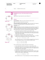
EXAMPLE 1.1
Electrical Systems in a Passenger Automobile
A familiar example illustrates how the seemingly disparate specialties of electrical engineering
actually interact to permit the operation of a very familiar engineering system: the automobile.
Figure 1.2 presents a view of electrical engineering systems in a modern automobile. Even in
older vehicles, the electrical system—in effect, an electric circuit—plays a very important part
in the overall operation. (Chapters 2 and 3 describe the basics of electric circuits.) An inductor
coil generates a sufficiently high voltage to allow a spark to form across the spark plug gap
and to ignite the air-fuel mixture; the coil is supplied by a DC voltage provided by a lead-acid
battery. (Ignition circuits are studied in some detail in Chapter 5.) In addition to providing the
energy for the ignition circuits, the battery supplies power to many other electrical components,
the most obvious of which are the lights, the windshield wipers, and the radio. Electric power
(Chapter 7) is carried from the battery to all these components by means of a wire harness,
which constitutes a rather elaborate electric circuit (see Figure 2.12 for a closer look). In recent
years, the conventional electric ignition system has been supplanted by electronic ignition;
that is, solid-state electronic devices called transistors have replaced the traditional breaker
points. The advantage of transistorized ignition systems over the conventional mechanical ones
is their greater reliability, ease of control, and life span (mechanical breaker points are subject
to wear). You will study transistors and other electronic devices in Chapters 8, 9, and 10.
Other electrical engineering disciplines are fairly obvious in the automobile.The on-board
radio receives electromagnetic waves by means of the antenna, and decodes the communication
signals to reproduce sounds and speech of remote origin; other common communication
systems that exploit electromagnetics are CB radios and the ever more common cellular
phones. But this is not all! The battery is, in effect, a self-contained 12-VDC electric power
system, providing the energy for all the aforementioned functions. In order for the battery to
have a useful lifetime, a charging system, composed of an alternator and of power electronic
devices, is present in every automobile. Electric power systems are covered in Chapter 7
and power electronic devices in Chapter 10. The alternator is an electric machine, as are the
motors that drive the power mirrors, power windows, power seats, and other convenience
features found in luxury cars. Incidentally, the loudspeakers are also electric machines! All
these devices are described in Chapters 13 and 14.
The list does not end here, though. In fact, some of the more interesting applications
of electrical engineering to the automobile have not been discussed yet. Consider computer
systems. Digital circuits are covered in Chapter 12. You are certainly aware that in the last two
Safety
Air bags and restraints
Collision warning
Security systems
Convenience
Climate control
Ergonomics
(seats, steering wheel, mirrors)
Navigation
Audio/video/ Internet/
Wireless communications
Propulsion
Engine/transmission
Integrated starter/alternator
Electric traction
42-V system
Battery management
Traction control
Ride and handling
Active/semiactive suspension
Antilock brakes
Electric power steering
Tire pressure control
Four-wheel steering
Stability control
Figure 1.2
Electrical engineering systems in the automobile
January 11, 2008 15:36 Chap01 Sheet number 4 Page number 4 magenta black
4 Chapter 1 Introduction to Electrical Engineering
decades, environmental concerns related to exhaust emissions from automobiles have led to
the introduction of sophisticated engine emission control systems. The heart of such control
systems is a type of computer called a microprocessor. The microprocessor receives signals
from devices (called sensors) that measure relevant variables—such as the engine speed, the
concentration of oxygen in the exhaust gases, the position of the throttle valve (i.e., the driver’s
demand for engine power), and the amount of air aspirated by the engine—and subsequently
computes the optimal amount of fuel and the correct timing of the spark to result in the cleanest
combustion possible under the circumstances.As the presence of computers on board becomes
more pervasive—in areas such as antilock braking, electronically controlled suspensions, four-
wheel steering systems, and electronic cruise control—communications among the various
on-board computers will have to occur at faster and faster rates. Someday in the not-so-distant
future, these communications may occur over a fiber-optic network, and electro-optics will
replace the conventional wire harness. Note that electro-optics is already present in some of
the more advanced displays that are part of an automotive instrumentation system.
Finally, today’s vehicles also benefit from the significant advances made in communi-
cation systems. Vehicle navigation systems can include Global Positioning System, or GPS,
technology, as well as a variety of communications and networking technologies, such as wire-
less interfaces (e.g., based on the “Bluetooth” standard) and satellite radio and driver assistance
systems, such as the GM “OnStar” system.
1.2 FUNDAMENTALS OF ENGINEERING
EXAM REVIEW
To become a professional engineer it is necessary to satisfy four requirements. The
first is the completion of a B.S. degree in engineering from an accredited college
or university (although it is theoretically possible to be registered without having
completed a degree). The second is the successful completion of the Fundamentals
of Engineering (FE) Examination. This is an eight-hour exam that covers general
undergraduate engineering education. The third requirement is two to four years of
engineering experience after passing the FE exam. Finally, the fourth requirement is
successful completion of the Principles and Practice of Engineering or Professional
Engineer (PE) Examination.
The FE exam is a two-part national examination, administered by the National
Council of Examiners for Engineers and Surveyors (NCEES) and given twice
a year (in April and October). The exam is divided into two four-hour sessions,
consisting of 120 questions in the four-hour morning session, and 60 questions in
the four-hour afternoon session. The morning session covers general background in
12 different areas, one of which is Electricity and Magnetism. The afternoon session
requires the examinee to choose among seven modules—Chemical, Civil, Electrical,
Environmental, Industrial, Mechanical, and Other/General engineering.
One of the aims of this book is to assist you in preparing for the Electricity
and Magnetism part of the morning session. This part of the examination consists of
approximately 9 percent of the morning session, and covers the following topics:
A. Charge, energy, current, voltage, power.
B. Work done in moving a charge in an electric field (relationship between
voltage and work).
C. Force between charges.
D. Current and voltage laws (Kirchhoff, Ohm).
E. Equivalent circuits (series, parallel).
January 11, 2008 15:36 Chap01 Sheet number 5 Page number 5 magenta black
Chapter 1 Introduction to Electrical Engineering 5
F. Capacitance and inductance.
G. Reactance and impedance, susceptance and admittance.
H. AC circuits.
I. Basic complex algebra.
Appendix C (available online) contains review of the electrical circuits portion of the
FE examination, including references to the relevant material in the book. In addition,
Appendix C also contains a collection of sample problems—some including a full
explanation of the solution, some with answers supplied separately. This material has
been derived from the author’s experience in co-teaching the FE exam preparation
course offered to Ohio State University seniors.
1.3 SYSTEM OF UNITS
This book employs the International System of Units (also called SI, from the French
Système International des Unités). SI units are commonly adhered to by virtually all
engineering professional societies. This section summarizes SI units and will serve
as a useful reference in reading the book.
SI units are based on six fundamental quantities, listed in Table 1.2. All other
units may be derived in terms of the fundamental units of Table 1.2. Since, in practice,
one often needs to describe quantities that occur in large multiples or small fractions
of a unit, standard prefixes are used to denote powers of 10 of SI (and derived) units.
These prefixes are listed in Table 1.3. Note that, in general, engineering units are
expressed in powers of 10 that are multiples of 3.
For example, 10
−4
s would be referred to as 100 ×10
−6
s, or 100 μs (or, less
frequently, 0.1 ms).
Table 1.2
SI units
Quantity Unit Symbol
Length Meter m
Mass Kilogram kg
Time Second s
Electric current Ampere A
Temperature Kelvin K
Luminous intensity Candela cd
Table 1.3
Standard prefixes
Prefix Symbol Power
atto a 10
−18
femto f 10
−15
pico p 10
−12
nano n 10
−9
micro μ 10
−6
milli m 10
−3
centi c 10
−2
deci d 10
−1
deka da 10
kilo k 10
3
mega M 10
6
giga G 10
9
tera T 10
12
1.4 SPECIAL FEATURES OF THIS BOOK
This book includes a number of special features designed to make learning easier
and to allow students to explore the subject matter of the book in greater depth, if
so desired, through the use of computer-aided tools and the Internet. The principal
features of the book are described on the next two pages.
January 11, 2008 15:36 Chap01 Sheet number 6 Page number 6 magenta black
6 Chapter 1 Introduction to Electrical Engineering
➲
Learning Objectives
1. The principal learning objectives are clearly identified at the beginning of each
chapter.
2. The symbol ➲ is used to identify definitions and derivations critical to the accom-
plishment of a specific learning objective.
3. Each example is similarly marked.
EXAMPLES
The examples in the book have also been set aside from the main text, so that they can be
easily identified. All examples are solved by following the same basic methodology: A clear
and simple problem statement is given, followed by a solution. The solution consists of several
parts: All known quantities in the problem are summarized, and the problem statement is
translated into a specific objective (e.g., “Find the equivalent resistance R”).
Next, the given data and assumptions are listed, and finally the analysis is presented. The
analysis method is based on the following principle: All problems are solved symbolically first,
to obtain more general solutions that may guide the student in solving homework problems;
the numerical solution is provided at the very end of the analysis. Each problem closes with
comments summarizing the findings and tying the example to other sections of the book.
The solution methodology used in this book can be used as a general guide to problem-
solving techniques well beyond the material taught in the introductory electrical engineering
courses. The examples in this book are intended to help you develop sound problem-solving
habits for the remainder of your engineering career.
CHECK YOUR UNDERSTANDING
Each example is accompanied by at least one drill exercise.
Answer: The answer is provided right below the exercise.
MAKE THE
CONNECTION
This feature is devoted to
helping the student make the
connection between electrical
engineering and other
engineering disciplines.
Analogies to other fields of
engineering will be found in
nearly every chapter.
FOCUS ON METHODOLOGY
Each chapter, especially the early ones, includes “boxes” titled “Focus on
Methodology.” The content of these boxes (which are set aside from the main
text) summarizes important methods and procedures for the solution of common
problems. They usually consist of step-by-step instructions, and are designed to
assist you in methodically solving problems.
January 11, 2008 15:36 Chap01 Sheet number 7 Page number 7 magenta black
Chapter 1 Introduction to Electrical Engineering 7
Find It on the Web!
The use of the Internet as a resource for knowledge and information is becoming
increasingly common. In recognition of this fact, website references have been
included in this book to give you a starting point in the exploration of the world
of electrical engineering. Typical web references give you information on electrical
engineering companies, products, and methods. Some of the sites contain tutorial
material that may supplement the book’s contents.
Website
The list of features would not be complete without a reference to the book’s website:
www.mhhe.com/rizzoni. Create a bookmark for this site now! The site is designed
to provide up-to-date additions, examples, errata, and other important information.
HOMEWORK PROBLEMS
1.1
List five applications of electric motors in the
common household.
1.2
By analogy with the discussion of electrical systems
in the automobile, list examples of applications of the
electrical engineering disciplines of Table 1.1 for each
of the following engineering systems:
a. A ship.
b. A commercial passenger aircraft.
c. Your household.
d. A chemical process control plant.
1.3
Electric power systems provide energy in a variety of
commercial and industrial settings. Make a list of
systems and devices that receive electric power in
a. A large office building.
b. A factory floor.
c. A construction site.
January 11, 2008 15:41 Chap02 Sheet number 1 Page number 8 magenta black
-
PART I
CIRCUITS
Chapter 2 Fundamentals of Electric
Circuits
Chapter 3 Resistive Network Analysis
Chapter 4 AC Network Analysis
Chapter 5 Transient Analysis
Chapter 6 Frequency Response and
System Concepts
Chapter
7 AC Power
PART I
CIRCUITS
January 11, 2008 15:41 Chap02 Sheet number 2 Page number 9 magenta black
9
CHAPTER
2
FUNDAMENTALS OF ELECTRIC
CIRCUITS
hapter 2 presents the fundamental laws that govern the behavior of electric
circuits, and it serves as the foundation to the remainder of this book. The chap-
terbegins with aseriesof definitions toacquaintthe reader withelectriccircuits;
next, the two fundamental laws of circuit analysis are introduced: Kirchhoff’s
current and voltage laws. With the aid of these tools, the concepts of electric power
and the sign convention and methods for describing circuit elements—resistors in
particular—are presented. Following these preliminary topics, the emphasis moves
to basic analysis techniques—voltage and current dividers, and to some applica-
tion examples related to the engineering use of these concepts. Examples include a
description of strain gauges, circuits for the measurements of force and other related
mechanical variables, and of the study of an automotive throttle position sensor. The
chapter closes witha briefdiscussion ofelectric measuring instruments.The following
box outlines the principal learning objectives of the chapter.
January 11, 2008 15:41 Chap02 Sheet number 3 Page number 10 magenta black
10 Chapter 2 Fundamentals of Electric Circuits
➲
Learning Objectives
1. Identify the principal elements of electric circuits: nodes, loops, meshes, branches,
and voltage and current sources. Section 2.1.
2. Apply Kirchhoff’s laws to simple electric circuits and derive the basic circuit
equations. Sections 2.2 and 2.3.
3. Apply the passive sign convention and compute the power dissipated by circuit
elements. Calculate the power dissipated by a resistor. Section 2.4.
4. Apply the voltage and current divider laws to calculate unknown variables in simple
series, parallel, and series-parallel circuits. Sections 2.5 and 2.6.
5. Understand the rules for connecting electric measuring instruments to electric
circuits for the measurement of voltage, current, and power. Sections 2.7 and 2.8.
2.1 DEFINITIONS
In this section, we formally define some variables and concepts that are used in the
remainder of the chapter. First, we define voltage and current sources; next, we define
the concepts of branch, node, loop, and mesh, which form the basis of circuit analysis.
Intuitively, an ideal source is a source that can provide an arbitrary amount of
energy. Ideal sources are divided into two types: voltage sources and current sources.
Of these, you are probably more familiar with the first, since dry-cell, alkaline, and
lead-acid batteries are all voltage sources (they are not ideal, of course). You might
have to think harder to come up with a physical example that approximates the
behavior of an ideal current source; however, reasonably good approximations of
ideal current sources also exist. For instance, a voltage source connected in series
with a circuit element that has a large resistance to the flow of current from the source
provides a nearly constant—though small—current and therefore acts very nearly as
an ideal current source. A battery charger is another example of a device that can
operate as a current source.
MAKE THE
CONNECTION
Mechanical
(Gravitational)
Analog of Voltage
Sources
The role played by a voltage
source in an electric circuit is
equivalent to that played by
the force of gravity. Raising
a mass with respect to a
reference surface increases
its potential energy. This
potential energy can be
converted to kinetic energy
when the object moves to a
lower position relative to the
reference surface. The
voltage, or potential
difference across a voltage
source plays an analogous
role, raising the electrical
potential of the circuit, so that
current can flow, converting
the potential energy within
the voltage source to electric
power.
Ideal Voltage Sources
An ideal voltage source is an electric device that generates a prescribed voltage at
its terminals. The ability of an ideal voltage source to generate its output voltage is
not affected by the current it must supply to the other circuit elements. Another way
to phrase the same idea is as follows:
An ideal voltage source provides a prescribed voltage across its terminals
irrespective of the current flowing through it. The amount of current supplied
➲
LO1
by the source is determined by the circuit connected to it.
Figure 2.1 depicts various symbols for voltage sources that are employed
throughout this book. Note that the output voltage of an ideal source can be a function
of time. In general, the following notation is employed in this book, unless otherwise
noted. A generic voltage source is denoted by a lowercase v. If it is necessary to
emphasize that the source produces a time-varying voltage, then the notation v(t) is
January 11, 2008 15:41 Chap02 Sheet number 4 Page number 11 magenta black
Part I Circuits 11
+
_
+
_
V
s
–
–
v
s
(t)
v
s
(t)
+
–
+
–
~
v
s
(t)
+
–
v
s
(t)
+
–
v
s
(t)
General symbol
for ideal voltage
source. v
s
(t)
may be constant
(DC source).
A special case:
DC voltage
source (ideal
battery)
A special case:
sinusoidal
voltage source,
v
s
(t) = V cos ωt
Circuit
Circuit
Circuit
Figure 2.1
Ideal voltage sources
employed. Finally, a constant, or direct current, or DC, voltage source is denoted by
the uppercase character V . Note that by convention the direction of positive current
flow out of a voltage source is out of the positive terminal.
The notion of anideal voltagesource is best appreciated within the contextof the
source-load representation of electric circuits. Figure 2.2 depicts the connection of an
energysourcewitha passivecircuit(i.e.,a circuit thatcanabsorb and dissipateenergy).
Three different representations are shown to illustrate the conceptual, symbolic, and
physical significance of this source-load idea.
+
_
Car battery
Headlight
+–
i
+
–
v
R
i
i
+
–
v
Source Load
(a) Conceptual
representation
Power flow
(b) Symbolic (circuit)
representation
(c) Physical
representation
V
S
R
S
Figure 2.2
Various representations of an electrical system
In the analysis of electric circuits, we choose to represent the physical reality
of Figure 2.2(c) by means of the approximation provided by ideal circuit elements,
as depicted in Figure 2.2(b).
Ideal Current Sources
An ideal current source is a device that can generate a prescribedcurrent independent
of the circuit to which it is connected. To do so, it must be able to generate an arbitrary
voltage across its terminals. Figure 2.3 depicts the symbol used to represent ideal
current sources. By analogy with the definition of the ideal voltage source just stated,
we write that
i
S
, I
S
i
S
, I
S
Circuit
Figure 2.3
Symbol for
ideal current source
An idealcurrent source provides a prescribedcurrent to any circuit connected
to it. The voltage generated by the source is determined by the circuit connected
➲
LO1
to it.
January 11, 2008 15:41 Chap02 Sheet number 5 Page number 12 magenta black
12 Chapter 2 Fundamentals of Electric Circuits
The same uppercase and lowercase convention used for voltage sources is employed
in denoting current sources.
MAKE THE
CONNECTION
Hydraulic Analog
of Current
Sources
The role played by a current
source in an electric circuit is
very similar to that of a pump
in a hydraulic circuit. In a
pump, an internal mechanism
(pistons, vanes, or impellers)
forces fluid to be pumped
from a reservoir to a hydraulic
circuit. The volume flow rate
of the fluid q, in cubic meters
per second, in the hydraulic
circuit, is analogous to the
electrical current in the circuit.
flow flow
Discharge
high
pressure
slip
Positive Displacement Pump
Suction
low
pressure
A hydraulic pump
Left: Fixed
capacity pump.
Right: Fixed
capacity pump
with two directions
of flow.
Left: Variable
capacity pump.
Right: Variable
capacity pump
with two directions
of flow.
Pump symbols
Courtesy: Department of
Energy
Dependent (Controlled) Sources
The sources described so far have the capability of generating a prescribed voltage
or current independent of any other element within the circuit. Thus, they are termed
independent sources.There exists another category of sources,however, whoseoutput
(current or voltage) is a function of some other voltage or current in a circuit. These
are called dependent (or controlled) sources. A different symbol, in the shape of
➲
LO1
a diamond, is used to represent dependent sources and to distinguish them from
independent sources. The symbols typically used to represent dependent sources are
depicted in Figure 2.4; the table illustrates the relationship between the source voltage
or current and the voltage or current it depends on—v
x
or i
x
, respectively—which can
be any voltage or current in the circuit.
+
_
v
S
Voltage controlled voltage source (VCVS) v
S
= v
x
Current controlled voltage source (CCVS) v
S
= ri
x
Voltage controlled current source (VCCS) i
S
= gv
x
Current controlled current source (CCCS) i
S
= i
x
Source type Relationship
i
S
Figure 2.4
Symbols for dependent sources
Dependent sources are very useful in describing certain types of electronic
circuits. You will encounter dependent sources again in Chapters 8, 10, and 11, when
electronic amplifiers are discussed.
An electrical network is a collection of elements through which current flows.
The following definitions introduce some important elements of a network.
Branch
Abranch is any portion of a circuit with two terminals connected to it. A branch may
➲
LO1
consist of one or more circuit elements (Figure 2.5). In practice, any circuit element
with two terminals connected to it is a branch.
Node
A node is the junction of two or more branches (one often refers to the junction of
➲
LO1
only two branches as a trivial node). Figure 2.6 illustrates the concept. In effect,
any connection that can be accomplished by soldering various terminals together is
a node. It is very important to identify nodes properly in the analysis of electrical
networks.
It is sometimes convenient to use the concept of a supernode. A supernode
is obtained by defining a region that encloses more than one node, as shown in the
rightmost circuit of Figure 2.6. Supernodes can be treated in exactly the same way as
nodes.
January 11, 2008 15:41 Chap02 Sheet number 6 Page number 13 magenta black
Part I Circuits 13
r
m
A
Practical
ammeter
Ideal
resistor
R
v
A battery
A branch
Branch
voltage
Branch
current
+
–
a
b
i
Examples of circuit branches
Figure 2.5
Definition of a branch
Examples of nodes in practical circuits
Node a
Supernode
Node b
v
S
i
S
Node c Node a
Node b
Node
R
5
R
3
R
1
R
4
R
2
+
_
+
−
+
−
V
S1
+
−
V
S2
Figure 2.6
Definitions of node and supernode
Loop
Aloopisanyclosedconnection of branches.Various loop configurationsareillustrated
➲
LO1
in Figure 2.7.
v
S
Loop 1 Loop 2
Loop 3
R
i
S
R
1
R
2
1-loop circuit 3-loop circuit
(How many nodes in
this circuit?)
Note how two different loops
in the same circuit may
include some of the same
elements or branches.
Figure 2.7
Definition of a loop
Mesh
A mesh is a loop that does not contain other loops. Meshes are an important aid to
➲
LO1
certain analysis methods.In Figure2.7, thecircuit with loops 1, 2,and 3consists oftwo
meshes: Loops 1 and 2 are meshes, but loop 3 is not a mesh, because it encircles both
loops 1 and 2. The one-loop circuit of Figure 2.7 is also a one-mesh circuit. Figure 2.8
illustrates how meshes are simpler to visualize in complex networks than loops are.
January 11, 2008 15:41 Chap02 Sheet number 7 Page number 14 magenta black
14 Chapter 2 Fundamentals of Electric Circuits
R
3
v
S
Mesh
1
How many loops can you
identify in this four-mesh
circuit? (Answer: 15)
Mesh
2
Mesh
4
i
S
Mesh 3
R
4
R
5
R
2
R
1
+
_
Figure 2.8
Definition of a mesh
Network Analysis
The analysis of an electrical network consists of determining each of the unknown
branch currents and node voltages. It is therefore important to define all the rele-
vant variables as clearly as possible and in systematic fashion. Once the known and
unknown variables have been identified, a set of equations relating these variables is
constructed, and these are solved by means of suitable techniques.
Before introducing methods for the analysis of electrical networks, we must
formally present some important laws of circuit analysis.
2.2 CHARGE, CURRENT, AND KIRCHHOFF’S
CURRENT LAW
The earliest accounts of electricity date from about 2,500 years ago, when it was
discovered that static charge on a piece of amber was capable of attracting very light
objects, such as feathers.The word electricity originated about 600
B.C.; it comes from
elektron, which was the ancient Greek word for amber. The true nature of electricity
wasnot understood untilmuchlater, however. Following theworkofAlessandroVolta
and his invention of the copper-zinc battery, it was determined that static electricity
and the current that flows in metal wires connected to a battery are due to the same
fundamental mechanism: the atomic structure of matter, consisting of a nucleus—
neutrons and protons—surrounded by electrons. The fundamental electric quantity
is charge, and the smallest amount of charge that exists is the charge carried by an
electron, equal to
q
e
=−1.602 × 10
−19
C (2.1)
Charles Coulomb (1736–1806).
Photograph courtesy of French
Embassy, Washington, District of
Columbia.
As you can see, the amount of charge associated with an electron is rather small.
This, of course, has to do with the size of the unit we use to measure charge, the
coulomb (C), named after Charles Coulomb. However, the definition of the coulomb
leads to an appropriate unit when we define electric current, since current consists of
the flow of very large numbers of charge particles. The other charge-carrying particle
in an atom, the proton, is assigned a plus sign and the same magnitude. The charge
of a proton is
q
p
=+1.602 × 10
−19
C (2.2)
Electrons and protons are often referred to as elementary charges.
Electric current is defined as the time rate of change of charge passing through
a predetermined area. Typically, this area is the cross-sectional area of a metal