Security and Privacy Vulnerabilities of In-Car Wireless Networks: A Tire Pressure Monitoring System Case Study ppt
Bạn đang xem bản rút gọn của tài liệu. Xem và tải ngay bản đầy đủ của tài liệu tại đây (1.24 MB, 16 trang )
Security and Privacy Vulnerabilities of In-Car Wireless Networks: A Tire
Pressure Monitoring System Case Study
Ishtiaq Rouf
a
, Rob Miller
b
, Hossen Mustafa
a
, Travis Taylor
a
, Sangho Oh
b
Wenyuan Xu
a
, Marco Gruteser
b
, Wade Trappe
b
, Ivan Seskar
b ∗
a
Dept. of CSE, Univ. of South Carolina, Columbia, SC USA
{rouf, mustafah, taylort9, wyxu}@cse.sc.edu
b
WINLAB, Rutgers Univ., Piscataway, NJ USA
{rdmiller, sangho, gruteser, trappe, seskar}@winlab.rutgers.edu
Abstract
Wireless networks are being integrated into the modern
automobile. The security and privacy implications of
such in-car networks, however, have are not well under-
stood as their transmissions propagate beyond the con-
fines of a car’s body. To understand the risks associated
with these wireless systems, this paper presents a privacy
and security evaluation of wireless Tire Pressure Moni-
toring Systems using both laboratory experiments with
isolated tire pressure sensor modules and experiments
with a complete vehicle system. We show that eaves-
dropping is easily possible at a distance of roughly 40m
from a passing vehicle. Further, reverse-engineering of
the underlying protocols revealed static 32 bit identi-
fiers and that messages can be easily triggered remotely,
which raises privacy concerns as vehicles can be tracked
through these identifiers. Further, current protocols do
not employ authentication and vehicle implementations
do not perform basic input validation, thereby allowing
for remote spoofing of sensor messages. We validated
this experimentally by triggering tire pressure warning
messages in a moving vehicle from a customized soft-
ware radio attack platform located in a nearby vehicle.
Finally, the paper concludes with a set of recommenda-
tions for improving the privacy and security of tire pres-
sure monitoring systems and other forthcoming in-car
wireless sensor networks.
1 Introduction
The quest for increased safety and efficiency of au-
tomotive transportation system is leading car makers
to integrate wireless communication systems into au-
tomobiles. While vehicle-to-vehicle and vehicle-to-
infrastructure systems [22] have received much attention,
the first wireless network installed in every new vehicle
∗
This study was supported in part by the US National Science Foun-
dation under grant CNS-0845896, CNS-0845671, and Army Research
Office grant W911NF-09-1-0089.
is actually an in-vehicle sensor network: the tire pres-
sure monitoring system (TPMS). The wide deployment
of TPMSs in the United States is an outgrowth of the
TREAD Act [35] resulting from the Ford-Firestone tire
failure controversy [17]. Beyond preventing tire fail-
ure, alerting drivers about underinflated tires promises
to increase overall road safety and fuel economy because
proper tire inflation improves traction, braking distances,
and tire rolling resistance. These benefits have recently
led to similar legislation in the European Union [7] which
mandates TPMSs on all new vehicles starting in 2012.
Tire Pressure Monitoring Systems continuously mea-
sure air pressure inside all tires of passenger cars, trucks,
and multipurpose passenger vehicles, and alert drivers if
any tire is significantly underinflated. While both direct
and indirect measurement technologies exist, only direct
measurement has the measurement sensitivity required
by the TREAD Act and is thus the only one in produc-
tion. A direct measurement system uses battery-powered
pressure sensors inside each tire to measure tire pres-
sure and can typically detect any loss greater than 1.45
psi [40]. Since a wired connection from a rotating tire
to the vehicle’s electronic control unit is difficult to im-
plement, the sensor module communicates its data via a
radio frequency (RF) transmitter. The receiving tire pres-
sure control unit, in turn, analyzes the data and can send
results or commands to the central car computer over
the Controller-area Network (CAN) to trigger a warning
message on the vehicle dashboard, for example. Indirect
measurement systems infer pressure differences between
tires from differences in the rotational speed, which can
be measured using the anti-lock braking system (ABS)
sensors. A lower-pressure tire has to rotate faster to travel
the same distance as a higher-pressure tire. The disad-
vantages of this approach are that it is less accurate, re-
quires calibration by the driver, and cannot detect the si-
multaneous loss of pressure from all tires (for example,
due to temperature changes). While initial versions of the
TREAD Act allowed indirect technology, updated rul-
ings by the United States National Highway Transporta-
tion Safety Administration (NHTSA) have required all
new cars sold or manufactured after 2008 in the United
States to be equipped with direct TPMS [35] due to these
disadvantages.
1.1 Security and Privacy Risks
Security and privacy aspects of vehicle-to-vehicle and
vehicle-to-infrastructure communication have received
significant consideration by both practitioners and re-
searchers [3, 36]. However, the already deployed in-car
sensor communication systems have received little at-
tention, because (i) the short communication range and
metal vehicle body may render eavesdropping and spoof-
ing attacks difficult and (ii) tire pressure information ap-
pears to be relatively innocuous. While we agree that
the safety-critical application scenarios for vehicle-to-
vehicle communications face higher security and privacy
risks, we believe that even current tire pressure measure-
ment systems present potential for misuse.
First, wireless devices are known to present tracking
risks through explicit identifiers in protocols [20] or iden-
tifiable patterns in waveforms [10]. Since automobiles
have become an essential element of our social fabric —
they allow us to commute to and from work; they help us
take care of errands like shopping and taking our children
to day care — tracking automobiles presents substantial
risks to location privacy. There is significant interest in
wireless tracking of cars, at least for traffic monitoring
purposes. Several entities are using mobile toll tag read-
ers [4] to monitor traffic flows. Tracking through the
TPMS system, if possible, would raise greater concerns
because the use of TPMS is not voluntary and they are
hard to deactivate.
Second, wireless is easier to jam or spoof because no
physical connection is necessary. While spoofing a low
tire pressure readings does not appear to be critical at
first, it will lead to a dashboard warning and will likely
cause the driver to pull over and inspect the tire. This
presents ample opportunities for mischief and criminal
activities, if past experience is any indication. Drivers
have been willing to tinker with traffic light timing to re-
duce their commute time [6]. It has also been reported
that highway robbers make drivers pull over by punc-
turing the car tires [23] or by simply signaling a driver
that a tire problem exists. If nothing else, repeated false
alarms will undermine drivers’ faith in the system and
lead them to ignore subsequent TPMS-related warnings,
thereby making the TMPS system ineffective.
To what extent these risks apply to TPMS and more
generally to in-car sensor systems remains unknown. A
key question to judge these risks is whether the range
at which messages can be overheard or spoofed is large
enough to make such attacks feasible from outside the
vehicle. While similar range questions have recently
been investigated for RFID devices [27], the radio prop-
agation environment within an automobile is different
enough to warrant study because the metal body of a car
could shield RF from escaping or entering a car. It is also
unclear whether the TPMS message rate is high enough
to make tracking vehicles feasible. This paper aims to
fill this void, and presents a security and privacy analysis
of state-of-the art commercial tire pressure monitoring
systems, as well as detailed measurements for the com-
munication range for in-car sensor transmissions.
1.2 Contributions
Following our experimental analysis of two popular
TPMSs used in a large fraction of vehicles in the United
States, this paper presents the following contributions:
Lack of security measures. TPMS communications
are based on standard modulation schemes and
simple protocols. Since the protocols do not rely
on cryptographic mechanisms, the communica-
tion can be reverse-engineered, as we did using
GNU Radio [2] in conjunction with the Universal
Software Radio Peripheral (USRP) [1], a low-cost
public software radio platform. Moreover, the
implementation of the in-car system appears to
fully trust all received messages. We found no
evidence of basic security practices, such as input
validation, being followed. Therefore, spoofing
attacks and battery drain attacks are made possible
and can cause TPMS to malfunction.
Significant communication range. While the vehicle’s
metal body does shield the signal, we found a larger
than expected eavesdropping range. TPMS mes-
sages can be correctly received up to 10m from the
car with a cheap antenna and up to 40m with a ba-
sic low noise amplifier. This means an adversary
can overhear or spoof transmissions from the road-
side or possibly from a nearby vehicle, and thus the
transmission powers being used are not low enough
to justify the lack of other security measures.
Vehicle tracking. Each in-tire sensor module contains a
32-bit immutable identifier in every message. The
length of the identifier field renders tire sensor mod-
ule IDs sufficiently unique to track cars. Although
tracking vehicles is possible through vision-based
automatic license plate identification, or through
toll tag or other wireless car components, track-
ing through TPMS identifiers raises new concerns,
because these transmitters are difficult for drivers
to deactivate as they are available in all new cars
2
and because wireless tracking is a low-cost solution
compared to employing vision technology.
Defenses. We discuss security mechanisms that are ap-
plicable to this low-power in-car sensor scenario
without taking away the ease of operation when in-
stalling a new tire. The mechanisms include rela-
tively straightforward design changes in addition to
recommendations for cryptographic protocols that
will significantly mitigate TMPS security risks.
The insights obtained can benefit the design of other
emerging wireless in-car sensing systems. Modern au-
tomobiles contain roughly three miles of wire [31], and
this will only increase as we make our motor vehicles
more intelligent through more on-board electronic com-
ponents, ranging from navigation systems to entertain-
ment systems to in-car sensors. Increasing the amount
of wires directly affects car weight and wire complex-
ity, which decreases fuel economy [13] and imposes dif-
ficulties on fault diagnosis [31]. For this reason, wire-
less technologies will increasingly be used in and around
the car to collect control/status data of the car’s electron-
ics [16,33]. Thus, understanding and addressing the vul-
nerabilities associated with internal automotive commu-
nications, and TPMS in particular, is essential to ensur-
ing that the new wave of intelligent automotive applica-
tions will be safely deployed within our cars.
1.3 Outline
We begin in Section 2 by presenting an overview of
TPMS and raising related security and privacy con-
cerns. Although the specifics of the TPMS communi-
cation protocols are proprietary, we present our reverse-
engineering effort that reveals the details of the protocols
in Section 3. Then, we discuss our study on the sus-
ceptibility of TPMS to eavesdropping in Section 4 and
message spoofing attacks in Section 5. After complet-
ing our security and privacy analysis, we recommend de-
fense mechanisms to secure TPMS in Section 6. Finally,
we wrap up our paper by presenting related work in Sec-
tion 7 before concluding in Section 8.
2 TPMS Overview and Goals
TPMS architecture. A typical direct TPMS contains
the following components: TPM sensors fitted into the
back of the valve stem of each tire, a TPM electric con-
trol unit (ECU), a receiving unit (either integrated with
the ECU or stand-alone), a dashboard TPM warning
light, and one or four antennas connected to the receiving
unit. The TPM sensors periodically broadcast the pres-
sure and temperature measurements together with their
ECU /
Receiver
Pressure
display
Warning
Lamp
TP sensor
Antenna
Dash panel
Figure 1: TPMS architecture with four antennas.
identifiers. The TPM ECU/receiver receives the pack-
ets and performs the following operations before send-
ing messages to the TPM warning light. First, since it
can receive packets from sensors belonging to neighbor-
ing cars, it filters out those packets. Second, it performs
temperature compensation, where it normalizes the pres-
sure readings and evaluates tire pressure changes. The
exact design of the system differs across suppliers, par-
ticularly in terms of antenna configuration and commu-
nication protocols. A four-antenna configuration is nor-
mally used in high-end car models, whereby an antenna
is mounted in each wheel housing behind the wheel arch
shell and connected to a receiving unit through high fre-
quency antenna cables, as depicted in Figure 1. The four-
antenna system prolongs sensor battery life, since the an-
tennas are mounted close to the TPM sensors which re-
duces the required sensor transmission power. However,
to reduce automobile cost, the majority of car manufac-
tories use one antenna, which is typically mounted on the
rear window [11,39].
Communication protocols. The communications pro-
tocols used between sensors and TPM ECUs are propri-
etary. From supplier websites and marketing materials,
however, one learns that TPMS data transmissions com-
monly use the 315 MHz or 433 MHz bands (UHF) and
ASK (Amplitude Shift Keying) or FSK (Frequency Shift
Keying) modulation. Each tire pressure sensor carries an
identifier (ID). Before the TPMS ECU can accept data
reported by tire pressure sensors, IDs of the sensor and
the position of the wheel that it is mounted on have to be
entered to the TPMS ECU either manually in most cars
or automatically in some high-end cars. This is typically
done during tire installation. Afterwards, the ID of the
sensor becomes the key information that assists the ECU
in determining the origin of the data packet and filtering
out packets transmitted by other vehicles.
To prolong battery life, tire pressure sensors are de-
signed to sleep most of the time and wake up in two sce-
narios: (1) when the car starts to travel at high speeds
(over 40 km/h), the sensors are required to monitor tire
3
pressures; (2) during diagnosis and the initial sensor
ID binding phases, the sensors are required to transmit
their IDs or other information to facilitate the procedures.
Thus, the tire pressure sensors will wake up in response
to two triggering mechanisms: a speed higher than 40
km/h detected by an on-board accelerometer or an RF
activation signal.
The RF activation signals operate at 125 kHz in the
low frequency (LF) radio frequency band and can only
wake up sensors within a short range, due to the gener-
ally poor characteristics of RF antennas at that low fre-
quency. According to manuals from different tire sen-
sor manufacturers, the activation signal can be either a
tone or a modulated signal. In either case, the LF re-
ceiver on the tire sensor filters the incoming activation
signal and wakes up the sensor only when a matching
signal is recognized. Activation signals are mainly used
by car dealers to install and diagnose tire sensors, and are
manufacturer-specific.
2.1 Security and Privacy Analysis Goals
Our analysis will concentrate on tracking risks through
eavesdropping on sensor identifiers and on message
spoofing risks to insert forged data in the vehicle ECU.
The presence of an identifier raises the specter of lo-
cation privacy concerns. If the sensor IDs were cap-
tured at roadside tracking points and stored in databases,
third parties could infer or prove that the driver has vis-
ited potentially sensitive locations such as medical clin-
ics, political meetings, or nightclubs. A similar example
is seen with electronic toll records that are captured at
highway entry and exit points by private entities for traf-
fic monitoring purposes. In some states, these records
are frequently subpoenaed for civil lawsuits. If tracking
through the tire pressure monitoring system were pos-
sible, this would create additional concerns, particularly
because the system will soon be present in all cars and
cannot easily be deactivated by a driver.
Besides these privacy risks, we will consider attacks
where an adversary interferes with the normal operations
of TPMS by actively injecting forged messages. For in-
stance, an adversary could attempt to send a low pressure
packet to trigger a low pressure warning. Alternatively,
the adversary could cycle through a few forged low pres-
sure packets and a few normal pressure packets, causing
the low pressure warning lights to turn on and off. Such
attacks, if possible, could undermine drivers’ faith in the
system and potentially lead them to ignore TPMS-related
warnings completely. Last but not least, since the TPM
sensors always respond to the corresponding activation
signal, an adversary that continuously transmits activa-
tion signals can force the tire sensors to send packets
constantly, greatly reducing the lifetime of TPMS.
To evaluate the privacy and security risks of such a
system, we will address the issues listed below in the
following sections.
Difficulty of reverse engineering. Many potential at-
tackers are unlikely to have access to insider in-
formation and must therefore reconstruct the proto-
cols, both to be able to extract IDs to track vehicles
and to spoof messages. The level of information
necessary differs among attacks; replays for exam-
ple might only require knowledge of the frequency
band but more sophisticated spoofing requires pro-
tocol details. For spoofing attacks we also consider
whether off-the-shelf radios can generate and trans-
mit the packets appropriately.
Identifier characteristics. Tracking requires observing
identifying characteristics from a message, so that
multiple messages can be linked to the same vehi-
cle. The success of tracking is closely tied to the
answers to: (1) Are the sensor IDs used temporar-
ily or over long time intervals? (2) Does the length
of the sensor ID suffice to uniquely identify a car?
Since the sensor IDs are meant to primarily identify
their positions in the car, they may not be globally
unique and may render tracking difficult.
Transmission range and frequency. Tracking further
depends on whether a road-side tracking unit will be
likely to overhear a transmission from a car passing
at high speed. This requires understanding the range
and messaging frequency of packet transmissions.
To avoid interference between cars and to prolong
the battery life, the transmission powers of the sen-
sors are deliberately chosen to be low. Is it possible
to track vehicles with such low transmission power
combined with low messaging frequency?
Security measures. The ease of message spoofing de-
pends on the use of security measures in TPMSs.
The key questions to make message spoofing a prac-
tical threat include: (1) Are messages authenti-
cated? (2) Does the vehicle use consistency checks
and filtering mechanisms to reject suspicious pack-
ets? (3) How long, if possible, does it take the ECU
to completely recover from a spoofing attack?
3 Reverse Engineering TPMS Communi-
cation Protocols
Analyzing security and privacy risks begins with obtain-
ing a thorough comprehension of the protocols for spe-
cific sensor systems. To elaborate, one needs to know
the modulation schemes, encoding schemes, and mes-
sage formats, in addition to the activation and reporting
4
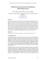
Figure 2: Equipment used for packet sniffing. At the bottom,
from left to right are the ATEQ VT55 TPMS trigger tool, two
tire pressure sensors (TPS-A and TPS-B), and a low noise am-
plifier (LNA). At the top is one laptop connected with a USRP
with a TVRX daughterboard attached.
methodologies to properly decode or spoof sensor mes-
sages. Apart from access to an insider or the actual spec-
ifications, this information requires reverse-engineering
by an adversary. To convey the level of difficulty of this
process for in-car sensor protocols, we provide a brief
walk-through of our approach below, where we begin by
presenting relevant hardware.
Tire pressure sensor equipment. We selected two
representative tire pressure sensors that employ different
modulation schemes. Both sensors are used in automo-
biles with high market shares in the US. To prevent mis-
use of the information here, we refer to these sensors
simply as tire pressure sensor A (TPS-A) and tire pres-
sure sensor B (TPS-B). To help our process, we also ac-
quired a TPMS trigger tool, which is available for a few
hundred dollars. Such tools are handheld devices that
can activate and decode information from a variety of
tire sensor implementations. These tools are commonly
used by car technicians and mechanics for troubleshoot-
ing. For our experiments, we used a TPMS trigger tool
from ATEQ [8] (ATEQ VT55).
Raw signal sniffer. Reverse engineering the TPMS
protocols requires the capture and analysis of raw sig-
nal data. For this, we used GNU Radio [2] in con-
junction with the Universal Software Radio Peripheral
(USRP) [1]. GNU Radio is an open source, free software
toolkit that provides a library of signal processing blocks
that run on a host processing platform. Algorithms im-
plemented using GNU Radio can receive data directly
from the USRP, which is the hardware that provides RF
access via an assortment of daughterboards. They in-
clude the TVRX daughterboard capable of receiving RF
in the range of 50 Mhz to 870 MHz and the LFRX daugh-
terboard able to receive from DC to 30 MHz. For con-
venience, we initially used an Agilent 89600 Vector Sig-
nal Analyzer (VSA) for data capture (but such equipment
is not necessary). The pressure sensor modules, trigger
tool, and software radio platform are shown in Figure 2.
3.1 Reverse Engineering Walk Through
While our public domain search resulted in only high-
level knowledge about the TPM communication proto-
col specifics, anticipating sensor activity in the 315/433
MHz bands did provide us with a starting point for our
reverse engineering analysis.
We began by collecting a few transmissions from each
of the TPM sensors. The VSA was used to narrow down
the spectral bandwidth necessary for fully capturing the
transmissions. The sensors were placed close to the VSA
receiving antenna while we used the ATEQ VT55 to trig-
ger the sensors. Although initial data collections were
obtained using the VSA, the research team switched to
using the USRP to illustrate that our findings (and subse-
quently our attacks) can be achieved with low-cost hard-
ware. An added benefit of using the USRP for the data
collections is that it is capable of providing synchronized
collects for the LF and HF frequency bands — thus al-
lowing us to extract important timing information be-
tween the activation signals and the sensor responses. To
perform these collects, the TVRX and LFRX daughter-
boards were used to provide access to the proper radio
frequencies. Once the sensor bursts were collected, we
began our signal analysis in MATLAB to understand the
modulation and encoding schemes. The final step was to
map out the message format.
Determine coarse physical layer characteristics.
The first phase of characterizing the sensors involved
measuring burst widths, bandwidth, and other physical
layer properties. We observed that burst widths were
on the order of 15 ms. During this initial analysis, we
noted that each sensor transmitted multiple bursts in re-
sponse to their respective activation signals. TPS-A used
4 bursts, while TPS-B responded with 5 bursts. Indi-
vidual bursts in the series were determined to be exact
copies of each other, thus each burst encapsulates a com-
plete sensor report.
Identify the modulation scheme. Analysis of the
baseband waveforms revealed two distinct modulation
schemes. TPS-A employed amplitude shift keying
(ASK), while TPS-B employed a hybrid modulation
scheme — simultaneous usage of ASK and frequency
shift keying (FSK). We speculate that the hybrid scheme
is used for two reasons: (1) to maximize operability with
TPM readers and (2) to mitigate the effects of an adverse
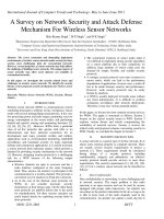
channel during normal operation. Figure 3 illustrates the
differences between the sensors’ transmission in both the
time and frequency domains. The modulation schemes
are also observable in these plots.
5
−100 −50 0 50 100
−80
−60
−40
−20
0
Frequency (KHz)
Magnitude (dB)
TPS−A
−100 −50 0 50 100
−80
−60
−40
−20
0
Frequency (KHz)
TPS−B
2000 2100 2200 2300 2400
−1
−0.5
0
0.5
1
Sample Number
Normalized Magnitude
2000 2100 2200 2300 2400
−1
−0.5
0
0.5
1
Sample Number
Figure 3: A comparison of FFT and signal strength time series
between TSP-A and TSP-B sensors.
Resolve the encoding scheme. Despite the different
modulation schemes, it was immediately apparent that
both sensors were utilizing Manchester encoding (after
distinct preamble sequences). The baud rate is directly
observable under Manchester encoding and was on the
order of 5 kBd. The next step was to determine the bit
mappings from the Manchester encoded signal. In order
to accomplish this goal, we leveraged knowledge of a
known bit sequence in each message. We knew the sen-
sor ID because it was printed on each sensor and assumed
that this bit sequence must be contained in the message.
We found that applying differential Manchester decoding
generated a bit sequence containing the sensor ID.
Reconstructing the message format. While both
sensors used differential Manchester encoding, their
packet formats differed significantly. Thus, our next step
was to determine the message mappings for the rest of
the bits for each sensor. To understand the size and mean-
ing of each bitfield, we manipulated sensor transmissions
by varying a single parameter and observed which bits
changed in the message. For instance, we adjusted the
temperature using hot guns and refrigerators, or adjusted
the pressure. By simultaneously using the ATEQ VT55,
we were also able to observe the actual transmitted val-
ues and correlate them with our decoded bits. Using this
approach, we managed to determine the majority of mes-
sage fields and their meanings for both TPS-A and TPS-
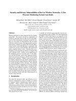
B. These included temperature, pressure, and sensor ID,
as illustrated in Figure 4. We also identified the use of
a CRC checksum and determined the CRC polynomials
through a brute force search.
At this point, we did not yet understand the meaning
of a few bits in the message. We were later able to recon-
struct these by generating messages with our software ra-
dio, changing these bits, and observing the output of the
preamble Sensor ID Pressure Temperature Flags Checksum
Figure 4: An illustration of a packet format. Note the size is
not proportional to real packet fields.
TPMS tool or a real car. It turned out that these were pa-
rameters like battery status, over which we had no direct
control by purely manipulating the sensor module. More
details on message spoofing are presented in Section 5.
3.2 Lessons Learned
The aforementioned reverse-engineering can be accom-
plished with a reasonable background in communica-
tions and computer engineering. It took a few days for
a PhD-level engineer experienced with reverse engineer-
ing to build an initial system. It took several weeks for an
MS-level student with no prior experience in reverse en-
gineering and GNU Radio programming to understand
and reproduce the attack. The equipment used (the
VTEQ VT55 and USRP attached with TVRX) is openly
available and costs $1500 at current market prices.
Perhaps one of the most difficult issues involved baud
rate estimation. Since Manchester encoding is used, our
initial baud rate estimates involved averaging the gaps
between the transition edges of the signal. However, the
jitter (most likely associated with the local oscillators of
the sensors) makes it almost impossible to estimate a
baud rate accurate enough for a simple software-based
decoder to work correctly. To address this problem, we
modified our decoders to be self-adjustable to compen-
sate for the estimation errors throughout the burst.
The reverse engineering revealed the following obser-
vations. First, it is evident that encryption has not been
used—which makes the system vulnerable to various at-
tacks. Second, each message contains a 28-bit or 32-bit
sensor ID depending on the type of sensor. Regardless
of the sensor type, the IDs do not change during the sen-
sors’ lifetimes.
Given that there are 254.4 million registered passenger
vehicles in United States [34], one 28-bit Sensor ID is
enough to track each registered car. Even in the future
when the number of cars may exceed 256 million, we
can still identify a car using a collection of tire IDs —
a 4-tuple of tire IDs. Assuming a uniform distribution
across the 28-bit ID space, the probability of an exact
match of two cars’ IDs is 4!/2
112
without considering
the ordering. To determine how many cars R can be on
the road in the US with a guarantee that there is a less
than P chance of any two or more cars having the same
ID-set, is a classical birthday problem calculation:
R =
2
113
4!
ln(
1
1 − P
)
6
usrp_rx_cfile.py
pipe
GnuRadio
Packet
Detector
Demod
classifier
FSK Decoder
ASK Decoder
Temperature:xx
pressure: xx
Sensor ID: xx
Temperature:xx
pressure: xx
Sensor ID: xx
Figure 5: Block chart of the live decoder/eavesdropper.
To achieve a match rate of larger than P = 1%, more
than 10
15
cars need to be on the road, which is signif-
icantly more than 1 billion cars. This calculation, of
course, is predicated on the assumption of a uniform al-
location across the 28-bit ID space. Even if we relax this
assumption and assume 20 bits of entropy in a single 28-
bit ID space, we would still need roughly 38 billion cars
in the US to get a match rate of more than P = 1%.
We note that this calculation is based on the unrealis-
tic assumption that all 38 billion cars are co-located, and
are using the same modulation and coding schemes. Ul-
timately, it is very unlikely to have two cars that would
be falsely mistaken for each other.
4 Feasibility of Eavesdropping
A critical question for evaluating privacy implications of
in-car wireless networks is whether the transmissions can
be easily overheard from outside the vehicle body. While
tire pressure data does not require strong confidentiality,
the TPMS protocols contain identifiers that can be used
to track the locations of a device. In practice, the proba-
bility that a transmission can be observed by a stationary
receiver depends not only on the communication range
but also on the messaging frequency and speed of the
vehicle under observation, because these factors affect
whether a transmission occurs in communication range.
The transmission power of pressure sensors is rela-
tively small to prolong sensor battery lifetime and reduce
cross-interference. Additionally, the NHTSA requires
tire pressure sensors to transmit data only once every 60
seconds to 90 seconds. The low transmission power, low
data report rate, and high travel speeds of automobiles
raise questions about the feasibility of eavesdropping.
In this section, we experimentally evaluate the range
of TPMS communications and further evaluate the feasi-
bility of tracking. This range study will use TPS-A sen-
sors, since their TPMS uses a four-antenna structure and
operates at a lower transmission power. It should there-
fore be more difficult to overhear.
4.1 Eavesdropping System
During the reverse engineering steps, we developed
two Matlab decoders: one for decoding ASK mod-
ulated TPS-A and the other for decoding the FSK
modulated TPS-B. In order to reuse our decoders yet
be able to constantly monitor the channel and only
record useful data using GNU radio together with the
USRP, we created a live decoder/eavesdropper leverag-
ing pipes. We used the GNU Radio standard Python
script usrp rx cfile.py to sample channels at a rate
of 250 kHz, where the recorded data was then piped to a
packet detector. Once the packet detector identifies high
energy in the channel, it extracts the complete packet and
passes the corresponding data to the decoder to extract
the pressure, temperature, and the sensor ID. If decoding
is successful, the sensor ID will be output to the screen
and the raw packet signal along with the time stamp will
be stored for later analysis. To be able to capture data
from multiple different TPMS systems, the eavesdrop-
ping system would also need a modulation classifier to
recognizes the modulation scheme and choose the corre-
sponding decoder. For example, Liedtke’s [29] algorithm
could be used to differentiate ASK2 and FSK2. Such an
eavesdropping system is depicted in Fig. 5.
In early experiments, we observed that the decoding
script generates much erratic data from interference and
artifacts of the dynamic channel environment. To address
this problem, we made the script more robust and added
a filter to discard erroneous data. This filter drops all
signals that do not match TPS-A or TPS-B. We have
tested our live decoder on the interstate highway I-26
(Columbia, South Carolina) with two cars running in par-
allel at speeds exceeding 110 km/h.
4.2 Eavesdropping Range
We measured the eavesdropping range in both indoor and
outdoor scenarios by having the ATEQ VT55 trigger the
sensors. In both scenarios, we fixed the location of the
USRP at the origin (0, 0) in Figure 7 and moved the
sensor along the y-axis. In the indoor environment, we
studied the reception range of stand-alone sensors in a
hallway. In the outdoor environment, we drove one of
the authors’ cars around to measure the reception range
of the sensors mounted in its front left wheel while the
car’s body was parallel to the x-axis, as shown in Fig-
ure 7. In our experiment, we noticed that we were able
to decode the packets when the received signal strength is
larger than the ambient noise floor. The resulting signal
strength over the area where packets could be decoded
7
Eavesdropping
range
Indoor
noise floor
Outdoor
noise floor
Boosted
range
Amplified
noise floor
Original
noise floor
Original
range
(a) indoor vs. outdoor (w/o LNA) (b) with LNA vs. without LNA (indoor)
Figure 6: Comparison of eavesdropping range of TPS-A.
successfully and the ambient noise floors are depicted
in Figure 6 (a). The results show that both the outdoor
and indoor eavesdropping ranges are roughly 10.7 m, the
vehicle body appears only to have a minor attenuation
effect with regard to a receiver positioned broadside.
We next performed the same set of range experiments
while installing a low noise amplifier (LNA) between the
antenna and the USRP radio front end, as shown in Fig-
ure 2. As indicated in Figure 6, the signal strength of
the sensor transmissions still decreased with distance and
the noise floor was raised because of the LNA, but the
LNA amplified the received signal strength and improved
the decoding range from 10.7 meters to 40 meters. This
shows that with some inexpensive hardware a significant
eavesdropping range can be achieved, a range that allows
signals to be easily observed from the roadside.
Note that other ways to boost receiving range exist.
Examples include the use of directional antennas or more
sensitive omnidirectional antennas. We refer readers to
the antenna studies in [9, 15, 42] for further information.
4.3 Eavesdropping Angle Study
We now investigate whether the car body has a larger
attenuation effect if the receiver is located at different
angular positions. We also study whether one USRP is
enough to sniff packets from all four tire sensors.
The effect of car body. In our first set of experiments,
we studied the effect of the car’s metallic body on signal
attenuation to determine the number of required USRPs.
We placed the USRP antenna at the origin of the coordi-
nate, as shown in Figure 7, and position the car at several
points on the line of y = 0.5 with its body parallel to
the x-axis. Eavesdropping at these points revealed that it
is very hard to receive packets from four tires simultane-
ously. A set of received signal strength (RSS) measure-
ments when the front left wheel was located at (0, 0.5)
meters are summarized in Table 1. Results show that
the USRP can receive packets transmitted by the front
left, front right and rear left sensors, but not from the
rear right sensor due to the signal degradation caused by
the car’s metallic body. Thus, to assure receiving pack-
ets from all four sensors, at least two observation spots
may be required, with each located on either side of the
car. For instance, two USRPs can be placed at different
spots, or two antennas connected to the same USRP can
be meters apart.
The eavesdropping angle at various distances. We
studied the range associated with one USRP receiving
packets transmitted by the front left wheel. Again, we
placed the USRP antenna at the origin and recorded
packets when the car moved along trajectories parallel to
the x-axis, as shown in Figure 7. These trajectories were
1.5 meters apart. Along each trajectory, we recorded
RSS at the locations from where the USRP could decode
packets. The colored region in Figure 11, therefore, de-
notes the eavesdropping range, and the contours illustrate
the RSS distribution of the received packets.
From Figure 11, we observe that the maximum hori-
zontal eavesdropping range, r
max
, changes as a function
of the distance between the trajectory and the USRP an-
tenna, d. Additionally, the eavesdropping ranges on both
sides of the USRP antenna are asymmetric due to the
car’s metallic body. Without the reflection and imped-
iment of the car body, the USRP is able to receive the
packets at further distances when the car is approaching
rather than leaving. The numerical results of r
max
, ϕ
1
,
the maximum eavesdropping angle when the car is ap-
proaching the USRP, and ϕ
2
, the maximum angle when
the car is leaving the USRP, are listed in Figure 8. Since
Location RSS (dB) Location RSS (dB)
Front left -41.8 Rear left -55.0
Front right -54.4 Rear right N/A
Table 1: RSS when USPR is located 0.5 meters away from the
front left wheel.
8
Y
X
φ
1
φ
2
r
max
d
0
Figure 7: The experiment setup for the range study.
the widest range of 9.1 meters at the parallel trajectory
was 3 meters away from the x-axis, an USRP should be
placed 2.5 meters away from the lane marks to maximize
the chance of packet reception, assuming cars travel 0.5
meter away from lane marks.
Messaging rate. According to NHTSA regulations,
TPMS sensors transmit pressure information every 60
to 90 seconds. Our measurements confirmed that both
TPS-A and TPS-B sensors transmit one packet every 60
seconds or so. Interestingly, contrary to documentation
(where sensors should report data periodically after a
speed higher than 40 km/h), both sensors periodically
transmit packet even when cars are stationary. Further-
more, TPS-B transmits periodic packets even when the
car is not running.
4.4 Lessons Learned: Feasibility of Track-
ing Automobiles
The surprising range of 40m makes it possible to capture
a packet and its identifiers from the roadside, if the car
is stationary (e.g., a traffic light or a parking lot). Given
that a TPMS sensor only send one message per minute,
tracking becomes difficult at higher speeds. Consider, for
example, a passive tracking system deployed along the
roadside at highway entry and exit ramps, which seeks
to extract the unique sensor ID for each car and link en-
try and exit locations as well as subsequent trips. To en-
sure capturing at least one packet, a row of sniffers would
be required to cover the stretch of road that takes a car
60 seconds to travel. The number of required sniffers,
n
passive
= ceil(v ∗ T /r
max
), where v is the speed of
the vehicle, T is the message report period, and r
max
is
the detection range of the sniffer. Using the sniffing sys-
tem described in previous sections where r
max
= 9.1
m, 110 sniffers are required to guarantee capturing one
packet transmitted by a car traveling at 60 km/h. De-
ploying such a tracking system appears cost-prohibitive.
It is possible to track with fewer sniffers, however, by
leveraging the activation signal. The tracking station can
send the 125kHz activation signal to trigger a transmis-
sion by the sensor. To achieve this, the triggers and snif-
x (meters) (dB)
y (meters)
−3 −2 −1 0 1 2 3 4 5
2
3
4
5
6
7
−56
−55
−54
−53
−52
−51
−50
−49
−48
−47
Figure 11: Study the angle of eavesdropping with LNA.
fers should be deployed in a way such that they meet
the following requirements regardless of the cars’ travel
speeds: (1) the transmission range of the trigger should
be large enough so that the passing car is able to receive
the complete activation signal; (2) the sniffer should be
placed at a distance from the activation sender so that the
car is in the sniffers’ eavesdropping range when it starts
to transmit; and (3) the car should stay within the eaves-
dropping range before it finishes the transmission.
To determine the configuration of the sniffers and the
triggers, we conducted an epitomical study using a USRP
with two daughterboards attached, one recording at 125
kHz and the other recording at 315 MHz. Our results
are depicted in Figure 9 and show that the activation sig-
nal of TPS-B lasts approximately 359 ms. The sensors
start to transmit 530 ms after the beginning of the acti-
vation signal, and the data takes 15 ms to transmit. This
means, that to trigger a car traveling at 60 km/h, the trig-
ger should have a transmission range of at least 6 meters.
Since a sniffer can eavesdrop up to 9.1 meters, it suffices
to place the sniffer right next to the trigger. Additional
sniffers could be placed down the road to capture pack-
ets of cars traveling at higher speeds.
To determine the feasibility of this approach, we have
conducted a roadside experiment using the ATEQ VT55
which has a transmission range of 0.5 meters. We were
able to activate and extract the ID of a targeted TPMS
sensor moving at the speed of 35 km/h using one sniffer.
We note that ATEQ VT55 was deliberately designed with
short transmission range to avoid activating multiple cars
in the dealership. With a different radio frontend, such as
using a matching antenna for 125 kHz, one can increase
the transmission range of the trigger easily and enable
capturing packets from cars at higher speeds.
Comparison between tracking via TPMS and Au-
tomatic Number Plate Reading. Automatic Number
Plate Reading (ANPR) technologies have been proposed
to track automobiles and leverage License Plate Cap-
ture Cameras (LPCC) to recognize license plate num-
bers. Due to the difference between underlying technolo-
9
d (m) ϕ
1
(
◦
) ϕ
2
(
◦
) r
max
(m)
1.5 72.8 66.8 8.5
3.0 59.1 52.4 9.1
4.5 45.3 31.8 7.5
6.0 33.1 20.7 6.3
7.5 19.6 7.7 3.8
Figure 8: The eavesdropping angles and
ranges when the car is traveling at various
trajectories.
0 0.2 0.4 0.6 0.8 1 1.2 1.4
0
0.5
1
Time (seconds)
Normalized Magnitude
Activation
Data
Figure 9: Time series of activation and
data signals.
Figure 10: Frequency mixer and USRP
with two daughterboards are used to
transmit data packets at 315/433 MHz.
gies, TPMS and ANPR systems exhibit different charac-
teristics. First, ANPR allows for more direct linkage to
individuals through law enforcement databases. ANPR
requires, however, line of sight (LOS) and its accuracy
can be affected by weather conditions (e.g. light or hu-
midity) or the dirt on the plate. In an ideal condition with
excellent modern systems, the read rate for license plates
is approximately 90% [25]. A good quality ANPR cam-
era can recognize number plates at 10 meters [5]. On
the contrary, the ability to eavesdrop on the RF transmis-
sion of TPMS packets does not depend on illumination
or LOS. The probability of identifying the sensor ID is
around 99% when the eavesdropper is placed 2.5 meters
away from the lane marks. Second, the LOS require-
ment forces the ANPR to be installed in visible locations.
Thus, a motivated driver can take alternative routes or re-
move/cover the license plates to avoid being detected. In
comparison, the use of TPMS is harder to circumvent,
and the ability to eavesdrop without LOS could lead to
more pervasive automobile tracking. Although swapping
or hiding license plates requires less technical sophistica-
tion, it also imposes much higher legal risks than deacti-
vating TPMS units.
5 Feasibility of Packet Spoofing
Being able to eavesdrop on TPMS communication from
a distance allows us to further explore the feasibility of
inserting forged data into safety-critical in-vehicle sys-
tems. Such a threat presents potentially even greater
risks than the tracking risks discussed so far. While
the TPMS is not yet a highly safety-critical system, we
experimented with spoofing attacks to understand: (1)
whether the receiver sensitivity of an in-car radio is high
enough to allow spoofing from outside the vehicle or a
neighboring vehicle, and (2) security mechanisms and
practices in such systems. In particular, we were curious
whether the system uses authentication, input validation,
or filtering mechanisms to reject suspicious packets.
The packet spoofing system. Our live eavesdrop-
per can detect TPMS transmission and decode both ASK
modulated TPS-A messages and FSK modulated TPS-
B messages in real time. Our packet spoofing system is
built on top of our live eavesdropper, as shown in Fig-
ure 12. The Packet Generator takes two sets of parame-
ters —sensor type and sensor ID from the eavesdropper;
temperature, pressure, and status flags from users—and
generates a properly formulated message. It then modu-
lates the message at baseband (using ASK or FSK) while
inserting the proper preamble. Finally, the rogue sensor
packets are upconverted and transmitted (either contin-
uously or just once) at the desired frequency (315/433
MHz) using a customized GNU radio python script. We
note that once the sensor ID and sensor type are captured
we can create and repeatedly transmit the forged message
at a pre-defined period.
At the time of our experimentation, there were no
USRP daughterboards available that were capable of
transmitting at 315/433 MHz. So, we used a frequency
mixing approach where we leveraged two XCVR2450
daughterboards and a frequency mixer (mini-circuits
ZLW11H) as depicted in Fig.10. By transmitting a tone
out of one XCVR2450 into the LO port of the mixer,
we were able to mix down the spoofed packet from the
other XCVR2450 to the appropriate frequency. For 315
MHz, we used a tone at 5.0 GHz and the spoofed packet
at 5.315 GHz.
1
To validate our system, we decoded spoofed packets
with the TPMS trigger tool. Figure 13 shows a screen
snapshot of the ATEQ VT55 after receiving a spoofed
packet with a sensor ID of “DEADBEEF” and a tire pres-
sure of 0 PSI. This testing also allowed us to understand
the meaning of remaining status flags in the protocol.
5.1 Exploring Vehicle Security
We next used this setup to send various forged packets
to a car using TPS-A sensors (belonging to one of the
1
For 433 MHz, the spoofed packet was transmitted at 5.433 GHz.
We have also successfully conducted the experiment using two RFX-
1800 daughterboards, whose operational frequencies are from 1.5 GHz
to 2.1 GHz.
10
Eavesdropper
Packet
Generator
Sensor
ID
Sensor
Type
USRP Tx
GnuRadio
Figure 12: Block chart of the packet spoofing system.
authors) at a rate of 40 packets per second. We made the
following observations.
No authentication. The vehicle ECU ignores packets
with a sensor ID that does not match one of the known
IDs of its tires, but appears to accept all other packets.
For example, we transmitted forged packets with the ID
of the left front tire and a pressure of 0 PSI and found 0
PSI immediately reflected on the dashboard tire pressure
display. By transmitting messages with the alert bit set
we were able to immediately illuminate the low-pressure
warning light
2
, and with about 2 seconds delay the ve-
hicle’s general-information warning light, as shown in
Figure 14.
No input validation and weak filtering. We forged
packets at a rate of 40 packets per second. Neither this
increased rate, nor the occasional different reports by
the real tire pressure sensor seemed to raise any suspi-
cion in the ECU or any alert that something was wrong.
The dashboard simply displayed the spoofed tire pres-
sure. We next transmitted two packets with very differ-
ent pressure values alternately at a rate of 40 packets per
second. The dashboard display appeared to randomly
alternate between these values. Similarly, when alter-
nating between packets with and without the alert flag,
we observed the warning lights switched on and off at
non-deterministic time intervals. Occasionally, the dis-
play seemed to freeze on one value. These observations
suggest that TPMS ECU employs trivial filtering mecha-
nisms which can be easily confused by spoofed packets.
Interestingly, the illumination of the low-pressure
warning light depends only on the alert bit—the light
turns on even if the rest of the message reports a nor-
mal tire pressure of 32 PSI! This further illustrates that
the ECU does not appear to use any input validation.
Large range of attacks. We first investigated the
effectiveness of packet spoofing when vehicles are sta-
tionary. We measured the attack range when the packet
spoofing system was angled towards the head of the car,
and we observed a packet spoofing range of 38 meters.
For the purpose of proving the concept, we only used
low-cost antennas and radio devices in our experiments.
We believe that the range of packet spoofing can be
greatly expanded by applying amplifiers, high-gain an-
tennas, or antenna arrays.
2
To discover this bit we had to deflate one tire and observe the tire
pressure sensors response. Simply setting a low pressure bit or report-
ing low pressure values did not trigger any alert in the vehicle.
Feasibility of Inter-Vehicle Spoofing. We deployed
the attacks against willing participants on highway I-26
to determine if they are viable at high speeds. Two cars
owned by the authors were involved in the experiment.
The victim car had TPS-A sensors installed and the at-
tacker’s car was equipped with our packet spoofing sys-
tem. Throughout our experiment, we transmitted alert
packets using the front-left-tire ID of the target car, while
the victim car was traveling to the right of the attacker’s
car. We observed that the attacker was able to trigger
both the low-pressure warning light and the car’s central-
warning light on the victim’s car when traveling at 55
km/h and 110 km/h, respectively. Additionally, the low-
pressure-warning light illuminated immediately after the
attacker entered the packet spoofing range.
5.2 Exploring the Logic of ECU Filtering
Forging a TPMS packet and transmitting it at a high rate
of 40 packets per second was useful to validate packet
spoofing attacks and to gauge the spoofing range. Be-
yond this, though, it was unclear whether there were fur-
ther vulnerabilities in the ECU logic. To characterize the
logic of the ECU filtering mechanisms, we designed a
variety of spoofing attacks. The key questions to be an-
swered include: (1) what is the minimum requirement to
trigger the TPMS warning light once, (2) what is the min-
imum requirement to keep the TPMS warning light on
for an extended amount of time, and (3) can we perma-
nently illuminate any warning light even after stopping
the spoofing attack?
So far, we have observed two levels of warning lights:
TPMS Low-Pressure Warning light (TPMS-LPW) and
the vehicle’s general-information warning light illustrat-
ing ‘Check Tire Pressure’. In this section, we explored
the logic of filtering strategies related to the TPMS-
LPW light in detail. The logic controlling the vehicle’s
general-information warning light can be explored in a
similar manner.
5.2.1 Triggering the TPMS-LPW Light
To understand the minimum requirement of triggering
the TPMS-LPW light, we started with transmitting one
spoofed packet with the rear-left-tire ID and eavesdrop-
ping the entire transmission. We observed that (1) one
spoofed packet was not sufficient to trigger the TPMS-
LPW light; and (2) as a response to this packet, the
TPMS ECU immediately sent two activation signals
through the antenna mounted close to the rear left tire,
causing the rear left sensor to transmit eight packets.
Hence, although a single spoofed packet does not cause
the ECU to display any warning, it does open a vulnera-
bility to battery drain attacks.
11
Figure 13: The TPMS trigger tool dis-
plays the spoofed packet with the sen-
sor ID “DEADBEEF”. We crossed out
the brand of TP sensors to avoid legal
issues.
(a) (b)
Figure 14: Dash panel snapshots: (a) the tire pressure of left front tire displayed
as 0 PSI and the low tire pressure warning light was illuminated immediately after
sending spoofed alert packets with 0 PSI; (b) the car computer turned on the general
warning light around 2 seconds after keeping sending spoofed packets.
Next, we gradually increased the number of spoofed
packets, and we found that transmitting four spoofed
packets in one second suffices to illuminate the TPMS-
LPW light. Additionally, we found that those four
spoofed packets have to be at least 225 ms apart, oth-
erwise multiple spoofed packets will be counted as one.
When the interval between two consecutive spoofed
packets is larger than 4 seconds or so, the TPMS-LPW
no longer illuminates. This indicates that TPMS adopts
two detection windows with sizes of 240 ms (a packet
lasts for 15 ms) and 4 seconds. A 240-ms window is
considered positive for low tire pressure if at least one
low-pressure packet has been received in that window
regardless of the presence of numerous normal packets.
Four 240-ms windows need to be positive to illuminate
the TPMS-LPW light. However, the counter for positive
240-ms windows will be reset if no low-pressure packet
is received within a 4-s window.
Although the TPMS ECU does use a counting thresh-
old and window-based detection strategies, they are de-
signed to cope with occasionally corrupted packets in a
benign situation and are unable to deal with malicious
spoofing. Surprisingly, although the TPMS ECU does
receive eight normal packets transmitted by sensors as
a response to its queries, it still concludes the low-tire-
pressure status based on one forged packet, ignoring the
majority of normal packets!
5.2.2 Repeatedly Triggering the TPMS-LPW Light
The TPMS-LPW light turns off a few seconds if only
four forged packets are received. To understand how
to sustain the warning light, we repeatedly transmitted
spoofed packets and increased the spoofing period grad-
ually. The TPMS-LPW light remained illuminated when
we transmitted the low-pressure packet at a rate higher
than one packet per 240 ms, e.g., one packet per detection
window. Spoofing at a rate between one packet per 240
ms to 4 seconds caused the TPMS-LPW light to toggle
between on and off. However, spoofing at a rate slower
than 4 seconds could not activate the TPMS-LPW light,
which confirmed our prior experiment results. Figure 15
depicts the measured TPMS-LPW light on-durations and
off-durations when the spoofing periods increased from
44 ms to 4 seconds.
As we increased the spoofing period, the TPMS-LPW
light remained on for about 6 seconds on average, but
the TPMS-LPW light stayed off for an incrementing
amount of time which was proportional to the spoofing
period. Therefore, it is very likely that the TPMS-ECU
adopts a timer to control the minimum on-duration and
the off-duration of TPMS-LPW light can be modeled as
t
of f
= 3.5x + 4, where x is the spoofing period. The
off-duration includes the amount of time to observe four
low-pressure forged messages plus the minimum waiting
duration for the TPMS-ECU to remain off, e.g., 4 sec-
onds. In fact, this confirms our observation that there is
a waiting period of approximately 4 seconds before the
TPMS warning light was first illuminated.
5.2.3 Beyond Triggering the TPMS-LPW Light
Our previous spoofing attacks demonstrated that we can
produce false TPMS-LPW warnings. In fact, transmit-
ting forged packets at a rate higher than one packet per
second also triggered the vehicle’s general-information
warning light illustrating ‘Check Tire Pressure’. De-
pending on the spoofing period, the gap between the
illumination of the TPMS-LPW light and the vehicle’s
general-information warning light varied between a few
seconds to 130 seconds — and the TPMS-LPW light re-
mained illuminated afterwards.
Throughout our experiments, we typically exposed the
car to spoofed packets for a duration of several minutes at
a time. While the TPMS-LPW light usually disappeared
about 6 seconds after stopping spoofed message trans-
missions, we were once unable to reset the light even by
turning off and restarting the ignition. It did, however,
reset after about 10 minutes of driving.
To our surprise, at the end of only two days of spo-
radic experiments involving triggering the TPMS warn-
ing on and off, we managed to crash the TPMS ECU and
12
0 1 2 3 4
0
5
10
15
20
25
Spoofing period (s)
Duration of dashboard display (s)
Warning On
Warning Off
Figure 15: TPMS low-pressure warning light on and off dura-
tion vs. spoofing periods.
completely disabled the service. The vehicle’s general-
information warning light illustrating ‘Check TPMS Sys-
tem’ was activated and no tire pressure information was
displayed on the dashboard, as shown in Figure 16. We
attempted to reset the system by sending good packets,
restarting the car, driving on the highway for hours, and
unplugging the car battery. None of these endeavors
were successful. Eventually, a visit to a dealership recov-
ered the system at the cost of replacing the TPMS ECU.
This incident suggests that it may be feasible to crash the
entire TPMS and the degree of such an attack can be so
severe that the owner has no option but to seek the ser-
vices of a dealership. We note that one can easily explore
the logic of a vehicle’s general-information warning light
using similar methods for TPMS-LPW light. We did not
pursue further analysis due to the prohibitive cost of re-
pairing the TPMS ECU.
5.3 Lessons Learned
The successful implementation of a series of spoofing at-
tacks revealed that the ECU relies on sensor IDs to filter
packets, and the implemented filter mechanisms are not
effective in rejecting packets with conflicting informa-
tion or abnormal packets transmitted at extremely high
rates. In fact, the current filer mechanisms introduce se-
curity risks. For instance, the TPMS ECU will trigger
the sensors to transmit several packets after receiving one
spoofed message. Those packets, however, are not lever-
aged to detect conflicts and instead can be exploited to
launch battery drain attacks. In summary, the absence of
authentication mechanisms and weak filter mechanisms
open many loopholes for adversaries to explore for more
‘creative’ attacks. Furthermore, despite the unavailabil-
ity of a radio frontend that can transmit at 315/433 MHz,
we managed to launch the spoofing attack using a fre-
quency mixer. This result is both encouraging and alarm-
ing since it shows that an adversary can spoof packets
even without easy access to transceivers that operate at
the target frequency band.
(a) (b)
Figure 16: Dash panel snapshots indicating the TPMS system
error (this error cannot be reset without the help of a dealer-
ship): (a) the vehicle’s general-information warning light; (b)
tire pressure readings are no longer displayed as a result of sys-
tem function errors.
6 Protecting TPMS Systems from Attacks
There are several steps that can improve the TPMS de-
pendability and security. Some of the problems arise
from poor system design, while other issues are tied to
the lack of cryptographic mechanisms.
6.1 Reliable Software Design
The first recommendation that we make is that software
running on TPMS should follow basic reliable software
design practices. In particular, we have observed that it
was possible to convince the TPMS control unit to dis-
play readings that were clearly impossible. For example,
the TPMS packet format includes a field for tire pressure
as well as a separate field for warning flags related to tire
pressure. Unfortunately, the relationship between these
fields were not checked by the TPMS ECU when pro-
cessing communications from the sensors. As noted ear-
lier, we were able to send a packet containing a legitimate
tire pressure value while also containing a low tire pres-
sure warning flag. The result was that the driver’s dis-
play indicated that the tire had low pressure even though
its pressure was normal. A straight forward fix for this
problem (and other similar problems) would be to update
the software on the TPMS control unit to perform con-
sistency checks between the values in the data fields and
the warning flags. Similarly, when launching message
spoofing attacks, although the control unit does query
sensors to confirm the low pressure, it neglects the le-
gitimate packet responses completely. The control unit
could have employed some detection mechanism to, at
least, raise an alarm when detecting frequent conflicting
information, or have enforced some majority logic oper-
ations to filter out suspicious transmissions.
6.2 Improving Data Packet Format
One fundamental reason that eavesdropping and spoof-
ing attacks are feasible in TPMS systems is that packets
are transmitted in plaintext. To prevent these attacks, a
13
first line of defense is to encrypt TPM packets
3
. The ba-
sic packet format in a TPMS system included a sensor ID
field, fields for temperature and tire pressure, fields for
various warning flags, and a checksum. Unfortunately,
the current packet format used is ill-suited for proper en-
cryption, since naively encrypting the current packet for-
mat would still support dictionary-based cryptanalysis as
well as replay attacks against the system. For this reason,
we recommend that an additional sequence number field
be added to the packet to ensure freshness of a packet.
Further, requiring that the sequence number field be in-
cremented during each transmission would ensure that
subsequent encrypted packets from the same source be-
come indistinguishable, thereby making eavesdropping
and cryptanalysis significantly harder. We also recom-
mend that an additional cryptographic checksum (e.g. a
message authentication code) be placed prior to the CRC
checksum to prevent message forgery.
Such a change in the payload would require that
TPMS sensors have a small amount memory in order to
store cryptographic keys, as well as the ability to perform
encryption. An obvious concern is the selection of cryp-
tographic algorithms that are sufficiently light-weight to
be implemented on the simple processor within a TPMS
sensor, yet also resistant to cryptanalysis. A secondary
concern is the installation of cryptographic keys. We en-
vision that the sensors within a tire would be have keys
pre-installed, and that the corresponding keys could be
entered into the ECU at the factory, dealership, or a cer-
tified garage. Although it is unlikely that encryption and
authentication keys would need to be changed, it would
be a simple matter to piggy-back a rekeying command
on the 125kHz activation signal in a manner that only
certified entities could update keys.
6.3 Preventing Spoofed Activation
The spoofing of an activation signal forces sensors to
emit packets and facilitates tracking and battery drain at-
tacks. Although activation signals are very simple, they
can convey a minimal amount of bits. Thus, using a long
packet format with encryption and authentication is un-
suitable, and instead we suggest that the few bits they can
convey be used as a sequencing field, where the sequenc-
ing follows a one-way function chain in a manner anal-
ogous to one-time signatures. Thus, the ECU would be
responsible for maintaining the one-way function chain,
and the TPMS sensor would simply hash the observed
sequence number and compare with the previous se-
quence number. This would provide a simple means of
filtering out false activation signals. We note that other
3
We note that encrypting the entire message (or at least all fields
that are not constant across different cars) is essential as otherwise the
ability to read these fields would support a privacy breach.
legitimate sources of activation signals are specialized
entities, such as dealers and garages, and such entities
could access an ECU to acquire the position within the
hash chain in order to reset their activation units appro-
priately to allow them to send valid activation signals.
7 Related Work
Wireless devices have become an inseparable part of our
social fabric. As such, much effort has been dedicated
to analyze the their privacy and security issues. Devices
being studied include RFID systems [27, 30, 41], mass-
market UbiComp devices [38], household robots [14],
and implantable medical devices [21]. Although our
work falls in the same category and complements those
works, TPMS in automobiles exhibits distinctive features
with regard to the radio propagation environment (strong
reflection within and off metal car bodies), ease of access
by adversaries (cars are left unattended in public), span
of usage, a tight linkage to the owners, etc. All these
characteristics have motivated this in-depth study on the
security and privacy of TPMS.
One related area of research is location privacy in
wireless networks, which has attracted much attention
since wireless devices are known to present tracking
risks through explicit identifiers in protocols or identi-
fiable patterns in waveforms. In the area of WLAN,
Brik et al. have shown the possibility to identify users
by monitoring radiometric signatures [10]. Gruteser et
al. [19] demonstrated that one can identify a user’s loca-
tion through link- and application-layer information. A
common countermeasure against breaching location pri-
vacy is to frequently dispose user identity. For instance,
Jiang et al. [24] proposed a pseudonym scheme where
users change MAC addresses each session. Similarly,
Greenstein et al. [18] have suggested an identifier-free
mechanism to protect user identities, whereby users can
change addresses for each packet.
In cellular systems, Lee et al. have shown that the lo-
cation information of roaming users can be released to
third parties [28], and proposed using the temporary mo-
bile subscriber identifier to cope with the location privacy
concern. IPv6 also has privacy concerns caused by the
fixed portion of the address [32], and thus the use of peri-
odically varying pseudo-random addresses has been rec-
ommended. The use of pseudonyms is not sufficient to
prevent automobile tracking since the sensors report tire
pressure and temperature readings, which can be used
to build a signature of the car. Furthermore, pseudonyms
cannot defend against packet spoofing attacks such as we
have examined in this paper.
Security and privacy in wireless sensor networks have
been studied extensively. Perrig et al. [37] have proposed
a suite of security protocols to provide data confidential-
14
ity and authentication for resource-constrained sensors.
Random key predistribution schemes [12] have been pro-
posed to establish pairwise keys between sensors on de-
mand. Those key management schemes cannot work
well with TPMS, since sensor networks are concerned
with establishing keys among a large number of sensors
while the TPMS focuses on establishing keys between
four sensors and the ECU only.
Lastly, we note related work on the security of a car’s
computer system [26]. Their work involved analyzing
the computer security within a car by directly mounting
a malicious component into a car’s internal network via
the On Broad Diagnostics (OBD) port (typically under
the dash board), and differs from our work in that we
were able to remotely affect an automobile’s security at
distances of 40 meters without entering the car at all.
8 Concluding Remarks
Tire Pressure Monitoring Systems (TPMS) are the first
in-car wireless network to be integrated into all new cars
in the US and will soon be deployed in the EU. This pa-
per has evaluated the privacy and security implications
of TPMS by experimentally evaluating two representa-
tive tire pressure monitoring systems. Our study revealed
several security and privacy concerns. First, we reverse
engineered the protocols using the GNU Radio in con-
junction with the Universal Software Radio Peripheral
(USRP) and found that: (i) the TPMS does not employ
any cryptographic mechanisms and (ii) transmits a fixed
sensor ID in each packet, which raises the possibility of
tracking vehicles through these identifiers. Sensor trans-
missions can be triggered from roadside stations through
an activation signal. We further found that neither the
heavy shielding from the metallic car body nor the low-
power transmission has reduced the range of eavesdrop-
ping sufficiently to reduce eavesdropping concerns. In
fact, TPMS packets can be intercepted up to 40 meters
from a passing car using the GNU Radio platform with a
low-cost, low-noise amplifier. We note that the eaves-
dropping range could be further increased with direc-
tional antennas, for example.
We also found out that current implementations do
not appear to follow basic security practices. Messages
are not authenticated and the vehicle ECU also does not
appear to use input validation. We were able to inject
spoofed messages and illuminate the low tire pressure
warning lights on a car traveling at highway speeds from
another nearby car, and managed to disable the TPMS
ECU by leveraging packet spoofing to repeatedly turn on
and off warning lights.
Finally, we have recommended security mechanisms
that can alleviate the security and privacy concerns pre-
sented without unduly complicating the installation of
new tires. The recommendations include standard reli-
able software design practices and basic cryptographic
recommendations. We believe that our analysis and rec-
ommendations on TPMS can provide guidance towards
designing more secure in-car wireless networks.
References
[1] Ettus Research LLC. />[2] GNU radio. .
[3] IEEE 1609: Family of Standards for Wire-
less Access in Vehicular Environments (WAVE).
sheet.asp?f=80.
[4] Portable, solar-powered tag readers could
improve traffic management. Available at
/>[5] RE-BCC7Y Number plate recognition cameras.
lettura targhe.htm.
[6] Traffic hackers hit red light. Available at
/>/08/68507.
[7] Improving the safety and environmental performance of
vehicles. EUROPA-Press Releases (23rd May 2008).
[8] ATEQ VT55. />ateqvt55.php.
[9] BAL A NIS , C., AND IOANNI DES , P. Introduction to smart
antennas. Synthesis Lectures on Antennas 2, 1 (2007), 1–
175.
[10] BRI K , V., BA NER J EE, S., GRUTE S ER, M., AND OH,
S. Wireless device identification with radiometric sig-
natures. In Proceedings of ACM International Confer-
ence on Mobile Computing and Networking (MobiCom)
(2008), ACM, pp. 116–127.
[11] BRZ E SKA , M., AN D CH A KAM , B. RF modelling and
characterization of a tyre pressure monitoring system. In
EuCAP 2007: The Second European Conference on An-
tennas and Propagation (2007), pp. 1 – 6.
[12] CHA N , H., PERR IG, A., AND SONG, D. Random key
predistribution schemes for sensor networks. In SP ’03:
Proceedings of the 2003 IEEE Symposium on Security
and Privacy (2003), IEEE Computer Society, p. 197.
[13] COL E, G., A N D SHER MAN , A. Lightweight materials
for automotive applications. Materials Characterization
35 (1995), 3–9.
[14] DEN N ING , T., MATUS ZEK, C., KOSC H ER, K., SMIT H ,
J. R., A ND KOHN O , T. A spotlight on security and
privacy risks with future household robots: attacks and
lessons. In Ubicomp ’09: Proceedings of the 11th in-
ternational conference on Ubiquitous computing (2009),
pp. 105–114.
[15] FER E SID IS, A., A ND VAR DAXO G LOU , J. High gain
planar antenna using optimised partially reflective sur-
faces. In IEEE Proceedings on Microwaves, Antennas
and Propagation (2001), vol. 148, pp. 345 – 350.
15
[16] FRE D RIK SSON , L., AN D AB, K.
Bluetooth in automotive applications.
/>automotive-appl.pdf .
[17] GOVIND JEE, S. Firestone tire failure analysis, 2001.
[18] GRE E NST EIN, B., MCCOY, D., PAN G, J., KOHN O, T.,
SE SHAN , S., AND WE THE R ALL , D. Improving wire-
less privacy with an identifier-free link layer protocol. In
Proceeding of Mobile systems, applications, and services
(MobiSys) (2008), ACM, pp. 40–53.
[19] GRU T ESE R , M., AN D GRUNWALD, D. A method-
ological assessment of location privacy risks in wireless
hotspot networks. In Security in Pervasive Computing,
First International Conference (2003), pp. 10–24.
[20] GRU T ESE R , M., A N D GRU NWAL D, D. Enhancing loca-
tion privacy in wireless lan through disposable interface
identifiers: a quantitative analysis. ACM Mobile Networks
and Applications (MONET) 10, 3 (2005), 315–325.
[21] HAL PERI N, D., HEYD T-BEN JA MIN , T. S., RAN S FOR D ,
B., CL A RK, S. S., DEF E ND, B., MO RGA N , W., FU ,
K., KOH NO, T., AND MAIS EL, W. H. Pacemakers and
implantable cardiac defibrillators: Software radio attacks
and zero-power defenses. In Proceedings of IEEE Sym-
posium on Security and Privacy (2008), IEEE Computer
Society, pp. 129–142.
[22] IEEE 802.11P. IEEE draft standard for information tech-
nology -telecommunications and information exchange
between systems. />[23] ITALY. />countries/Europe/Italy.php.
[24] JIA N G, T., WANG , H. J., AN D HU, Y C. Preserving lo-
cation privacy in wireless lans. In MobiSys ’07: Proceed-
ings of the 5th international conference on Mobile sys-
tems, applications and services (2007), ACM, pp. 246–
257.
[25] KEI LTH Y, L. Measuring ANPR System Performance.
Parking Trend International (2008).
[26] KOS C HER , K., CZES KIS, A., ROE S NER , F., PATE L, S.,
KO H NO, T., CHE CKOWAY, S., MCCOY, D., KANTOR,
B., ANDER SON, D., SH ACHA M, H., AN D SAVAGE, S.
Experimental security analysis of a modern automobile.
In Proceedings of IEEE Symposium on Security and Pri-
vacy in Oakland (May 2010).
[27] KOS C HER , K., JUE L S, A., BRAJKOVI C, V., AND
KO H NO, T. EPC RFID tag security weaknesses and de-
fenses: passport cards, enhanced drivers licenses, and be-
yond. In Proceedings of the 16th ACM conference on
Computer and communications security (2009), pp. 33–
42.
[28] LEE , C H., HWAN G , M S., AND YANG, W P. En-
hanced privacy and authentication for the global system
for mobile communications. Wireless Networks 5, 4
(1999), 231–243.
[29] LIE DTKE , F. Computer simulation of an automatic clas-
sification procedure for digitally modulated communica-
tion signals with unknown parameters. Signal Processing
6 (1984), 311–323.
[30] MOL NAR, D., A N D WAGN ER, D. Privacy and security
in library RFID: issues, practices, and architectures. In
Proceedings of Computer and communications security
(2004), ACM Press, pp. 210–219.
[31] MUR P HY, N. A short trip on the can bus. Embedded
System Programming (2003).
[32] NART E N, T., DR AVE S, R., AND KRI SHNA N , S. RFC
4941 - privacy extensions for stateless address autocon-
figuration in IPv6, Sept 2007.
[33] NUS S ER, R., AND PE LZ, R. Bluetooth-based wireless
connectivity in an automotive environment. Vehicular
Technology Conference 4 (2000), 1935 – 1942.
[34] OF TRANS PORTATIO N, B. Number of vehicles and vehi-
cle classification, 2007.
[35] OF TR A NSP O RTATIO N NATI O NAL HI GHWAY, D., AND
AD MINI STRATIO N , T. S. 49 cfr parts 571 and 585
federal motor vehicle safety standards; tire pressure
monitoring systems; controls and displays; final rule.
FinalRule v3.pdf .
[36] PAPADIM I TRATO S , P., BUTT YAN, L., HO LCZ E R, T.,
SC HOCH , E., FR EUD I GER J., RAYA, M., MA , Z.,
KA RGL, F., KUNG , A., AN D HU BAU X, J P. Secure Ve-
hicular Communication Systems: Design and Architec-
ture. IEEE Communcations Magazine 46, 11 (November
2008), 100–109.
[37] PER R IG, A., SZE WCZ Y K, R., WEN, V., CU LLE R, D.,
AN D TYGA R , J. D. Spins: security protocols for sensor
networks. In MobiCom ’01: Proceedings of the 7th an-
nual international conference on Mobile computing and
networking (2001), ACM, pp. 189–199.
[38] SAP O NAS , T. S., LESTE R, J., HARTU NG, C., AG A R-
WAL , S., A ND KO HNO , T. Devices that tell on you:
privacy trends in consumer ubiquitous computing. In
Proceedings of USENIX Security Symposium (2007),
USENIX Association, pp. 1–16.
[39] SON G, H., CO LBURN , J., HSU , H., AND WIES E, R.
Development of reduced order model for modeling per-
formance of tire pressure monitoring system. In IEEE
64th Vehicular Technology Conference (2006), pp. 1 – 5.
[40] VEL U PIL LAI, S., AND GUVE N C, L. Tire pressure mon-
itoring. IEEE Control Systems Magazine 27 (2007), 22–
25.
[41] WEI S , S. A., SAR M A, S. E., RI V EST, R. L., AN D EN-
GE LS, D. W. Security and privacy aspects of low-cost
radio frequency identification systems. In Security in Per-
vasive Computing (2004), vol. 2802 of Lecture Notes in
Computer Science, pp. 201–212.
[42] YEH , P., STARK , W., A N D ZUM M O, S. Performance
analysis of wireless networks with directional antennas.
IEEE Transactions on Vehicular Technology 57, 5 (2008),
3187–3199.
16