Database Modelling in UML pot
Bạn đang xem bản rút gọn của tài liệu. Xem và tải ngay bản đầy đủ của tài liệu tại đây (85.91 KB, 16 trang )
Introduction
When it comes to providing reliable,
flexible and efficient object persistence
for software systems, today's designers
and architects are faced with many
choices. From the technological
perspective, the choice is usually
between pure Object-Oriented, Object-
Relational hybrids, pure Relational and
custom solutions based on open or
proprietary file formats (eg. XML,
OLE structured storage). From the
vendor aspect Oracle, IBM, Microsoft,
POET and others offer similar but
often-incompatible solutions.
This article is about only one of those
choices, that is the layering of an
object-oriented class model on top of a
purely relational database. This is not
to imply this is the only, best or
simplest solution, but pragmatically it
is one of the most common, and one
that has the potential for the most
misuse.
We will begin with a quick tour of the
two design domains we are trying to
bridge: firstly the object-oriented class
model as represented in the UML, and
secondly the relational database model.
For each domain we look only at the
main features that will affect our task.
We will then look at the techniques
and issues involved in mapping from
the class model to the database model,
including object persistence, object
behaviour, relationships between
objects and object identity. We will
conclude with a review of the UML
Data Profile (as proposed by Rational
Software).
Some familiarity with object-oriented
design, UML and relational database
modelling is assumed.
The Class Model
The Class Model in the UML is the
main artefact produced to represent the
logical structure of a software system.
It captures the both the data
requirements and the behaviour of
objects within the model domain. The
techniques for discovering and
elaborating that model are outside the
scope of this article, so we will assume
the existence of a well designed class
model that requires mapping onto a
relational database.
The class is the basic logical entity in
the UML. It defines both the data and
the behaviour of a structural unit. A
class is a template or model from
which instances or objects are created
at run time. When we develop a logical
model such as a structural hierarchy in
UML we explicitly deal with classes.
When we work with dynamic
diagrams, such as sequence diagrams
and collaborations, we work with
objects or instances of classes and their
inter-actions at run-time.
The principal of data hiding or
encapsulation is based on localisation
of effect. A class has internal data
elements that it is responsible for.
Access to these data elements should
be through the class's exposed
behaviour or interface. Adherence to
Database Modelling in UML
By Geoffrey Sparks, :
Originally published in Methods & Tools e-newsletter : />this principal results in more
maintainable code.
Behaviour
Behaviour is captured in the class
model using the operations that are
defined for the class. Operations may
be externally visible (public), visible to
children (protected) or hidden
(private). By combining hidden data
with a publicly accessible interface and
hidden or protected data manipulation,
a class designer can create highly
maintainable structural units that
support rather than hinder change.
Relationships and Identity
Association is a relationship between 2
classes indicating that at least one side
of the relationship knows about and
somehow uses or manipulates the other
side. This relationship may by
functional (do something for me) or
structural (be something for me). For
this article it is the structural
relationship that is most interesting: for
example an Address class may be
associated with a Person class. The
mapping of this relationship into the
relational data space requires some
care.
Aggregation is a form of association
that implies the collection of one class
of objects within another. Composition
is a stronger form of aggregation that
implies one object is actually
composed of others. Like the
association relationship, this implies a
complex class attribute that requires
careful consideration in the process of
mapping to the relational domain.
While a class represents the template
or model from which many object
instances may be created, an object at
run time requires some means of
identifying itself such that associated
objects may act upon the correct object
instance. In a programming language
like C++, object pointers may be
passed around and held to allow
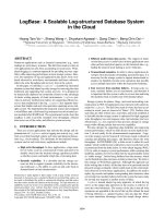
Person
- Address: CAddress
#
Name:
St i
# Age: double
+ getAge() : int
+ setAge(n)
+
getName() :
St i
+setName(s)
Class attributes :
the encapsulated
data
Class operations:
the behaviour
Attributes and operations define the state of an object
t
run-time and the capabilities or behaviour of the
bj t
Person
A simple person class
with no state or
behaviour shown
Figure 1 - Classes, attributes and operations
objects access to a unique object
instance.
Often though, an object will be
destroyed and require that it be re-
created as it was during its last active
instance. These objects require a
storage mechanism to save their
internal state and associations into and
to retrieve that state as required.
Inheritance provides the class model
with a means of factoring out common
behaviour into generalised classes that
then act as the ancestors of many
variations on a common theme.
Inheritance is a means of managing
both re-use and complexity. As we will
see, the relational model has no direct
counterpart of inheritance, which
creates a dilemma for the data
modeller mapping an object model
onto a relational framework.
Navigation from one object at run time
to another is based on absolute
references. One object has some form
of link (a pointer or unique object ID)
with which to locate or re-create the
required object.
The Relational Model
The relational data model has been
around for many years and has a
proven track record of providing
performance and flexibility. It is
essentially set based and has as its
fundamental unit the 'table', which is
composed of a set of one or more
'columns', each of which contains a
data element.
Tables and Columns
A relational table is collection of one
or more columns each of which has a
unique name within the table construct.
Each column is defined to be of a
certain basic data type, such as a
number, text or binary data. A table
definition is a template from which
table rows are created, each row being
an instance of a possible table instance.
Parent
Person
Child
A
ssociation captures
a having or using
relationship between
classes
A
class hierarchy
showing a generalised
person class from
which other classes
are derived
Family
A
ggregation captures the concept
of
collection or composition between classes
The main relationships we are
interested in are Association,
A
ggregation and Inheritance.
These
describe the ways classes interact
or relate to each
other
2
1 n
Figure 2 - UML Class model notation
Public Data Access
The relational model only offers a
public data access model. All data is
equally exposed and open to any
process to update, query or manipulate
it. Information hiding is unknown.
Behaviour
The behaviour associated with a table
is usually based on the business or
logical rules applied to that entity.
Constraints may be applied to columns
in the form of uniqueness
requirements, relational integrity
constraints to other tables/rows,
allowable values and data types.
Triggers provide some additional
behaviour that can be associated with
an entity. Typically this is used to
enforce data integrity before or after
updates, inserts and deletes.
Database stored procedures provide a
means of extending database
functionality through proprietary
language extensions used to construct
functional units (scripts). These
functional procedures do not map
directly to entities, nor have a logical
relationship to them.
Navigation through relational data sets
is based on row traversal and table
joins. SQL is the primary language
used to select rows and locate
instances from a table set.
Relationships and Identity
The primary key of a table provides the
unique identifying value for a
particular row. There are two kinds of
primary key that we are interested in:
firstly the meaningful key, made up of
data columns which have a meaning
within the business domain, and
second the abstract unique identifier,
such as a counter value, which have no
Person ID Document
Share
Address
A
Person ma
y
reside at zero
or more
addresses
A
n Address may
have zero or
more Persons in
residence
A
Person is composed of
a strict set of ID
documents (having n
elements)
A
Person ma
y
own a set of
Shares
Three forms of the Aggregation relationship. The weak form is
depicted with an unfilled diamond head, the strong form
(composition) with a filled head.
n
1
0 n
0 1
0 n
0 n
Figure 3- Aggregation Relationships
business meaning but uniquely identify
a row. We will discuss this and the
implications of meaningful keys later.
A table may contain columns that map
to the primary key of another table.
This relationship between tables
defines a foreign key and implies a
structural relationship or association
between the two tables.
Summary
From the above overview we can see
that the object model is based on
discrete entities having both state
(attributes/data) and behaviour, with
access to the encapsulated data
generally through the class public
interface only. The relational model
exposes all data equally, with limited
support for associating behaviour with
data elements through triggers, indexes
and constraints.
You navigate to distinct information in
the object model by moving from
object to object using unique object
identifiers and established object
relationships (similar to a network
data model). In the relational model
you find rows by joining and filtering
result sets using SQL using generalised
search criteria.
Identity in the object model is either a
run-time reference or persistent unique
ID (termed an OID). In the relational
world, primary keys define the
uniqueness of a data set in the overall
data space.
In the object model we have a rich set
of relationships: inheritance,
aggregation, association, composition,
dependency and others. In the
relational model we can really only
specify a relationship using foreign
keys.
Having looked at the two domains of
interest and compared some of the
important features of each, we will
digress briefly to look at the notation
proposed to represent relational data
models in the UML.
The UML Data Model Profile
The Data Model Profile is a proposed
UML extension (and currently under
review - Jan 2001) to support the
modelling of relational databases in
UML. It includes custom extensions
for such things as tables, data base
schema, table keys, triggers and
constraints. While this is not a ratified
extension, it still illustrates one
possible technique for modelling a
relational database in the UML.
Tables
Customer
A table in the UML Data Profile is a
class with the «Table» stereotype,
displayed as above with a table icon in
the top right corner.
Columns
Customer
PK OID: int
Name: VARCHAR2
A
ddress: VARCHAR2
Database columns are modelled as
attributes of the «Table» class. For
example, the figure above shows some
attributes associated with the Customer
table. In the example, an object id has
been defined as the primary key, as
well as two other columns, Name and
Address. Note that the example above
defines the column type in terms of the
native DBMS data types.
Behaviour
So far we have only defines the logical
(static) structure of the table; in
addition we should describe the
behaviour associated with columns,
including indexes, keys, triggers,
procedures & etc. Behaviour is
represented as stereotyped operations.
The figure below shows our table
above with a primary key constraint
and index, both defined as stereotyped
operations:
Customer
PK OID: int
Name: VARCHAR2
A
ddress: VARCHAR2
+ «PK» idx_customer00()
+ «index» idx_customer01()
Note that the PK flag on the column
'OID' defines the logical primary key,
while the stereotyped operation "«PK»
idx_customer00" defines the
constraints and behaviour associated
with the primary key implementation
(that is, the behaviour of the primary
key).
Adding to our example, we may now
define additional behaviour such as
triggers, constraints and stored
procedures as in the example below:
Customer
PK OID: int
Name: VARCHAR2
A
ddress: VARCHAR2
+ «PK» idx_customer00()
+ «FK» idx_customer02()
+ «Index» idx_customer01()
+ «Trigger» trg_customer00()
+ «Unique» unq_customer00()
+ «Proc» spUpdateCustomer()
+ «Check» chk_customer00()
The example illustrates the following
possible behaviour:
1. A primary key constraint (PK);
2. A Foreign key constraint (FK);
3. An index constraint (Index);
4. A trigger (Trigger);
5. A uniqueness constraint (Unique);
6. A stored procedure (Proc) - not
formally part of the data profile,
but an example of a possible
modelling technique; and a
7. Validity check (Check).
Using the notation provided above, it is
possible to model complex data
structures and behaviour at the DBMS
level. In addition to this, the UML
provides the notation to express
relationships between logical entities.
Relationships
The UML data modelling profile
defines a relationship as a dependency
of any kind between two tables. It is
represented as a stereotyped
association and includes a set of
primary and foreign keys.
The data profile goes on to require that
a relationship always involves a parent
and child, the parent defining a
primary key and the child
implementing a foreign key based on
all or part of the parent primary key.
The relationship is termed 'identifying'
if the child foreign key includes all the
elements of the parent primary key and
'non-identifying' if only some elements
of the primary key are included.
The relationship may include
cardinality constraints and be modelled
with the relevant PK - FK pair named
as association roles. Figure 4 illustrates
this kind of relationship modelling
using UML.
The Physical Model
UML also provides some mechanisms
for representing the overall physical
structure of the database, its contents
and deployed location. To represent a
physical database in UML, use a
stereotyped component as in the figure
below:
«Database»
MainOraDB
A component represents a discrete and
deployable entity within the model. In
the physical model, a component may
be mapped on to a physical piece of
hardware (a 'node' in UML).
To represent schema within the
database, use the «schema» stereotype
on a package. A table may be placed in
a «schema» to establish its scope and
location within a database.
«schema»
User
Child
Grandchild
Grandparent
Parent
Person
Mapping from the Class Model to
the Relational Model
Having described the two domains of
interest and the notation to be used, we
can now turn our attention as to how to
map or translate from one domain to
the other. The strategy and sequence
presented below is meant to be
suggestive rather than proscriptive -
adapt the steps and procedures to your
personal requirements and
Parent
Child
A
n identifying relationship between child and parent, with role names
based on primary to foreign key relationship.
PK_PersonID
2
«identifying»
FK_PersonID
0 n
Figure 4 - UML relationship
environment.
1. Model Classes
Firstly we will assume we are
engineering a new relational database
schema from a class model we have
created. This is obviously the easiest
direction as the models remain under
our control and we can optimise the
relational data model to the class
model. In the real world it may be that
you need to layer a class model on top
of a legacy data model - a more
difficult situation and one that presents
its own challenges. For the current
discussion will focus on the first
situation. At a minimum, your class
model should capture associations,
inheritance and aggregation between
elements.
2. Identify persistent objects
Having built our class model we need
to separate it into those elements that
require persistence and those that do
not. For example, if we have designed
our application using the Model-View-
Controller design pattern, then only
classes in the model section would
require persistent state.
3. Assume each persistent class maps
to one relational table
A fairly big assumption, but one that
works in most cases (leaving the
inheritance issue aside for the
moment). In the simplest model a class
from the logical model maps to a
relational table, either in whole or in
part. The logical extension of this is
that a single object (or instance of a
class) maps to a single table row.
4. Select an inheritance strategy
Inheritance is perhaps the most
problematic relationship and logical
construct from the object-oriented
model that requires translating into the
relational model. The relational space
is essentially flat, every entity being
complete in its self, while the object
model is often quite deep with a well-
developed class hierarchy.
The deep class model may have many
layers of inherited attributes and
behaviour, resulting in a final, fully
featured object at run-time. There are
three basic ways to handle the
translation of inheritance to a relational
model:
1. Each class hierarchy has a single
corresponding table that contains
all the inherited attributes for all
elements - this table is therefore the
union of every class in the
hierarchy. For example, Person,
Parent, Child and Grandchild may
all form a single class hierarchy,
and elements from each will appear
in the same relational table;
2. Each class in the hierarchy has a
corresponding table of only the
attributes accessible by that class
(including inherited attributes). For
example, if Child is inherited from
Person only, then the table will
contain elements of Person and
Child only;
3. Each generation in the class
hierarchy has a table containing
only that generation's actual
attributes. For example, Child will
map to a single table with Child
attributes only
There are cases to be made for each
approach, but I would suggest the
simplest, easiest to maintain and less
error prone is the third option. The first
option provides the best performance
at run-time and the second is a
compromise between the first and last.
The first option flattens the hierarchy
and locates all attributes in one table -
convenient for updates and retrievals
of any class in the hierarchy, but
difficult to authenticate and maintain.
Business rules associated with a row
are hard to implement, as each row
may be instantiated as any object in the
hierarchy. The dependencies between
columns can become quite
complicated. In addition, an update to
any class in the hierarchy will
potentially impact every other class in
the hierarchy, as columns are added,
deleted or modified from the table.
The second option is a compromise
that provides better encapsulation and
eliminates empty columns. However, a
change to a parent class may need to
be replicated in many child tables.
Even worse, the parental data in two or
more child classes may be redundantly
stored in many tables; if a parent's
attributes are modified, there is
considerable effort in locating
dependent children and updating the
affected rows.
The third option more accurately
reflects the object model, with each
class in the hierarchy mapped to its
own independent table. Updates to
parents or children are localised in the
correct space. Maintenance is also
relatively easier, as any modification
of an entity is restricted to a single
relational table also. The down side is
the need to re-construct the hierarchy
at run-time to accurately re-create a
tbl_Parent
AddressOID: VARCHAR
Name: VARCHAR
PK OID: VARCHAR
Sex: VARCHAR
Parent
- OID: GUID
# Name: String
# Sex: Gender
+ setName(String)
+ getName() : String
+ setSex(String)
+ getSex() : String
Address
- OID: GUID
# City: String
# Phone: String
# State: String
# Street: String
+ getCity() : String
+ getStreet() : String
+ setCity(String)
+ setStreet(String)
tbl_Address
City: VARCHAR
PK OID: VARCHAR
Phone: VARCHAR
State: VARCHAR
Street: VARCHAR
The Address association from the logical model becomes
a foreign key relationship in the data model
A Parent class with unique ID (OID)
and Name and Sex attributes maps to
a relational table.
The Address class in the logical
model becomes a table in the
data model
<<realises>>
m_Address 0 n
1
<<realises>>
Figure 5 - Class to Table mapping
child class's state. A Child object may
require a Person member variable to
represent their model parentage. As
both require loading, two database
calls are required to initialise one
object. As the hierarchy deepens, with
more generations, the number of
database calls required to initialise or
update a single object increases.
It is important to understand the issues
that arise when you map inheritance
onto a relational model, so you can
decide which solution is right for you.
5. For each class add a unique
object identifier
In both the relational and the object
world, there is the need to uniquely
identify an object or entity.
In the object model, non-persistent
objects at run-time are typically
identified by direct reference or by a
pointer to the object. Once an object is
created, we can refer to it by its run-
time identity. However, if we write out
an object to storage, the problem is
how to retrieve the exact same instance
on demand.
The most convenient method is to
define an OID (object identifier) that is
guaranteed to be unique in the
namespace of interest. This may be at
the class, package or system level,
depending on actual requirements.
An example of a system level OID
might be a GUID (globally unique
identifier) created with Microsoft's
'guidgen' tool; eg. {A1A68E8E-CD92-
420b-BDA7-118F847B71EB}. A class
level OID might be implemented using
a simple numeric (eg. 32 bit counter).
If an object holds references to other
objects, it may do so using their OID.
A complete run-time scenario can then
be loaded from storage reasonably
efficiently.
An important point about the OID
values above is that they have no
inherent meaning beyond simple
identity. They are only logical pointers
and nothing more. In the relational
model, the situation is often quite
different.
Identity in the relational model is
normally implemented with a primary
key. A primary key is a set of columns
in a table that together uniquely
identify a row. For example, name and
address may uniquely identify a
'Customer'. Where other entities, such
as a 'Salesperson', reference the
'Customer', they implement a foreign
key based on the 'Customer' primary
key.
The problem with this approach for our
purposes is the impact of having
business information (such as customer
name and address) embedded in the
identifier. Imagine three or four tables
all have foreign keys based on the
customer primary key, and a system
change requires the customer primary
key to change (for example to include
'customer type'). The work required to
modify both the 'customer' table and
the entities related by foreign key is
quite large.
On the other hand, if an OID was
implemented as the primary key and
formed the foreign key for other tables,
the scope of the change is limited to
the primary table and the impact of the
change is therefore much less.
Also, in practice, a primary key based
on business data may be subject to
change. For example a customer may
change address or name. In this case
the changes must be propagated
correctly to all other related entities,
not to mention the difficulty of
changing information that is part of the
primary key.
An OID always refers to the same
entity - no matter what other
information changes. In the above
example, a customer may change name
or address and the related tables
require no change.
When mapping object models into
relational tables, it is often more
convenient to implement absolute
identity using OID's rather than
business related primary keys. The
OID as primary and foreign key
approach will usually give better load
and update times for objects and
minimise maintenance effort. In
practice, a business related primary
key might be replaced with:
1. A uniqueness constraint or index
on the columns concerned;
2. Business rules embedded in the
class behaviour;
3. A combination of 1 and 2.
Again, the decision to use meaningful
keys or OID's will depend on the exact
requirements of the system being
developed.
6. Map attributes to columns
In general we will map the simple data
attributes of a class to columns in the
relational table. For example a text and
number field may represent a person's
name and age respectively. This sort of
direct mapping should pose no
problem - simply select the appropriate
data type in the vendor's relational
model to host your class attribute.
For complex attributes (ie. attributes
that are other objects) use the approach
detailed below for handling
associations and aggregation.
7. Map associations to foreign keys
More complex class attributes (ie.
those which represent other classes),
are usually modelled as associations.
An association is a structural
relationship between objects. For
example, a Person may live at an
Address. While this could be modelled
as a Person has City, Street and Zip
attributes, in both the object and the
relational world we are inclined to
structure this information as a separate
entity, an Address.
In the object domain an address
represents a unique physical object,
possibly with a unique OID. In the
relational, an address may be a row in
an Address table, with other entities
having a foreign key to the Address
primary key.
In both models then, there is the
tendency to move the address
information into a separate entity. This
helps to avoid redundant data and
improves maintainability.
So for each association in the class
model, consider creating a foreign key
from the child to the parent table.
8. Map Aggregation and
Composition
Aggregation and composition
relationships are similar to the
association relationship and map to
tables related by primary-foreign key
pairs. There are however, some points
to bear in mind.
Ordinary aggregation (the weak form)
models relationships such as a Person
resides at one or more Addresses. In
this instance, more than one person
could live at the same address, and if
the Person ceased to exist, the
Addresses associated with them would
still exist. This example parallels the
many-to-many relationship in
relational terminology, and is usually
implemented as a separate table
containing a mapping of primary keys
from one table to the primary keys of
another.
A second example of the weak form of
aggregation is where an entity has use
or exclusive ownership of another. For
example, a Person entity aggregates a
set of shares. This implies a Person
may be associated with zero or more
shares from a Share table, but each
Share may be associated with zero or
one Person. If the Person ceases to
exist, the Shares become un-owned or
are passed to another Person. In the
relational world, this could be
implemented as each Share having an
'owner' column which stored a Person
ID (or OID) .
The strong form of aggregation,
however, has important integrity
constraints associated with it.
Composition, implies that an entity is
composed of parts, and those parts
have a dependent relationship to the
whole. For example, a Person may
have identifying documents such as a
Passport, Birth Certificate, Driver's
License & etc. A Person entity may be
composed of the set of such identifying
documents. If the Person is deleted
from the system, then the identifying
documents must be deleted also, as
they are mapped to a unique
individual.
If we ignore the OID issue for the
moment, a weak aggregation could be
implemented using either an
intermediate table (for the many-to-
Customer
PK OID: int
Name: VARCHAR2
Address: VARCHAR2
Salesperson: int
+ «PK» PK_Customer()
+ «FK» FK_SalesPerson()
Salesperson
PK OID: int
Name: VARCHAR2
Department: VARCHAR2
+ «PK» PK_Salesperson()
Relationships are based on the PK- FK pair. This example relates a Salesperson to a
Customer by the appropriate primary and foreign keys. The assumption is that a
customer may only be associated with one salesperson.
PK_Salesperson
1
FK_Salesperson
0 *
Figure 6 - Table relationships in UML
many case) or with a foreign key in the
aggregated class/table (one-to-many
case). In the case of the many-to-many
relationship, if the parent is deleted,
the entries in the intermediate table for
that entity must also be deleted also. In
the case of the one-to-many
relationship, if the parent is deleted,
the foreign key entry (ie. 'owner') must
be cleared.
In the case of composition, the use of a
foreign key is mandatory, with the
added constraint that on deletion of the
parent the part must be deleted also.
Logically there is also the implication
with composition that the primary key
of the part forms part of the primary
key of the whole - for example, a
Person's primary key may composed of
their identifying documents ID's. In
practice this would be cumbersome,
but the logical relationship holds true.
9. Define relationship roles
For each association type relationship,
each end of the relationship may be
further specified with role information.
Typically, you will include the Primary
Key constraint name and the Foreign
Key Constraint name. Figure 6
illustrates this concept. This logically
defines the relationship between the
two classes.
In addition, you may specify additional
constraints (eg. {Not NULL}) on the
role and cardinality constraints (eg.
0 n).
10. Model behaviour
We now come to another difficult
issue: whether to map some or all class
behaviour to the functional capabilities
provided by database vendors in the
form of triggers, stored procedures,
uniqueness and data constraints, and
relational integrity.
A non-persistent object model would
typically implement all the behaviour
required in one or more programming
languages (eg. Java or C++). Each
class will be given its required
behaviour and responsibilities in the
form of public, protected and private
methods.
Relational databases from different
vendors typically include some form of
programmable SQL based scripting
language to implement data
manipulation. The two common
examples are triggers and stored
procedures.
When we mix the object and relational
models, the decision is usually whether
to implement all the business logic in
the class model, or to move some to
the often more efficient triggers and
stored procedures implemented in the
relational DBMS.
From a purely object-oriented point of
view, the answer is obviously to avoid
triggers and stored procedures and
place all behaviour in the classes. This
localises behaviour, provides for a
cleaner design, simplifies maintenance
and provides good portability between
DBMS vendors.
In the real world, the bottom line may
be scaling to 100's or 1000's of
transactions per second, something
stored procedures and triggers are
purpose designed for.
If purity of design, portability,
maintenance and flexibility are the
main drivers, localise all behaviour in
the object methods.
If performance is an over-riding
concern, consider delegating some
behaviour to the more efficient DBMS
scripting languages. Be aware though
that the extra time taken to integrate
the object model with the stored
procedures in a safe way, including
issues with remote effects and
debugging, may cost more in
development time than simply
deploying to more capable hardware.
As mentioned earlier, the UML Data
Profile provides the following
extensions (stereotyped operations)
with which you can model DBMS
behaviour:
! Primary key constraint (PK);
! Foreign key constraint (FK);
! Index constraint (Index);
! Trigger (Trigger);
! Uniqueness constraint (Unique);
! Validity check (Check).
11. Produce a physical model
In UML, the physical model describes
how something will be deployed into
the real world - the hardware platform,
network connectivity, software,
operating system, dll's and other
components. You produce a physical
model to complete the cycle - from an
initial use case or domain model,
through the class model and data
models and finally the deployment
model.
Typically for this model you will
create one or more nodes that will host
the database(s) and place DBMS
software components on them. If the
database is split over more than one
DBMS instance, you can assign
packages («schema») of tables to a
single DBMS component to indicate
where the data will reside.
Conclusion
This concludes this short article on
database modelling using the UML. As
MainServer
«schema»
System
sys_aliases
sys_procs
sys_queries
sys_tables
sys_users
«schema»
Us e r
Child
Grandchild
Grandparent
Par ent
Per s on
«Database»
MainOraDB
A Node is a physical piece of hardw are (such as a Unix server) on w hich components are deployed. The
database component in this example is also mapped to tw o logical «schema», each of w hich contains a
number of tables.
Figure 7 - The Physical Model
you can see, there are quite a few
issues to consider when mapping from
the object world to the relational. The
UML provides support for bridging the
gap between both domains, and
together with extensions such as the
UML Data Profile is a good language
for successfully integrating both
worlds.
References
Muller, Robert J., Database Design for
Smarties, Morgan Kaufman, 1999.
Rational Software, The UML and Data
Modelling, Rational Software
Ambler, Scott W., Mapping Objects to
Relational Databases, AmbySoft inc,
1999
About the Author
Geoffrey Sparks is the director of
Sparx Systems, an Australian company
that specialises in UML tools.
The Sparx Systems web site is at:
www.sparxsystems.com.au
Geoffrey may be contacted at
A quick summary guide to data modelling in UML
1. Create a class model for your development domain
2. Identify persistent classes from the model
3. Assume each persistent class in the model will map to one relational table
4. Select a suitable inheritance strategy for each class hierarchy
5. For each class add a unique ID (OID) or select a suitable primary key
6. For each class map simple data types to table columns
7. For each class, map complex attributes (association, aggregation) to PK/ FK pairs. Take
special note of the strong and weak forms of aggregation.
8. For related classes, map PK, FK pairs naming the role ends according to selected key.
9. Label relationship roles with their appropriate cardinality and stereotype: <<identifying>>
or <<non-identifying>>
10. Add stereotyped operations for table behaviour (keys, indexes, uniqueness, checks, and
triggers)
11. Divide persistent classes into logical schema
12. Create a deployment model and link database components to physical nodes