Ebook Fundamentals of building construction: Materials and methods (Fifth edition) - Part 2
Bạn đang xem bản rút gọn của tài liệu. Xem và tải ngay bản đầy đủ của tài liệu tại đây (36.38 MB, 508 trang )
12
Light Gauge
Steel Frame
Construction
• The Concept of Light Gauge
Steel Construction
CONSIDERATIONS
SUSTAINABILITY IN
LIGHT GAUGE STEEL FRAMING
OF
• Framing Procedures
• Other Common Uses of
Light Gauge Steel Framing
• Light Gauge Steel Framing
and the Building Codes
• Finishes for Light Gauge
Steel Framing
METALS IN ARCHITECTURE
FROM CONCEPT TO REALITY
Camera Obscura at Mitchell Park,
Greenport, New York
FOR PRELIMINARY
DESIGN OF A LIGHT
GAUGE STEEL FRAME STRUCTURE
• Advantages and
Disadvantages of Light
Gauge Steel Framing
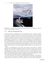
Driving self-drilling, self-tapping screws with electric screw guns, framers add diagonal
bracing straps to a wall frame made from light gauge steel studs and runner channels.
(Courtesy of United States Gypsum Company)
489
JWBK274_Ch12.indd 489
10/30/08 4:30:34 AM
To manufacture the members used in light gauge steel frame
construction, sheet steel is fed from continuous coils through
machines at room temperature that cold-work the metal (see
Chapter 11) and fold it into efficient structural shapes, producing
linear members that are stiff and strong. Thus, these members
are referred to as cold-formed metal framing to differentiate them
from the much heavier hot-rolled shapes that are used in structural steel framing. The term “light gauge” refers to the relative
thinness (gauge) of the steel sheet from which the members are
made.
The Concept of
Light Gauge Steel
Construction
Light gauge steel construction is the
noncombustible equivalent of wood
light frame construction. The external dimensions of the standard sizes
of light gauge members correspond
closely to the dimensions of the standard sizes of nominal 2-inch (38-mm)
framing lumber. These steel members
are used in framing as closely spaced
studs, joists, and rafters in much the
same way as wood light frame members are used, and a light gauge steel
frame building may be sheathed, insulated, wired, and Þnished inside
and out in the same manner as a
wood light frame building.
The steel used in light gauge
members is manufactured to ASTM
standard A1003 and is metalliccoated with zinc or aluminum-zinc
alloy to provide long-term protection
against corrosion. The thickness of
the metallic coating can be varied,
depending on the severity of the environment in which the members will
be placed. For studs, joists, and rafters, the steel is formed into C-shaped
cee sections (Figure 12.1). The webs of
cee members are punched at the factory to provide holes at 2-foot (600mm) intervals; these are designed to
allow wiring, piping, and bracing to
pass through studs and joists without
the necessity of drilling holes on the
construction site. For top and bottom wall plates and for joist headers,
channel sections are used. The strength
and stiffness of a member depend
on the shape and depth of the section and the gauge (thickness) of the
steel sheet from which it is made. A
standard range of depths and gauges
is available from each manufacturer.
Commonly used metal thicknesses
for loadbearing members range from
0.097 to 0.033 inch (2.46Ð0.84 mm)
and are as thin as 0.018 inch (0.45
mm) for nonloadbearing members
(Figure 12.2).
At least one manufacturer produces nonloadbearing light gauge
steel members by passing steel sheet
through rollers with mated patterned
surfaces, producing a dense array of
dimples in the metal of the formed
members. The additional cold working of the metal that occurs during
the forming process and the Þnished
Figure 12.1
Typical light gauge steel framing members. To the left are the common sizes of cee
studs and joists. In the center are channel studs. To the right are runner channels.
490
JWBK274_Ch12.indd 490
10/30/08 4:30:36 AM
The Concept of Light Gauge Steel Construction
/ 491
CONSIDER ATIONS OF SUSTAINABILITY
IN LIGHT GAUGE STEEL FRAMING
In addition to the sustainability issues raised in the previous chapter, which also apply here, the largest issue concerning the sustainability of light gauge steel construction
is the high thermal conductivity of the framing members.
If a dwelling framed with light gauge steel members is
framed, insulated, and Þnished as if it were framed with
wood, it will lose heat in winter at about double the rate
of the equivalent wood structure. To overcome this limitation, energy codes now require light gauge steel framed
buildings constructed in cold regions, including most of
the continental United States, to be sheathed with plastic
foam insulation panels in order to eliminate the extensive
thermal bridging that can otherwise occur through the
steel framing members.
patterned surface result in members
made from thinner sheet stock that are
equal in and strength and stiffness to
conventionally formed members produced from heavier gauge material.
For large projects, members may
be manufactured precisely to the required lengths. Otherwise, they are
furnished in standard lengths. Members may be cut to length on the
construction job site with power saws
or special shears. A variety of sheet
metal angles, straps, plates, channels,
and miscellaneous shapes are manufactured as accessories for light gauge
steel construction (Figure 12.3).
Light gauge steel members are
usually joined with self-drilling, selftapping screws, which drill their own
holes and form helical threads in the
holes as they are driven. Driven rapidly by hand-held electric or pneumatic tools, these screws are plated
with cadmium or zinc to resist corrosion, and they are available in an
assortment of diameters and lengths
Figure 12.2
Minimum thicknesses of base sheet
metal (not including the metallic coating)
for light gauge steel framing members.
Traditional gauge designations are also
included (note how lower gauge numbers
correspond to greater metal thickness).
Gauge numbers are no longer recommended for specification of sheet metal
thickness due to lack of a uniform standard for the translation between these
numbers and actual metal thickness.
Sheet metal thickness may also be specified in mils, or thousandths of an inch.
For example, a thickness of 0.033 inch
can be expressed as 33 mils.
JWBK274_Ch12.indd 491
Even with insulating sheathing, careful attention
must be given to avoid undesired thermal bridges. For
example, on a building with a sloped roof, a signiÞcant
thermal bridge may remain through the ceiling joist-rafter
connections, as seen in Figure 12.4b. Foam sheathing on
the inside wall and ceiling surfaces is one possible way to
avoid this condition, but adding insulation to the inside
of the metal framing exposes the studs and stud cavities
to greater temperature extremes and increases the risk of
condensation. It also still allows thermal bridging through
the screws used to fasten interior gypsum wallboard to the
framing. Though small in area, these thermal bridges can
readily conduct heat and result in spots of condensation
on interior Þnish surfaces in very cold weather.
to suit a full range of connection situations. Welding is often employed to
assemble panels of light gauge steel
framing that are prefabricated in a
factory, and it is sometimes used on
the building site where particularly
strong connections are needed. Other fastening techniques that are widely used include hand-held clinching
devices that join members without
screws or welds and pneumatically
driven pins that penetrate the members and hold by friction.
Minimum Thickness of Steel Sheet
Gauge
12
14
16
18
20
22
25
Loadbearing Light
Gauge Steel Framing
0.097Љ (2.46 mm)
0.068Љ (1.73 mm)
0.054Љ (1.37 mm)
0.043Љ (1.09 mm)
0.033Љ (0.84 mm)
Nonloadbearing Light
Gauge Steel Framing
0.054Љ (1.37 mm)
0.043Љ (1.09 mm)
0.030Љ (0.75 mm)
0.027Љ (0.69 mm)
0.018Љ (0.45 mm)
10/30/08 4:30:39 AM
492 /
Chapter 12 • Light Gauge Steel Frame Construction
Figure 12.3
END CLIPS
WEB STIFFENER
Standard accessories for light gauge
steel framing. End clips are used to join
members that meet at right angles. Foundation clips attach the ground-floor platform to anchor bolts embedded in the
foundation. Joist hangers connect joists
to headers and trimmers around openings. The web stiffener is a two-piece
assembly that is inserted inside a joist
and screwed to its vertical web to help
transmit wall loads vertically through the
joist. The remaining accessories are used
for bracing.
FOUNDATION CLIP
V-BRACING
FLAT STRAP BRACING
JOIST HANGER
1 1/2" COLD ROLLED CHANNEL
Framing Procedures
The sequence of construction for
a building that is framed entirely
with light gauge steel members is
essentially the same as that described
in Chapter 5 for a building framed
with nominal 2-inch (38-mm) wood
members (Figure 12.4). Framing is
usually constructed platform fashion: The ground ßoor is framed with
steel joists. Mastic adhesive is applied
to the upper edges of the joists, and
wood panel subßooring is laid down
and fastened to the upper ßanges of
the joists with screws. Steel studs are
laid ßat on the subßoor and joined
JWBK274_Ch12.indd 492
to make wall frames. The wall frames
are sheathed either with wood panels
or, for noncombustible construction,
with gypsum sheathing panels, which are
similar to gypsum wallboard but with
glass mat faces and a water-resistant
core formulation. The wall frames are
tilted up, screwed down to the ßoor
frame, and braced. The upper-ßoor
platform is framed, then the upperßoor walls. Finally, the ceiling and roof
are framed in much the same way as in
a wood-framed house. Prefabricated
trusses of light gauge steel members
that are screwed or welded together
are often used to frame ceilings and
roofs (Figures 12.15 and 12.16). It is
possible, in fact, to frame any building with light gauge steel members
that can be framed with nominal
2-inch (38-mm) wood members.
To achieve a more Þre-resistive
construction type under the building code, ßoors of corrugated steel
decking with a concrete topping
are sometimes substituted for wood
panel subßooring.
Openings in ßoors and walls are
framed analogously to openings in
wood light frame construction, with
doubled members around each opening and strong headers over doors
and windows (Figures 12.5Ð12.9).
Joist hangers and right-angle clips of
10/30/08 4:30:40 AM
Framing Procedures
Steel
/ 493
joist roof r
afters
End clip
Ridge beam—
nested steel joists
Anchor clip
Steel joist roof rafter
Steel joist soffit
framing
B EAVE
A RIDGE
Stud
Figure 12.4
Runner
Typical light gauge framing details. Each detail is keyed
by letter to a circle on the whole-building diagram in the
center of the next page to show its location in the frame.
(a) A pair of nested joists makes a boxlike ridge board or
ridge beam. (b) Anchor clips are sandwiched between the
ceiling joists and rafters to hold the roof framing down to
the wall. (c) A web stiffener helps transmit vertical forces
from each stud through the end of the joist to the stud in
the floor below. Mastic adhesive cushions the joint between
the subfloor and the steel framing. (d) Foundation clips
anchor the entire frame to the foundation. (e) At interior
joist bearings, joists are overlapped back to back and a web
stiffener is inserted.
(continued)
Continuous bead of
adhesive
Web stiffener
Closure
channel
C-runner
C JOIST BEARING AT UPPER FLOOR
Runner—fasten
through plywood
into closure
Plywood subfloor
Web stiffener
Steel joists
Grout and shim as
required
Web stiffener
Foundation clip
D JOIST BEARING AT FOUNDATION
JWBK274_Ch12.indd 493
Steel stud or beam
E INTERIOR JOIST BEARING
10/30/08 4:30:40 AM
494 /
Chapter 12 • Light Gauge Steel Frame Construction
Ceiling joists
Rafter
Steel stud
A
H GABLE END FRAMING
Closure
channel or
joist section
B
H
1 1/2" x 20gauge bracing
strap
C
D
End tabs
E
G
F
G JOIST PARALLEL TO END WALL
Closure channel or
joist section
Figure 12.4 (continued)
( f, g) Short crosspieces brace the last joist at the end of the
building and help transmit stud forces through to the wall
below. (h) Like all these details, the gable end framing is
directly analogous to the corresponding detail for a wood
light frame building as shown in Chapter 5.
F JOIST PARALLEL TO FOUNDATION
JWBK274_Ch12.indd 494
10/30/08 4:30:40 AM
Framing Procedures
Opening
Joist hanger
Double joist header
(nested)
Steel joist framing into
header
/ 495
Figure 12.5
Headers and trimmers for floor openings
are doubled and nested to create a strong,
stable box member. Only one vertical
flange of the joist hanger is attached
to the joist; the other flange would be
used instead if the web of the joist were
oriented to the left rather than the right.
Double joist trimmer
(nested)
Figure 12.6
Steel gusset plate
Runner channel
Lintel—2 steel joists
A typical window or door head detail. The header is made of
two joists placed with their open sides together. The top plate
of the wall, which is a runner channel, continues over the top
of the header. Another runner channel is cut and folded at each
end to frame the top of the opening. Short studs are inserted
between this channel and the header to maintain the rhythm of
the studs in the wall.
Steel stud
JWBK274_Ch12.indd 495
10/30/08 4:30:40 AM
496 /
Chapter 12 • Light Gauge Steel Frame Construction
Figure 12.7
Diagonal strap braces stabilize upperfloor wall framing for an apartment
building. (Courtesy of United States Gypsum
Company)
Figure 12.8
Temporary braces support the walls at
each level until the next floor platform
has been completed. Cold-rolled
channels pass through the web openings
of the studs; they are welded to each stud
to help stabilize them against buckling.
(Courtesy of Unimast Incorporated—
www.unimast.com)
JWBK274_Ch12.indd 496
10/30/08 4:30:40 AM
Framing Procedures
/ 497
Figure 12.9
A detail of a window header. Because a
supporting stud has been inserted under
the end of the header, a large gusset
plate such as the one shown in Figure
12.6 is not required. (Courtesy of Unimast
Incorporated—www.unimast.com)
Figure 12.10
Ceiling joists in place for an apartment
building. A brick veneer cladding has
already been added to the ground floor.
(Courtesy of United States Gypsum Company)
JWBK274_Ch12.indd 497
10/30/08 4:30:42 AM
498 /
Chapter 12 • Light Gauge Steel Frame Construction
sheet steel are used to join members
around openings. Light gauge members are designed so that they can be
nested to form a tubular conÞguration
that is especially strong and stiff when
used for a ridge board or header
(Figures 12.4a and 12.5).
Because light gauge steel members are much more prone than their
wood counterparts to twisting or buckling under load, somewhat more attention must be paid to their bracing and
bridging. The studs in tall walls are
generally braced at 4-foot (1200-mm)
intervals, either with steel straps
screwed to the edges of the studs or
with 1½-inch (38-mm) cold-formed
steel channels passed through the
punched openings in the studs and
welded or screwed to an angle clip at
each stud (Figure 12.8). Floor joists
are bridged with cee-joist blocking
between and steel straps screwed to
their top and bottom edges. In locations where large vertical forces must
pass through ßoor joists (as occurs
where loadbearing studs sit on the
edge of a ßoor platform), steel web
stiffeners are screwed to the thin webs
of the joists to prevent them from
buckling (Figure 12.4c,e). Wall bracing consists of diagonal steel straps
screwed to the studs (chapter-opening
photo, Figure 12.7). Permanent resistance to buckling, twisting, and lateral
loads such as wind and earthquake is
imparted largely and very effectively
by subßooring, wall sheathing, and
interior Þnish materials.
Figure 12.11
A detail of eave framing. (Courtesy of
Unimast Incorporated—www.unimast.com)
Figure 12.12
A power saw with an abrasive blade
cuts quickly and precisely through steel
framing members. (Courtesy of Unimast
Incorporated—www.unimast.com)
JWBK274_Ch12.indd 498
10/30/08 4:30:43 AM
Other Common Uses of Light Gauge Steel Framing
Other Common Uses
of Light Gauge Steel
Framing
Light gauge steel members are used
to construct many components of
Þre-resistant buildings whose structures
are made of structural steel, concrete,
or masonry. These components include
interior walls and partitions (Chapter
23), suspended ceilings (Chapter 24),
and fascias, parapets, and backup walls
for such exterior claddings as masonry
veneer, exterior insulation and Þnish
system (EIFS), glass-Þber-reinforced
concrete (GFRC), metal panels, and
various thin stone cladding systems
(Chapters 19 and 20; see also Figures
12.13 and 12.14). Light gauge steel
members used for framing interior partitions and other nonloadbearing applications are properly referred to and
speciÞed as nonstructural metal framing,
as distinct from cold-formed metal framing, the latter term reserved for light
gauge steel members used in structural
applications and exterior wall cladding
systems (even though both types of
members are, in fact, cold-formed).
Light gauge steel studs can be combined with concrete to produce thin,
but relatively stiff, wall panel systems.
Both loadbearing and nonloadbearing
panels can be made that are suitable for
use in residential and light commercial
/ 499
buildings. A variety of production
methods are possible that generally involve casting an approximately 2-inch
(50-mm)-thick concrete facing onto a
framework of steel studs. The concrete
may be sitecast (on the building site) or
precast (in a factory). The concrete-tosteel bond may be created by a variety of
devices welded or screwed to the studs
that then become embedded in the
concrete, such as stud anchors, sheet
metal shear strips, welded wire reinforcing, or expanded metal. In loadbearing applications, the concrete panels
provide shear resistance while the steel
studs provide most of the resistance to
gravity loads and to wind loads acting
perpendicular to the face of the panel.
Figure 12.13
Light gauge steel stud walls frame the exterior walls of a building whose floors and
roof are framed with structural steel. (Courtesy of Unimast Incorporated—www.unimast.
com)
JWBK274_Ch12.indd 499
10/30/08 4:30:44 AM
500 /
Chapter 12 • Light Gauge Steel Frame Construction
Figure 12.14
The straightness of steel studs is apparent
in these tall walls that enclose a building
framed with structural steel.
(Courtesy of Unimast Incorporated—
www.unimast.com)
JWBK274_Ch12.indd 500
10/30/08 4:30:45 AM
Other Common Uses of Light Gauge Steel Framing
/ 501
Figure 12.15
A worker tightens the last screws to
complete a connection in a light gauge
steel roof truss. The truss members are
held in alignment during assembly by a
simple jig made of plywood and blocks
of framing lumber. (Courtesy of Unimast
Incorporated—www.unimast.com)
Figure 12.16
Installing steel roof trusses. (Courtesy of
Unimast Incorporated—www.unimast.com)
JWBK274_Ch12.indd 501
10/30/08 4:30:46 AM
502 /
Chapter 12 • Light Gauge Steel Frame Construction
FOR PRELIMINARY DESIGN OF A LIGHT GAUGE STEEL FRAME STRUCTURE
¥ Estimate the depth of rafters on the basis of the horizontal (not slope) distance from the outside wall of the building to the ridge board in a gable or hip roof and the horizontal distance between supports in a shed roof. Estimate
the depth of a rafter at 1ր24 of this span, rounded up to the
nearest 2-inch (50-mm) dimension.
¥ The depth of light gauge steel roof trusses is usually
based on the desired roof pitch. A typical depth is onequarter of the width of the building, which corresponds to
a 6ր12 pitch.
¥ Estimate the depth of light gauge steel floor joists as 1ր20
of the span, rounded up to the nearest 2-inch (50-mm) dimension.
¥ For loadbearing studs, add up the total width of ßoor
and roof slabs that contribute load to the stud wall. A 35ր8
-inch (92-mm) or 4-inch (102-mm) stud wall can support
a combined width of approximately 60 feet (18 m), and a
6-inch (152-mm) or 8-inch (203-mm) stud wall can support
a combined width of approximately 150 feet (45 m).
In situations where noncombustibility is not a requirement, metal and
wood light framing are sometimes
mixed in the same building. Some
builders Þnd it economical to use
wood to frame exterior walls, ßoors,
and roof, with steel framing for interior
partitions. Sometimes all walls, interior and exterior, are framed with steel,
and ßoors are framed with wood. Steel
trusses made of light gauge members
may be applied over wood frame walls.
In such mixed uses, special care must
be taken in the details to ensure that
wood shrinkage will not create unforeseen stresses or damage to Þnish materials. Steel framing also may be used in
lieu of wood where the risk of damage
from termites is very high.
Advantages and
Disadvantages of
Light Gauge Steel
Framing
Light gauge steel framing shares
most of the advantages of wood light
JWBK274_Ch12.indd 502
¥ For exterior cladding backup walls, estimate that a
3 5ր8 -inch (92-mm) stud may be used to a maximum height
of 12 feet (3.7 m), a 6-inch (150-mm) stud to 19 feet
(5.8 m), and an 8-inch (100-mm) stud to 30 feet (9.1 m).
For brittle cladding materials such as brick masonry, select
a stud that is 2 inches (50 mm) deeper than these numbers
would indicate.
All framing members are usually spaced at 24 inches
(600 mm) o.c.
These approximations are valid only for purposes of
preliminary building layout and must not be used to select
Þnal member sizes. They apply to the normal range of
building occupancies such as residential, ofÞce, commercial,
and institutional buildings. For manufacturing and storage
buildings, use somewhat larger members.
For more comprehensive information on preliminary
selection and layout of structural members, see Edward
Edward and Joseph Iano, The Architect’s Studio Companion
(4th ed.), New York, John Wiley & Sons, Inc., 2007.
framing: It is versatile and ßexible;
requires only simple, inexpensive tools;
furnishes internal cavities for utilities
and thermal insulation; and accepts an
extremely wide range of exterior and
interior Þnish materials. Additionally,
steel framing may be used in buildings
for which noncombustible construction is required by the building code,
thus extending its use to larger buildings and those whose uses require a
higher degree of resistance to Þre.
Steel framing members are signiÞcantly lighter in weight than the wood
members to which they are structurally
equivalent, an advantage that is often
enhanced by spacing steel studs, joists,
and rafters at 24 inches (600 mm) o.c.
rather than 16 inches (400 mm) o.c.
Light gauge steel joists and rafters can
span slightly longer distances than nominal 2-inch (50-mm) wood members of
the same depth. Steel members tend to
be straighter and more uniform than
wood members, and they are much
more stable dimensionally because they
are unaffected by changing humidity.
Although they may corrode if exposed
to moisture over an extended period of
time, particularly in oceanfront locations, steel framing members cannot
fall victim to termites or decay.
Compared to walls and partitions
of masonry construction, equivalent
walls and partitions framed with steel
studs are much lighter in weight, easier
to insulate, and accept electrical wiring and pipes for plumbing and heating much more readily. Steel framing,
because it is a dry process, may be carried out under wet or cold weather
conditions that would make masonry
construction difÞcult. Masonry walls
tend to be much stiffer and more resistant to the passage of sound than steelframed walls, however.
The thermal conductivity of light
gauge steel framing members is much
higher than that of wood. In cold regions, light gauge steel framing should
be detailed with thermal breaks, that
is, materials with high resistance to
the ßow of heat, such as foam plastic
sheathing or insulating edge spacers
between studs and sheathing, to prevent the rapid loss of heat through the
steel members. Without such measures,
the thermal performance of the wall or
10/30/08 4:30:47 AM
Finishes for Light Gauge Steel Framing
roof is greatly reduced, energy losses
increase substantially, and moisture
condensation within the framing cavity or on interior building surfaces may
occur, with attendant damage to materials, growth of mold and mildew, and
discoloration of surface Þnishes. Special attention must be given to designing details to block excessive heat ßow
in every area of the frame. At the eave
of a steel-framed house, for instance,
the ceiling joists readily conduct heat
from the warm interior ceiling along
their length to the cold eave unless
insulating edge spacers or foam insulation boards are used between the ceiling Þnish material and the joists.
Light Gauge Steel
Framing and the
Building Codes
Although light gauge steel framing
members will not burn, they will lose
their structural strength and stiffness
rapidly if exposed to the heat of Þre.
They must therefore be protected
from Þre in accordance with building code requirements. With suitable protection provided by gypsum
sheathing and gypsum wallboard or
plaster, light gauge steel construction
may be classiÞed as either Type I or
Type II Construction in the building code table shown in Figure 1.2,
enabling its use for a wide range of
building types and sizes.
In its International Residential Code for One- and Two-Family
Dwellings, the International Code
Council has incorporated prescriptive requirements for steel-framed
residential construction. In many
cases, these requirements, with their
structural tables and standard details, allow builders to design and
construct light gauge steel-framed
houses without having to employ
an engineer or architect, just as
/ 503
they are able to do with wood light
frame construction.
Finishes for Light
Gauge Steel Framing
Any exterior or interior Þnish material that is used in wood light frame
construction may be applied to light
gauge steel frame construction.
Whereas Þnish materials are often
fastened to a wood frame with nails,
only screws may be used with a steel
frame. Wood trim components are
applied with special Þnish screws,
analogous to Þnish nails, which
have very small heads.
Figure 12.17
Gypsum sheathing panels have been screwed onto most of the ground-floor walls of
this large commercial building. (Courtesy of Unimast Incorporated—www.unimast.com)
JWBK274_Ch12.indd 503
10/30/08 4:30:47 AM
504 /
Chapter 12 • Light Gauge Steel Frame Construction
Figure 12.18
Waferboard (a wood panel product
similar to OSB) sheaths the walls of
a house framed with light gauge steel
studs, joists, and rafters. (Courtesy of
Unimast Incorporated—www.unimast.com)
JWBK274_Ch12.indd 504
10/30/08 4:30:48 AM
Finishes for Light Gauge Steel Framing
/ 505
METALS IN ARCHITECTURE
Metals are dense, lustrous materials that are highly conductive of heat and electricity. They are generally ductile, meaning that they can be hammered thin or drawn
into wires. They can be liqueÞed by heating and will
resolidify as they cool. Most metals corrode by oxidation.
Metals include the strongest building materials presently
in common use, although stronger materials based on
carbon or aramid Þbers are beginning to appear more
frequently in building construction applications.
Most metals are found in nature in the form of oxide ores. These ores are reÞned by processes that involve
heat and reactant materials or, in the case of aluminum,
electrolysis.
Metals may be classiÞed broadly as either ferrous,
meaning that they consist primarily of iron, or nonferrous (all other metals). Because iron ore is an abundant
mineral and is relatively easy to reÞne, ferrous metals tend
to be much less expensive than nonferrous ones. The ferrous metals are also the strongest, but most have a tendency to rust. Nonferrous metals in general are considerably more expensive on a volumetric basis than ferrous
metals, but unlike ferrous metals, most of them form thin,
tenacious oxide layers that protect them from further corrosion under normal atmospheric conditions. This makes
many of the nonferrous metals valuable for Þnish components of buildings. Many of the nonferrous metals are also
easy to work and attractive to the eye.
Modifying the Properties of Metals
A metal is seldom used in its chemically pure state.
Instead, it is mixed with other elements, primarily other
metals, to modify its properties for a particular purpose.
Such mixtures are called alloys. An alloy that combines
copper with a small amount of tin is known as Ịbronze.Ĩ
A very small, closely controlled amount of carbon mixed
with iron makes steel. In both of these example, the alloy
is stronger and harder than the metal that is its primary
ingredient. Several alloys of iron (several different steels,
to be more speciÞc) are mentioned in Chapter 11. Some
of these steel alloys have higher strengths and some form
self-protecting oxide layers because of the inßuence of
the alloying elements they contain. Similarly, there are
many alloys that consist primarily of aluminum; some are
soft and easy to form, others are very hard and springy,
still others are very strong, and so on.
The properties of many metals can also be changed
by heat treatment. Steel that is quenched, that is, heated
red-hot and then plunged in cold water, becomes much
harder but very brittle. Steel can be tempered by heating it
to a moderate degree and cooling it more slowly, making
it both hard and strong. Steel that is brought to a very
JWBK274_Ch12.indd 505
high temperature and then cooled very slowly, a process
called annealing, will become softer, easier to work, and
less brittle. Many aluminum alloys can also be heat treated
to modify their characteristics.
Cold working is another way of changing the properties
of a metal. When steel is beaten or rolled thinner at room
temperature, its crystalline structure is changed in a way
that makes it much stronger and somewhat more brittle.
The highest-strength metals used in construction are steel
wires and cables used to prestress concrete. Their high
strength (about four times that of normal structural steel)
is the result of drawing the metal through smaller and
smaller oriÞces to produce the wire, a process that subjects
the metal to a high degree of cold working. Cold-rolled
steel shapes with substantially higher strengths than hotrolled structural steel are used as reinforcing and as components of open-web joists. The effects of cold working
are easily reversed by annealing. Hot rolling, which is,
in effect, a self-annealing process, does not increase the
strength of metal.
To change the appearance of metal or to protect
it from oxidation, it can be coated with a thin layer of
another metal. Steel is often galvanized by coating it with
zinc to protect against corrosion, as described below.
Electroplating is widely used to coat metals such as chromium and cadmium onto steel to improve its appearance
and protect it from oxidation. An electrolytic process is
used to anodize aluminum, adding a thin oxide layer of
controlled color and consistency to the surface of the
metal. To protect them and enhance their appearance,
metals are frequently Þnished with nonmetallic coatings
such as paints, lacquers, high-performance organic coatings, porcelain enamel, and thermosetting powders.
Fabricating Metals
Metals can be shaped in many different ways. Casting is
the process of pouring molten metal into a shaped mold;
the metal retains the shape of the mold as it cools. Rolling,
which may be done either hot or cold, forms the metal by
squeezing it between a series of shaped rollers. Extrusion
is the process of squeezing heated but not molten metal
through a shaped die to produce a long metal piece
with a shaped proÞle matching the cutout in the die.
Forging involves heating a piece of metal until it becomes
soft, then beating it into shape. Forging was originally done
by hand with a blacksmithÕs forge, hammer, and anvil,
but most forging is now done with powerful hydraulic
machinery that forces the metal into shaped dies.
Stamping is the process of squeezing sheet metal between
two matching dies to give it a desired shape or texture.
Drawing produces wires by pulling a metal rod through
10/30/08 4:30:49 AM
506 /
Chapter 12 • Light Gauge Steel Frame Construction
METALS IN ARCHITECTURE (CONTINUED)
a series of progressively smaller oriÞces in hardened
steel plates until the desired diameter is reached. These
forming processes have varying effects on the strength
of the resulting material: Cold drawing and cold rolling
will harden and strengthen many metals. Forging imparts
a grain orientation to the metal that closely follows the
shape of the piece for improved structural performance.
Casting tends to produce somewhat weaker metal than
most other forming processes, but it is useful for making
elaborate shapes (like lavatory faucets) that could not
be manufactured economically in any other way. Recent
developments in steel casting enable the production of
castings that are as strong as rolled steel shapes.
Metals can also be shaped by machining, which is a process of cutting unwanted material from a piece of metal
to produce the desired shape. Among the most common
machining operations is milling, in which a rotating cutting wheel is used to cut metal from a workpiece. To produce cylindrical shapes, a piece of metal is rotated against
a stationary cutting tool in a lathe. Holes are produced by
drilling, which is usually carried out either in a drill press
or a lathe. Screw threads may be produced in a hole by
the use of a helical cutting tool called a tap, and the external threads on a steel rod are cut with a die. (The threads
on mass-produced screws and bolts are formed at high
speed by special rolling machines.) Grinding and polishing machines are used to create and ịnish òat surfaces.
Sawing, shearing, and punching operations, described in
Chapter 11, are also common methods of shaping metal
components.
An economical method of cutting steel of almost any
thickness is with a flame cutting torch that combines a slender, high-temperature gas ßame with a jet of pure oxygen
to burn away the metal. Plasma cutting with a tiny supersonic jet of superheated gas that blows away the metal can
give more precise cuts at thicknesses of up to 2 inches
(50 mm), and laser cutting gives high-quality results in thin
metal plates.
Sheet metal is fabricated with its own particular set of
tools. Shears are used to cut metal sheets, and folds are
made on large machines called brakes.
Joining Metal Components
Metal components may be joined either mechanically or
by fusion. Most mechanical fastenings require drilled or
punched holes for the insertion of screws, bolts, or rivets.
Some small-diameter screws that are used with thin metal
components are shaped and hardened so that they are
capable of drilling and tapping as they are driven. Many sheet
metal components, especially rooÞng sheet and ductwork,
are joined primarily with interlocking, folded connections.
JWBK274_Ch12.indd 506
High-temperature fusion connections are made by
welding, in which a gas ßame or electric arc melts the
metal on both sides of the joint and allows it to ßow
together with additional molten metal from a welding rod
or consumable electrode. Brazing and soldering are lowertemperature processes in which the parent metal is not
melted. Instead, a different metal with a lower melting
point (bronze or brass in the case of brazing and a leadtin alloy in the most common type of solder) is melted
into the joint and bonds to the pieces that it joins. A fully
welded connection is generally as strong as the pieces
it connects. A soldered connection is not as strong, but
it is easy to make and works well for connecting copper
plumbing pipes and sheet metal rooÞng. As an alternative
to welding or soldering, adhesives are occasionally used to
join metals in certain nonstructural applications.
Common Metals Used in Building Construction
The ferrous metals include cast iron, wrought iron, steel,
and stainless steel. Cast iron contains relatively large
amounts of carbon and impurities. It is the most brittle
(subject to sudden failure) ferrous metal. Wrought iron
is produced by hammering semimolten iron to produce a
metal with long Þbers of iron interleaved with long Þbers
of slag. It has very low iron content, making it stronger
in tension and much less brittle than cast iron. Both cast
iron and wrought iron found signiÞcant use in early metal
structures. But with the introduction of economical steelmaking processes, the roles of both of these earlier metals were largely taken over by steel. Even the ornamental metalwork that we refer to today as Ịwrought ironĨ is
frequently made of mild steel. Steel is discussed in some
detail in Chapter 11, and its many uses are noted throughout this book. In general, all these ferrous metals are very
strong, relatively inexpensive, easy to form and machine,
and must be protected from corrosion.
Stainless steel, made by alloying steel with other
metals, primarily chromium and nickel, forms a selfprotecting oxide coating that makes it highly resistant to
corrosion. It is harder to form and machine than mild
steel and is more costly. It is available in attractive Þnishes
that range from matte textures to a mirror polish. Stainless
steel is frequently used in the manufacture of fasteners,
rooịng and òashing sheet, hardware, railings, and other
ornamental metal items.
Stainless steel is available in different alloys
distinguished, most importantly, by their level of corrosion
resistance. Type 304 stainless steel is the type most commonly
speciÞed and provides adequate corrosion resistance for
most applications. Type 304 stainless steel may also be
referred to as Type 18-8, the two numbers referring to
10/30/08 4:30:49 AM
Finishes for Light Gauge Steel Framing
the percentages of chromium and nickel, respectively, in
this alloy. Type 316 stainless steel, with higher nickel content
and the addition of small amounts of molybdenum, is
more corrosion resistant than Type 304. It is frequently
speciÞed for use in marine environments where salt-laden
air can lead to the accelerated corrosion of less resistant
stainless steel alloys. Type 410 stainless steel has a lower
chromium content and is less corrosion resistant than the
300 series alloys. However, this alloy also has a different
metallic crystal structure that, unlike the 300 series
alloys, allows it to be hardened through heat treatment.
Self-drilling, self-tapping stainless steel fasteners, whose
threads must be tough enough to cut through structural
steel or concrete, are frequently made of hardened Type
410 stainless steel.
Aluminum (spelled and pronounced aluminium in the
British Commonwealth) is the nonferrous metal most often
used in construction. Its density is about one-third that of
steel and it has moderate to high strength and stiffness,
depending on which of a multitude of alloys is selected. It
can be hardened by cold working, and some alloys can be
heat treated for increased strength. It can be hot- or coldrolled, cast, forged, drawn, and stamped, and is particularly
well adapted to extrusion (see Chapter 21). Aluminum
is self-protecting from corrosion, easy to machine, and
has thermal and electrical conductivities that are almost
as high as those of copper. It is easily made into thin
foils that Þnd wide use in thermal insulating and vaporretarding materials. With a mirror ịnish, aluminum in
foil or sheet form reòects more heat and light than any
other architectural material. Typical uses of aluminum in
buildings include rooịng and òashing sheet, ductwork,
curtain wall components, window and door frames,
grills, ornamental railings, siding, hardware, electrical
wiring, and protective coatings for other metals, chießy
steel. Aluminum powder is used in metallic paints, and
aluminum oxide is used as an abrasive in sandpaper and
grinding wheels.
Copper and copper alloys are widely used in
construction. Copper is slightly more dense than steel
and is bright orange-red in color. When it oxidizes, it
forms a self-protecting coating that ranges in color from
blue-green to black, depending on the contaminants in
the local atmosphere. Copper is moderately strong and
can be made stronger by alloying or cold working, but it
is not amenable to heat treatment. It is ductile and easy
to fabricate. It has the highest thermal and electrical
conductivity of any metal used in construction. It may
be formed by casting, drawing, extrusion, and hot or
cold rolling. The primary uses of copper in buildings are
rooịng and òashing sheet, piping and tubing, and wiring
for electricity and communications. Copper is an alloying
JWBK274_Ch12.indd 507
/ 507
element in certain corrosion-resistant steels, and copper
salts are used as wood preservatives.
Copper is the primary constituent of two versatile
alloys, bronze and brass. Bronze is a reddish-gold metal that
traditionally consists of 90 percent copper and 10 percent
tin. Today, however, the term Ịbronz is applied to a wide
range of alloys that may also incorporate such metals as
aluminum, silicon, manganese, nickel, and zinc. These
various bronzes are found in buildings in the form of
statuary, bells, ornamental metalwork, door and cabinet
hardware, and weatherstripping. Brass is formulated of
copper and zinc plus small amounts of other metals. It is
usually lighter in color than bronze, more of a straw yellow,
but in contemporary usage the line between brasses and
bronzes has become rather indistinct, and the various
brasses occur in a wide range of colors, depending on the
formulation. Brass, like bronze, is resistant to corrosion. It
can be polished to a high luster. It is widely used in hinges
and doorknobs, weatherstripping, ornamental metalwork,
screws, bolts, nuts, and plumbing faucets (where it is
usually plated with chromium). On a volumetric basis,
brass, bronze, and copper are expensive metals, but they
are often the most economical materials for applications
that require their unique combination of functional and
visual properties. For greater economy, they are frequently
plated electrolytically onto steel for such uses as door
hinges and locksets.
Zinc is a blue-white metal that is low in strength, relatively brittle, and moderately hard. Zinc alloy sheet is used
for rooịng and òashing. Alloys of zinc are also used for
casting small hardware parts such as doorknobs, cabinet
pulls and hinges, bathroom accessories, and components
of electrical Þxtures. These die castings, which are usually
electroplated with another metal such as chromium for
appearance, are not especially strong, but they are economical and they can be very Þnely detailed.
The most important use of zinc in construction is for
galvanizing, the application of a zinc coating to prevent
steel from rusting. The zinc itself forms a self-protecting
gray oxide coating, and even if the zinc is accidentally
scratched through to the steel beneath, the zinc interacts
electrochemically with the exposed steel to continue to protect the steel from corrosionÑa phenomenon called galvanic protection. Hot-dip galvanizing, in which the steel parts
are submerged in a molten zinc bath to produce a thick
coating, is the most durable form of galvanizing. Much
less durable is the thin coating produced by electrogalvanizing. Threaded steel fasteners and other small parts may be
mechanically galvanized, in which zinc is fused to the steel at
room temperature in a tumbler that contains zinc dust, impact media (such as ball bearings, for example), and other
materials. Mechanical galvanizing produces a coating that
10/30/08 4:30:50 AM
508 /
Chapter 12 • Light Gauge Steel Frame Construction
METALS IN ARCHITECTURE (CONTINUED)
is especially uniform and consistent in thickness. Steel
sheet for architectural rooÞng is also frequently coated
with an aluminum-zinc alloy coating. The aluminum provides a superior protective oxide coating, and the zinc
provides galvanic protection if the coating becomes damaged and the base steel exposed. (For a more detailed discussion of galvanic action, see pages 698Ð700.)
Tin is a soft, ductile silvery metal that forms a selfprotecting oxide layer. The ubiquitous Ịtin canĨ is actually
made of sheet steel with an internal corrosion-resistant
coating of tin. Tin is found in buildings primarily as a
constituent of terne metal, an alloy of 80 percent lead and
20 percent tin that was used in the past as a corrosionresistant coating for steel or stainless steel rooÞng sheet.
Today, zinc-tin alloy coated steel and stainless steel sheets
are available for use as rooÞng metals that are close in
appearance and durability to traditional terne metal.
Chromium is a very hard metal that can be polished to a
brilliant mirror Þnish. It does not corrode in air. It is often
electroplated onto other metals for use in ornamental
metalwork, bathroom and kitchen accessories, door
hardware, and plumbing and lighting Þxtures. It is also
a major alloying ingredient in stainless steel and many
other metals, to which it imparts hardness, strength, and
corrosion resistance. Chromium compounds are used as
colored pigments in paints and ceramic glazes.
Magnesium is a strong, remarkably lightweight metal
(less than one-quarter the density of steel) that is much
used in aircraft but remains too costly for general use in
buildings. It is found on the construction site as a material for various lightweight tools and as an alloying element that increases the strength and corrosion resistance
of aluminum.
Titanium is also low in density, about half the weight
of steel, very strong, and one of the most corrosionresistant of all metals. It is a constituent in many alloys,
and its oxide has replaced lead oxide in paint pigments.
Titanium is also a relatively expensive metal and has only
recently begun to appear on the construction in the form
of rooÞng sheet metal.
CSI/CSC
MasterFormat Sections for Light Gauge Steel Frame
Construction
05 40 00
COLD-FORMED METAL FRAMING
05 41 00
05 42 00
04 44 00
Structural Metal Stud Framing
Cold-Formed Metal Joist Framing
Cold-Formed Metal Trusses
06 10 00
ROUGH CARPENTRY
06 16 00
Sheathing
Gypsum Sheathing
09 20 00
PLASTERING AND GYPSUM BOARD
09 22 16
Non-Structural Metal Framing
SELECTED REFERENCES
1. American Iron and Steel Institute. AISI
Cold-Formed Steel Design Manual. 1996,
Chicago.
This is an engineering reference work
that contains structural design tables and
procedures for light gauge steel framing.
JWBK274_Ch12.indd 508
2. International Code Council. International Residential Code for One- and
Two-Family Dwellings. Falls Church, VA,
2002.
cable throughout most of the United
States, for light gauge steel frame residential construction.
This code incorporates full design information and other code provisions, appli-
10/30/08 4:30:50 AM
Exercises
/ 509
WEB SITES
Light Gauge Steel Frame Construction
AuthorÕs supplementary web site: www.ianosbackfill.com/12_light_gauge_steel_frame_construction
Center for Cold-Formed Steel Structures: web.umr.edu/~ccfss/research&abstracts.html
Dietrich Metal Framing: www.dietrichindustries.com
Steel Framing Alliance: www.steelframingalliance.com
United States Gypsum: www.usg.com
KEY TERMS AND CONCEPTS
anneal
cold working
galvanize
electroplating
anodize
casting
rolling
extrusion
forging
stamping
drawing
machining
milling
lathe
drilling
drilling
drill press
tap
die
ßame cutting torch
plasma cutting
laser cutting
brake
welding
brazing
soldering
brittle
Types 304, 316, 410 stainless steel
die casting
galvanic protection
hot-dip galvanizing
electrogalvanizing
mechanical galvanizing
1. How are light gauge steel framing
members manufactured?
building to avoid excessive conduction of
heat through the framing members?
2. How do the details for a house framed
with light gauge steel members differ
from those for a similar house with wood
platform framing?
4. If a building framed with light gauge
steel members must be totally noncombustible, what materials would you use for
subßooring and wall sheathing?
5. What is the advantage of a prescriptive building code for light gauge steel
framing?
light gauge steel
cold-formed metal framing
cee section
channel section
gauge
self-drilling, self-tapping screw
gypsum sheathing panel
nested member
web stiffener
nonstructural metal framing
thermal break
prescriptive requirement
ductile
alloy
heat treatment
quench
temper
REVIEW QUESTIONS
6. Compare the advantages and disadvantages of wood light frame construction
and light gauge steel frame construction.
3. What special precautions should
you take when detailing a steel-framed
EXERCISES
1. Convert a set of details for a wood light
frame house to light gauge steel framing.
2. Visit a construction site where light
gauge steel studs are being installed.
Grasp an installed stud that has not yet
JWBK274_Ch12.indd 509
been sheathed at chest height and twist
it clockwise and counterclockwise. How
resistant is the stud to twisting? How is
this resistance increased as the building is
completed?
3. On this same construction site, make
sketches of how electrical wiring, electric
Þxture boxes, and pipes are installed in
metal framing.
10/30/08 4:30:50 AM
FROM CONCEPT TO REALITY
PROJECT: Camera Obscura at Mitchell Park, Greenport, New York
ARCHITECT: SHoP/Sharples Holden Pasquarelli
The
camera obscura is an ancient device—a room-sized
projector used to display views of the room’s surroundings
within the camera, where these images may be viewed by the
camera’s occupants. In undertaking the Camera Obscura at
Mitchell park, SHoP Studio accepted the nostalgic theme of
the client’s program, and added to it its own interests in developing cutting-edge design and construction methods.
SHoP designed and documented the Camera Obscura entirely in the form of a three-dimensional digital model. Beyond
facilitating the project’s unconventional geometry, the use of
Figure A
Section and elevation.
510
PROJECT:
JWBK274_Ch12.indd 510
Camera Obscura at Mitchell Park, Greenport, New York
10/30/08 4:30:51 AM
digital modeling created significant opportunities for changing
the way in which this project would be built and altering the
architect’s contribution to that process.
For example, as a consequence of the digital model, much
of the traditional construction-phase shop drawing preparation
process was stood on its head in this project. Instead of the
fabricator preparing drawings for the review of the architect/
engineer team, the model created by SHoP for the project design was used to generate templates that are supplied by the
architect in digital form to the fabricator. The fabricator used
these templates to drive automated machinery that transformed raw materials stock to cut, formed, and drilled components. Pieces were delivered to the construction site individually prelabeled, ready for assembly in the final structure.
Figure B
Cutting templates derived from the digital model.
PROJECT: Camera Obscura at Mitchell Park, Greenport, New York
JWBK274_Ch12.indd 511
511
10/30/08 4:30:53 AM
Figure C
Individually sized and shaped aluminum fins.
The digital building model also allowed SHoP to explore
the possibilities of customization beyond what is practical with
more conventional design methods. In the Camera Obscura,
many of the building pieces were unique in shape and were
intended for use in a single predetermined location within the
building. If this proposition were undertaken using conventional construction methods, it would imply significant cost
premiums. By capitalizing on the descriptive capabilities of the
model coupled with automated fabrication, the costs to produce these items and to organize their assembly can be made
competitive with traditional construction.
SHoP also used the digital building model to generate construction drawings that communicate how the building would
be assembled in the field. For example, exploded assembly
diagrams were used to study and illustrate the sequences in
which systems were constructed. Cutting patterns were organized to minimize cutting time and material waste. Templates
were plotted full size on paper and delivered to the building site
to assist with construction layout.
SHoP’s interest in creatively exploring the means of construction carried with it additional responsibilities. Because
SHoP provided templates for forming various components, it
assumed greater responsibility for ensuring that these components would fit properly when assembled in the field. As a consequence, SHoP worked closely with fabricators and suppliers
512
PROJECT:
JWBK274_Ch12.indd 512
to educate themselves regarding both the potential capabilities
and the limitations of the materials with which they designed.
In some instances, material properties, such as the practical
bend radii of metals of various gauges, were built into the parameters of the digital model itself. Full-size mockups could
be constructed on-site to verify assembly concepts and tolerances prior to fabricating the bulk of the project’s components.
And as with any design firm committed to improving its professional capabilities, the lessons SHoP learned from completed
work are conscientiously applied to new projects.
SHoP’s goal was to connect the tools of design with the
techniques of construction. Note that all images shown here
are taken from actual construction drawings, for a project
awarded through a competitive, public bid process. With the
innovative application of new design tools and a willingness
to challenge the conventional professional boundaries, SHoP
aims to open up new architectural possibilities. These efforts
are still new, and their full potential is perhaps is not yet realized. Yet they already demonstrate how the exploration of materials and techniques of construction can be an integral part
of a creative design practice.
Special thanks to SHoP/Sharples Holden Pasquarelli,
and William Sharples, Principal, for assistance with the
preparation of this case study.
Camera Obscura at Mitchell Park, Greenport, New York
10/30/08 4:30:54 AM
Figure D
Assembly diagram.
PROJECT: Camera Obscura at Mitchell Park, Greenport, New York
JWBK274_Ch12.indd 513
513
10/30/08 4:30:55 AM