Monolithic carbon aerogels from bioresources and their application for CO2 adsorption
Bạn đang xem bản rút gọn của tài liệu. Xem và tải ngay bản đầy đủ của tài liệu tại đây (5.88 MB, 9 trang )
Microporous and Mesoporous Materials 323 (2021) 111236
Contents lists available at ScienceDirect
Microporous and Mesoporous Materials
journal homepage: www.elsevier.com/locate/micromeso
Monolithic carbon aerogels from bioresources and their application for
CO2 adsorption
Shiyu Geng a, *, Alexis Maennlein a, Liang Yu b, Jonas Hedlund b, Kristiina Oksman a, c
a
Division of Materials Science, Department of Engineering Sciences and Mathematics, Luleå University of Technology, SE-971 87, Luleå, Sweden
Chemical Technology, Department of Civil, Environmental and Natural Resources Engineering, Luleå University of Technology, SE-97 187, Luleå, Sweden
c
Mechanical & Industrial Engineering (MIE), University of Toronto, Toronto, ON, M5S 3G8, Canada
b
A R T I C L E I N F O
A B S T R A C T
Keywords:
Monolithic carbon aerogels
CO2 adsorbents
Bioresources
CO2/N2 selectivity
Lignin
Monolithic binder-free CO2 adsorbents with high adsorption capacity, selectivity, adsorption-desorption kinetics,
and regenerability are highly desired to both reduce the environmental impact of anthropogenic CO2 emissions
and purify valuable gases from CO2. Herein, we report a strategy to prepare monolithic carbonaceous CO2 ad
sorbents from low-cost and underutilized bioresources, which enabled the formation of a delicate anisotropic,
hierarchical porous structure. With optimized material composition and processing conditions, the biobased
carbon adsorbent demonstrated a CO2 adsorption capacity of 4.49 mmol g-1 at 298 K and 100 kPa, relatively
weak adsorbent-adsorbate affinity, good CO2/N2 selectivity, and advantageous hydrophobicity against water
vapor. Moreover, the unique anisotropic porous structure provided high stiffness and good flexibility to the
adsorbent in the axial and radial directions, respectively. We confirmed that this type of carbon adsorbent could
be packed in a column for dynamic CO2 capture independent of any binders, indicating its promising future for
further development toward widespread utilization.
1. Introduction
The capture and recovery of CO2 are vital tasks as the rate of
anthropogenic CO2 emissions has overtaken the natural carbon cycle,
posing risks to the climate [1]. The separation of CO2 from other valu
able gases has also attracted attention owing to the requirements for
their purification. For example, biogas contains 20%–50% of CO2 which
needs to be removed to improve the calorific value and make biogas a
competitive biofuel [2]. Traditional CO2 capture methods are normally
based on chemical absorption, such as amine scrubbing, which has high
energy consumption owing to the need for solvent regeneration, suffers
from amine degradation problems, and causes equipment corrosion [3,
4]. By contrast, physical capture methods using porous adsorbents have
been proposed and investigated since the 1980s [5–8], because they rely
on molecular sieving effects and weak adsorbent-adsorbate interactions
that lead to easier regeneration and a longer lifespan of the adsorbents.
Various materials such as zeolites, activated carbons, mesoporous sil
icas, and metal-organic frameworks have been developed for CO2
adsorption and separation [9–15]. Among these materials, activated
carbons have several advantages, including low cost, large specific
surface area, and high thermal and chemical stability [16,17]. However,
the use of conventional activated carbons for CO2 capture is limited by
their relatively low adsorption capacity and large structural variation,
depending on the base material [9].
Other types of porous carbon materials have been investigated to
improve the CO2 adsorption capacity of carbonaceous adsorbents, such
as carbon molecular sieves [18,19], nitrogen-doped porous carbons
[20–23], and carbon nanotubes [24–27]. Although superb capacity and
selectivity have been reported for many of these adsorbents, the use of
non-renewable resources and complicated manufacturing processes still
pose as significant obstacles for widespread applications. Considering
the sustainability requirements, high-performance carbonaceous ad
sorbents produced from renewable bioresources via simple and
straightforward processes are highly desired. Recently, we have suc
cessfully developed carbon aerogels from bio-based raw materials,
lignin and cellulose nanofibers (CNFs), which showed great potential for
use as CO2 adsorbents [28]. Lignin as one of the main components of
wood possesses a high aromatic content, and it is the byproduct of the
pulp and paper industry most in need of utilization [29], and CNFs,
which can be isolated from various plants, are promising green nano
materials with large aspect ratios and strong mechanical properties [30].
The derived monolithic carbon aerogels possessed a hierarchical porous
* Corresponding author.
E-mail address: (S. Geng).
/>Received 17 March 2021; Received in revised form 6 June 2021; Accepted 8 June 2021
Available online 11 June 2021
1387-1811/© 2021 The Authors. Published by Elsevier Inc. This is an open access article under the CC BY license ( />
S. Geng et al.
Microporous and Mesoporous Materials 323 (2021) 111236
structure with homogeneous, tracheid-like macropores oriented in the
same direction, which was attributed to the ice-templating and
carbonization process that we used. This interesting structure is ex
pected to be favorable for CO2 capture because it contributes to the fast
adsorption and desorption kinetics and also helps reach high adsorption
capacity [9]. Therefore, this type of carbonaceous adsorbent should be
further modified and explored for higher CO2 capture efficiency.
The main aim of this study was to improve the CO2 adsorption per
formance of lignin/CNF-based carbon aerogels to the next level, and to
evaluate their properties as monolithic adsorbents. The effects of
different material compositions and processing factors, including the
type of lignin, lignin/CNF ratio, solid content of the starting suspension,
and carbonization time, on the final porous structure and properties of
the carbon aerogels were systematically investigated. The optimized
adsorbent prepared without any activation process exhibited an excel
lent CO2 adsorption capacity, which was competitive with many acti
vated carbonaceous adsorbents synthesized using more complex
procedures with lower yields reported in the literature [21,31–38]. The
CO2 selectivity against N2 and water vapor adsorption of the adsorbent
were also measured, as they are important in gas separation and puri
fication applications. Moreover, as most of the conventional and previ
ously investigated adsorbent materials are in powder form and their
performance can be reduced by the binder blocking effect when applied
with a binder, adsorbents in monolithic form are preferable [18].
Consequently, the bulk behaviors of the lignin/CNF-based carbon aer
ogels obtained from forward-step change breakthrough tests and me
chanical tests are presented, which indicated that these monolithic
carbon adsorbents derived from bioresources had the capability to be
used without any additional materials or support in various CO2 capture
applications.
Table 1
Coding, composition, and carbonization time of samples prepared in this study.
Sample
code
Lignin
type
Composition (w/
w)
Solid
contenta (wt
%)
Carbonization
timeb (h)
Lignin
TOCNF
K75/253w-1h
K85/153w-1h
K85/156w-1h
K85/153w-2h
K85/153w-3h
L85/153w-1h
Kraft
75
25
3
1
Kraft
85
15
3
1
Kraft
85
15
6
1
Kraft
85
15
3
2
Kraft
85
15
3
3
Lignoboost
85
15
3
1
a
Solid content of the related lignin/CNF suspensions without considering the
weight of the added NaOH.
b
Isothermal holding time at 1200 ◦ C.
newly developed LignoBoost process [39], named lignoboost lignin, was
then chosen to investigate the effects of different types of lignin on the
structure and properties of the derived carbon aerogels. This is because
the lignoboost lignin possesses higher purity and higher content of
phenolic hydroxyl, enol ether and stilbene, and lower content of ash,
methoxy group and β-O-4 structure compared to the traditional kraft
lignin [40]. The CNFs used in this study had an average diameter of 1.7
nm and a carboxylation degree of 0.72 mmol g− 1, which were well
characterized in our previous work [28]. The sample codes, material
compositions, and processing parameters of all prepared carbon aero
gels are presented in Table 1. The whole carbonization process included
three isothermal steps at 100, 500, and 1200 ◦ C in sequence, while the
carbonization time mentioned in the following discussion is only related
to the isothermal time at 1200 ◦ C.
2. Results and discussion
2.1. Synthesis of monolithic carbon aerogels
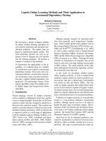
The manufacturing process, from the lignin/CNF suspensions to the
final carbon aerogels, is schematically shown in Fig. 1a, and represen
tative images of the lignin/CNF precursor and carbon aerogel are
demonstrated in Fig. 1b and c, respectively. A commercial kraft lignin
from traditional kraft pulping process was first used to determine the
optimized lignin/CNF ratio, suspension solid content, and carbonization
time, as shown in Table 1. Another type of lignin generated from the
2.2. Physical and thermal properties of carbon aerogels and their raw
materials
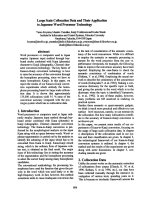
The viscosity of the lignin/CNF suspensions, as shown in Fig. 2a,
varied significantly with the lignin/CNF ratio, solid content, and lignin
type. The K75/25-3w and K85/15-6w suspensions had viscosities of 96
and 91 mPa s, respectively, which were much higher than those of K85/
15-3w (26 mPa s), due to the higher CNF content (25 wt% vs. 15 wt% of
dry weight) and solid content (6 wt% vs. 3 wt%). Compared to the K85/
15-3w, the L85/15-3w suspension interestingly showed a lower viscos
ity of 11 mPa s likely due to both the difference in the charge content
between the lignoboost lignin and the kraft lignin and the different
number of hydrophilic groups in them [41]. It is obvious from Fig. 1b
and c that the lignin/CNF precursors contracted drastically during the
carbonization, and the material yield and volume shrinkage were in the
range of 33%–37% and 61%–68%, respectively, as illustrated in Fig. 2b
and Table S1. Among the carbon aerogels derived from the kraft lignin,
K85/15-6w-1h had the highest yield (37%) and the lowest volume
shrinkage (61%), caused by the higher solid content, while there was no
considerable difference between the K85/15-3w carbon aerogels with
various carbonization times at 1200 ◦ C (1, 2, and 3 h). The carbon
aerogel derived from lignoboost lignin (L85/15-3w-1h) also showed
quite high yield and low volume shrinkage, especially when compared
to K85/15-3w-1h, which had the same material composition and pro
cessing condition except the lignin type. Fig. 2c reveals that the porosity
of all carbon aerogels (calculated using Eq. (1)) reached approximately
98%, indicating the super lightweight nature of the carbon aerogels,
which is attributed to the ice-templating induced tracheid-like
macropores.
Fig. 1. (a) Schematic preparation processing from lignin/CNF aqueous sus
pensions to carbon aerogels, and representative illustrations of (b) a lignin/CNF
precursor and (c) a carbon aerogel.
2
S. Geng et al.
Microporous and Mesoporous Materials 323 (2021) 111236
Fig. 2. (a) Viscosity of the lignin/CNF suspensions. (b) Yield and volume shrinkage of the carbon aerogels from their lignin/CNF precursors and (c) porosity of the
carbon aerogels (solid columns: K85/15-3w samples with different carbonization time, columns with patterns: other samples).
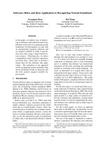
To individually understand the behaviors of the kraft lignin, the
lignoboost lignin, and the CNFs during the carbonization process, their
thermal degradation features were characterized by thermogravimetric
analysis (TGA), as shown in Fig. 3a and b. Both types of lignin experi
enced a small weight loss in the starting stage up to 100 ◦ C due to
moisture evaporation, and their primary degradation occurred at
250–450 ◦ C caused by the release of volatiles including aromatics, al
kyls, carbonyls, CO, and CO2 [42,43]. It is obvious from the derivative
thermogravimetry (DTG) curves that the kraft lignin reached the highest
rate of weight loss at a lower temperature (310 ◦ C) than the lignoboost
lignin (380 ◦ C), while the weight loss of the lignoboost lignin was much
higher than that of the kraft lignin at the primary degradation stage. The
lignoboost lignin also showed better thermal stability at higher tem
perature, as its weight loss rate gradually declined with increasing
temperature and was close to 0 after 730 ◦ C, while the weight of the kraft
lignin continued to decrease. This can be related to the higher yield of
the lignoboost lignin-derived carbon aerogel after carbonization at
1200 ◦ C (Fig. 2b). The possible reason is that the larger quantity of
phenolic hydroxyl, enol ether, and stilbene structures present in the
lignoboost lignin could trigger more crosslinking reactions at high
temperatures compared to the kraft lignin [44,45], which resulted in a
more stable carbon structure. As a comparison, the CNFs started to
degrade from 200 ◦ C, attributed to their thermally unstable
anhydro-glucuronic acid units [46], which led to a lower residue content
of 23% at 900 ◦ C than that of the kraft lignin (44%) and lignoboost lignin
(35%). This indicates that the CNFs not only contributed to the shape
stability of the lignin/CNF precursors, due to their fiber geometry with a
large aspect ratio, but also acted as sacrificial templates for generating
cavities during carbonization, which resulted in a hierarchical porous
structure in the materials. The thermal degradation behaviors of
K85/15-3w and L85/15-3w precursors were also characterized to
further compare the effects of the different types of lignin, and their TGA
curves are exhibited in Fig. S1. Due to the presence of the TOCNFs, both
precursors had the primary degradation stage at a lower temperature
region (200–400 ◦ C) with two main DTG peaks compared to that of the
neat kraft lignin and lignoboost lignin (250–450 ◦ C). K85/15-3w pre
cursor showed the highest rate of weight loss at a lower temperature
than that of L85/15-3w precursor, which corresponds to the DTG curves
of the neat lignin (Fig. 3a). In addition, it can be noticed that the TGA
residue content of L85/15-3w precursor at 900 ◦ C (32.2%) was even
lower than the yield of the L85/15-3w-1h carbon aerogel carbonized at
1200 ◦ C (37.4%, Fig. 2b). The possible reasons include that the
isothermal step at 500 ◦ C during the carbonization process increased the
thermal stability of the precursor owing to the lignin crosslinking effect,
and some volatiles and tars generated during carbonization could not be
removed as efficient as in the TGA test caused by the much bulkier
sample size. The carbon structure of the carbon aerogels was analyzed
by Raman spectroscopy, and the results are shown in Fig. 3c and Fig. S2.
All samples exhibited typical D (~1338 cm− 1) and G (~1584 cm− 1)
bands of carbon materials, which are usually assigned to the breathing
mode of disordered carbon atoms and the in-plane bond-stretching of
carbon sp2 sites, respectively. Farrari et al. interpreted that in the case of
amorphous carbon with nanocrystalline graphite, the intensity of D
band is proportional to the graphitic cluster area, which is instead
related to ordering [47]. The inset of Fig. 3c clearly demonstrates that
both K85/15-3w-2h and K85/15-3w-3h exhibited higher D-band in
tensity compared to K85/15-3w-1h, indicating that the size of graphite
crystallites in the carbon aerogels was increased by extending the
carbonization time to 2 h, while it remained constant when the time was
extended to 3 h.
2.3. Morphology and pore structure of carbon aerogels
The morphology of both the cross section and the longitudinal sec
tion (Fig. S3) of the carbon aerogels was investigated using scanning
electron microscopy (SEM), as illustrated in Fig. 4. All carbon aerogels
Fig. 3. TGA curves of (a) kraft lignin and lignoboost lignin as well as (b) 2,2,6,6-tetramethylpiperidinyl-1-oxyl radical (TEMPO)-oxidized cellulose nanofibers
(TOCNFs), and (c) Raman spectra of K85/15-3w carbon aerogels with different carbonization time (the intensity was normalized according to that of G bands).
3
S. Geng et al.
Microporous and Mesoporous Materials 323 (2021) 111236
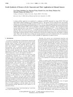
Fig. 4. SEM images of (a) K75/15-3w-1h, K85/15-3w-1h and K85/15-6w-1h (up: cross section, bottom: longitudinal section; scale bar: 50 μm), (b) K85/15-3w
carbon aerogels with different carbonization time (cross section; scale bar: 50 μm), and (c) carbon aerogels derived from different types of lignin (up: cross sec
tion, bottom: longitudinal section; scale bar: 20 μm).
exhibited an anisotropic structure with longitudinal macropores because
of the ice-templating technique, and Figs. S4 and S5 confirm that this
unique structure remained homogenous at a relatively large scale (more
than 1 mm2 in cross section). Compared to K85/15-3w-1h, K75/25-3w1h, and K85/15-6w-1h showed macropores with a more regular shape
and less wrinkled cell walls (Fig. 4a), especially in the case of the former.
This can be associated with the higher CNF concentration and solid
content in the starting lignin/CNF suspensions, which induced the for
mation of a more rigid cell structure after ice-templating and carbon
ization. There was no distinct difference between the morphology of the
carbon aerogels with different carbonization times, as shown in Fig. 4b.
For the carbon aerogels with different types of lignin (Fig. 4c), it is
interesting that the aerogel with the lignoboost lignin (L85/15-3w-1h)
also demonstrated less wrinkled and smoother cell walls, which could be
attributed to the better thermal stability of the lignoboost lignin in the
high-temperature range, corresponding to the above-mentioned yield/
volume shrinkage and TGA results.
Inspired by our earlier work [28], all carbon aerogels obtained in this
study were washed with distilled water after carbonization to remove
possible residual impurities and subsequently increase their porosity
and surface area, which acted as key factors in CO2 adsorption. To
confirm the effects of washing, Brunauer− Emmett− Teller (BET) surface
area analysis and energy-dispersive X-ray spectroscopy (SEM-EDX) were
carried out for both unwashed and washed samples, and the results are
shown in Fig. 5, Table 2, and Table S2. The N2 adsorption isotherms for
the BET analysis are shown in Figs. S6 and S7. All washed samples
demonstrated a much higher surface area compared to the unwashed
ones (Fig. 5), and one possible reason is the removal of salt compounds
that expose the previously blocked pores. This can be verified by the
EDX data shown in Table 2, where the oxygen, sodium, and potassium
contents in the kraft lignin-derived samples decreased considerably after
washing, while the relative carbon contents increased. However, the
lignoboost lignin-derived carbon aerogel (L85/15-3w-1h) did not show
a similar tendency, and the carbon content remained same, while the
oxygen content was slightly increased by washing. This indicates that
removing salts was not the only reason of the increased surface area, but
the removal of some tars generated during carbonization could also have
contributed. K85/15-3w-1h showed a higher surface area than that of
K75/25-3w-1h and K85/15-6w-1h, owing to its more accessible micro
pores (563 m2 g− 1 of micropore-surface area after washing compared to
290 and 185 m2 g− 1, respectively; Table S2), which is probably caused
by the different cell wall structure (Fig. 4a), inducing different heat
Fig. 5. BET surface area and pore size of all carbon aerogels before and after
washing (solid columns: K85/15-3w samples with different carbonization time,
columns with patterns: other samples).
transfer and carbonization effects [48]. Moreover, it was obvious that
increasing carbonization time from 1 h to 2 h significantly reduced the
surface area of the carbon aerogels and slightly increased the average
pore size (from 1.6 to 1.9 nm, after washing). This was likely because
more severe migration of carbon atoms resulted in pore merging in the
samples with a longer carbonization time at 1200 ◦ C [49].
2.4. Adsorption properties of carbon aerogels
The CO2 adsorption isotherms of all the washed carbon aerogels were
measured in the 0–120 kPa pressure range and at three different tem
peratures, which were 273, 298, and 323 K. Fig. 6a and b reveal that
L85/15-3w-1h surprisingly exhibited a superior CO2 adsorption capacity
compared to K85/15-3w-1h at all temperatures, which at 273 K reached
1.94 and 6.28 mmol g− 1 at 10 and 100 kPa, respectively. This was not in
agreement with the BET surface area results (Fig. 5), in which L85/153w-1h showed a drastically lower surface area (380 m2 g− 1 compared
to 643 m2 g− 1). This phenomenon implied that a large number of ultramicropores could be present in L85/15-3w-1h, which were accessible for
CO2 while not detectable in BET measurements using N2 at 77 K because
4
S. Geng et al.
Microporous and Mesoporous Materials 323 (2021) 111236
Table 2
Elemental composition (in at. %) of the carbon aerogels before and after washing according to the SEM-EDX.
Sample coding
K75/25-3w-1h
K85/15-3w-1h
K85/15-6w-1h
K85/15-3w-2h
K85/15-3w-3h
L85/15-3w-1h
Unwashed
Washed
C
O
Na
Si
S
K
C
O
Na
Si
S
K
95.8
94.5
94.7
97.7
97.9
97.6
3.1
3.8
4.0
1.7
1.7
1.6
0.5
–
0.8
0.1
0.1
0.4
0.1
–
–
–
–
–
0.4
0.4
0.4
0.3
0.2
0.4
0.1
1.3
0.1
0.2
0.1
–
98.0
97.8
97.1
98.2
98.4
97.4
1.4
1.9
2.2
1.4
1.3
2.2
0.1
–
0.3
–
–
0.1
0.1
–
–
–
–
–
0.4
0.2
0.4
0.3
0.3
0.3
–
0.1
–
0.1
–
–
Fig. 6. (a,b) CO2 adsorption isotherms with Langmuir model-fitting curves of K85/15-3w-1h and L85/15-3w-1h at 273, 298 and 323 K; and (c,d) the quantity of
adsorbed CO2 at the pressures of 10 and 100 kPa of all prepared carbon aerogels at the various temperatures used (i: K85/15-6w-1h, ii: L85/15-3w-1h, ii: K85/15-3w2h, iv: K85/15-3w-3h, v: K75/25-3w-1h, vi: K85/15-3w-1h).
of the smaller quadrupole moment and more diffusional restrictions of
N2 when compared to CO2 [17,50,51]. The data of CO2 adsorption ca
pacity of all samples as a function of BET surface area are summarized in
Fig. 6c and d and Table S3. Among the kraft lignin-derived carbon
aerogels, K85/15-3w-1h possessed the largest surface area and showed
the highest CO2 adsorption capacity at 10 kPa, because of its large
quantity of accessible micropores (Table S2). However, at 100 kPa, a
similar CO2 adsorption capacity was observed for all kraft lignin-based
samples, except for K85/15-6w-1h, which had a much smaller surface
area. To further investigate this, Fig. S8 compares the CO2 adsorption
isotherms recorded at 273 K of the K85/15-3w carbon aerogels with
different carbonization times. With increasing carbonization time, the
isotherm slope in the relatively high-pressure range increased positively,
and the adsorption quantity of K85/15-3w-3h exceeded that of both
K85/15-3w-1h and K85/15-3w-2h at pressures higher than 85 kPa. This
was likely due to the larger pore size of the samples with longer
carbonization times (Table S2), resulting in the condensation of CO2
molecules in the pores at high pressure. A similar behavior, that of a
steep isotherm slope at high pressure, was also observed for
K75/25-3w-1h (Fig. S9), which had a pore size of 2.1 nm. In addition, by
calculating the CO2 adsorption enthalpy (ΔH) and entropy (ΔS) of the
samples from their isotherms at various temperatures (Eq. (2) and Eq.
(3)), it can be seen in Fig. 7 that the absolute values of ΔH (|ΔH|) of
K75/15-3w-1h, K85/15-3w-2h, and K85/15-3w-3h are greater than the
other two kraft lignin-based samples, which illustrates that they can
provide stronger affinity for CO2. L85/15-3w-1h exhibited a relatively
low affinity for CO2 (|ΔH| is 19.98 kJ mol− 1), while still showed
promising CO2 adsorption capacity, even when compared to many
literature-reported carbonaceous adsorbents prepared with various
activation processes (Table 3), revealing its excellence not only in CO2
capture but also in adsorbent regeneration.
As L85/15-3w-1h outperformed all the other samples, showing the
highest CO2 adsorption capacity, it was selected to evaluate the CO2/N2
selectivity and water vapor adsorption, as well as the monolithic prop
erties, including the column breakthrough adsorption capacity and
mechanical properties. Fig. 8a shows the comparison between the CO2
and N2 adsorption isotherms of L85/15-3w-1h at 298 K. The CO2/N2
selectivity was estimated to be 21 from the ratio of the slope of the
5
S. Geng et al.
Microporous and Mesoporous Materials 323 (2021) 111236
the typical water vapor adsorption behavior of hydrophobic carbon
materials with a hierarchical porous structure [56,57]. The adsorption
capacity of L85/15-3w-1h was recorded as 0.46 mmol g− 1 at a pressure
of 1 kPa, which is considerably lower than that of bituminous coal-based
activated carbons at the same temperature (approximately 1–2 mmol
g− 1 at 298 K) [58,59]. This is probably because the high carbonization
temperature (1200 ◦ C) used for the carbon aerogels led to a more hy
drophobic surface with fewer sorption sites for water molecules.
Fig. 8c illustrates the results from the forward-step change break
through experiment for the L85/15-3w-1h with a 10 kPa CO2/90 kPa N2
mixture, which was used to simulate the realistic conditions of postcombustion capture. The test setup is depicted in Fig. S11, where
several carbon aerogels were loaded in the column to achieve a suffi
cient ratio of adsorbent length to diameter. By integrating the area be
tween the sample curve and the curve of the empty column, a dynamic
CO2 adsorption capacity of 0.67 mmol g− 1 was obtained. The value was
lower than that obtained from the equilibrium measurement at the same
pressure and temperature (1.11 mmol g− 1 at 10 kPa CO2 and 298 K)
because of the competitive adsorption from N2. According to the abovementioned CO2/N2 selectivity of L85/15-3w-1h (a value of 21), its
theoretical CO2 adsorption capacity under a 10 kPa CO2/90 kPa N2 at
mosphere can be calculated as 0.63 mmol g− 1, which corresponds very
well with the measured result.
Fig. 7. Enthalpy (ΔH) and entropy (ΔS) of CO2 adsorption of all carbon aerogels
(solid columns: K85/15-3w samples with different carbonization time, columns
with patterns: other samples).
Table 3
Comparison of CO2 adsorption capacity at 100 kPa and 298 K between L85/153w-1h and other carbonaceous adsorbents made from various precursors pre
pared by different processes, as reported in literature.
2.5. Mechanical properties of monolithic carbon aerogels
Material
code
Carbon
resource
Processing
CO2
adsorption
capacity
(mmol g− 1)
Reference
CP-2-600
Polypyrrole
3.84
[21]
MFB-600
2.25
[31]
GKOSA50
Melamine and
formaldehyde
Olive stones
Nitrogen-doping
and chemical
activation
Pyrolysis
2.43
[32]
AA750
Almond shell
2.66
[33]
HCMDAH-1900-1
Resorcinol and
formaldehyde
3.30
[34]
3. Conclusions
AS-2-600
Sawdust
NCP-800
Coal tar pitch
Y–K-600
Yeast
L85/153w-1h
Lignoboost
lignin and
nanocellulose
Pyrolysis and
physical
activation
Pyrolysis and
physical
activation
Nitrogen-doping,
pyrolysis, and
physical
activation
Hydrothermal
carbonization and
chemical
activation
Nitration and
pyrolysis
Pyrolysis and
chemical
activation
Pyrolysis
The mechanical properties of L85/15-3w-1h in both the axial and
radial directions were characterized by compression testing, and the
acquired stress-strain curves are shown in Fig. 9. The sample exhibited
distinct anisotropic mechanical behaviors, which was attributed to the
ice-templating induced tracheid-like porous structure. The elastic
modulus of the sample in the axial direction was as high as 2.64 MPa
(Table S4) with a specific elastic modulus of 61.2 kNm kg− 1 (calculated
using Eq. (4)), while in radial direction the sample showed good flexi
bility, reaching 50% of the strain before collapse. The excellent me
chanical properties of the carbon aerogels with a porosity as high as 98%
make them a viable choice for CO2 capture applications without any
supporting materials or binders, demonstrating their potential as inde
pendent CO2 adsorbents in the future.
4.82
[35]
2.20
[36]
4.77
[37]
4.49
This work
In summary, we have demonstrated that carbon aerogels based on
lignin and CNFs with anisotropic, hierarchical porous structures were
successfully prepared via a straightforward procedure combining icetemplating and carbonization. By tailoring the CNF concentration,
solid content, and carbonization time, the structure of the carbon aer
ogels, including the carbon structure, morphology, porous structure, and
surface area, were varied, which consequently led to different CO2
adsorption capabilities. The different lignin structure generated from
different types of lignin affected their thermal degradation behaviors
during carbonization, also resulting in significant variations in the
structure and properties of the obtained carbon aerogels. The carbon
aerogel containing lignoboost lignin reached a CO2 adsorption capacity
of 4.49 mmol g− 1 at 298 K and 100 kPa, which is competitive among
previously reported carbon-based adsorbents, while possessing a good
CO2/N2 selectivity of 21 and a low water vapor adsorption capacity up
to 1.5 kPa of vapor pressure. Furthermore, we have also discovered that
carbon aerogels had excellent mechanical properties and could be used
alone in a column for CO2 capture without the need for any additional
binders, which is expected to initiate the further development of
monolithic carbonaceous CO2 adsorbents with large adsorption capac
ity, high selectivity, fast adsorption-desorption kinetics, and easy
regeneration.
isotherm linear regions in the low pressure range (≤10 kPa), which is
higher than or comparable to that of many modified carbon materials
[22,52,53]. The water vapor adsorption of the sample was evaluated at
298 K in the 0–3.169 kPa pressure range (up to the saturated vapor
pressure) [54]. The isotherm is shown in Fig. 8b and can be described as
a Type-V isotherm according to the IUPAC classification [55]. This in
dicates that the amount of adsorbed water was relatively low at pres
sures below 1.5 kPa, while significant capillary condensation of water
molecules occurred at higher pressures. Finally, the sample reached a
high-water adsorption capacity due to pore filling. This corresponds to
6
S. Geng et al.
Microporous and Mesoporous Materials 323 (2021) 111236
Fig. 8. (a) CO2 and N2 adsorption isotherms of L85/15-3w-1h at 298 K, and (b) water vapor adsorption isotherm and (c) forward-step change breakthrough curves
with CO2/N2 mixture (volume ratio of 10/90) of L85/15-3w-1h and the empty column at 298 K.
4.3. Preparation of carbon aerogels
The carbon aerogels were prepared by the carbonization of the
lignin/CNF precursors under a nitrogen atmosphere using a tube furnace
(RHTC-230/15, Nabertherm GmbH, Lilienthal, Germany). The heating
procedure included temperature ramp from room temperature to 100 ◦ C
with an isothermal holding time of 2 h, ramp from 100 to 500 ◦ C and
holding for 100 min, and a final ramp up to 1200 ◦ C with different
holding times of 1, 2, and 3 h. The heating rate of all ramp steps was
5 ◦ C/min. Then, the carbonized samples were washed with distilled
water five times at 30-min intervals and dried in an oven at 80 ◦ C
overnight to obtain the final carbon aerogels.
4.4. Characterizations
The viscosity of the lignin/CNF suspensions was measured using an
SV-10 Vibro viscometer (A&D Company, Tokyo, Japan) at 22 ◦ C. TGA
was performed using a TA Q500 thermogravimetric analyzer (TA In
struments, New Castle, DE, USA) under a nitrogen atmosphere, with a
temperature range from room temperature to 900 ◦ C and a heating rate
of 10 ◦ C/min. The porosity of the carbon aerogels was calculated as
follows:
(
)
ρ∗
P= 1−
× 100%
Eq. 1
Fig. 9. Representative stress-strain curves of L85/15-3w-1h from compression
testing in both axial and radial directions.
4. Material and methods
4.1. Materials
ρ
Kraft lignin with a low sulfonate content (Mw of ~10,000) was
purchased from Sigma-Aldrich, Sweden AB. Lignoboost lignin was
supplied by Domtar Plymouth pulp mill (NC, USA) with a Mw of 6772
and a purity of 96.5% [40]. Cellulose nanofibers (CNFs) were prepared
through 2,2,6,6-tetramethylpiperidinyl-1-oxyl radical (TEMPO)-me
diated oxidation treatment followed by a homogenization process, as
described in our previous study [28]. Sodium hydroxide (NaOH, pure
pellets) was purchased from Merck KGaA, Germany. All chemicals were
used as received.
where ρ and ρ* denote the density of the solid carbon (2.1 g cm− 3) [54]
and the bulk density of the carbon aerogels, respectively. The carbon
structure was characterized by Raman spectroscopy using a Bruker
Senterra dispersive Raman spectroscope (Bruker Corp., Billerica, MA,
USA) with a 533 nm laser beam. SEM was conducted using a JEOL JSM
6460 L V scanning electron microscope (JEOL Ltd., Tokyo, Japan). The
elemental composition of the samples was examined by SEM-EDX
equipped with a silicon drift detector (Oxford X-MaxN 50 mm2, Ox
ford Instruments, Oxfordshire, UK). BET surface area analysis was car
ried out according to N2 adsorption tests at 77 K using a Gemini VII
2390a analyzer (Micromeritics Instrument Corp., Norcross, GA, USA).
The samples were degassed at 300 ◦ C for 4 h prior to the tests. CO2
adsorption measurements were performed with an ASAP 2020 Plus BET
analyzer (Micromeritics Instrument Corp., Norcross, GA, USA). The
pressure ramp was from 0 to 120 kPa at 273, 298, and 323 K, respec
tively, after the degas step. Based on the adsorption isotherm data at low
pressure (<20 kPa), the enthalpy (ΔH) and entropy (ΔS) of the CO2
adsorption of each sample were calculated using the Langmuir adsorp
tion model and van’t Hoff equation:
4.2. Preparation of lignin/CNF precursors
Kraft lignin/CNF suspensions with various lignin to CNF ratios and
different solid contents were obtained by directly mixing kraft lignin,
the CNF suspension (1 wt%), and distilled water at room temperature for
2 h. To prepare the lignoboost lignin/CNF suspension, the lignin was
first dissolved in a NaOH solution, where the amount of NaOH was 14 wt
% of the lignin dry weight, and then the lignin solution was stirred
together with the CNF suspension. Afterwards, both types of lignin/CNF
suspensions were ice-templated unidirectionally at a freezing rate of 10
K/min to form an anisotropic structure. The ice-templating setup is
described in detail in our earlier work [28]. The frozen samples were
then freeze-dried using an Alpha 2–4 LD plus freeze-dryer (Martin Christ
GmbH, Germany) to generate porous lignin/CNF precursors.
1
1
1
) +
=(
qe
Keq Qm Ce Qm
Eq. 2
ΔH ΔS
+
RT
R
Eq. 3
ln Keq = −
7
Microporous and Mesoporous Materials 323 (2021) 111236
S. Geng et al.
[4] C. Gouedard, D. Picq, F. Launay, P.-L. Carrette, International Journal of
Greenhouse Gas Control 10 (2012) 244–270, />ijggc.2012.06.015.
[5] T. Inui, Y. Okugawa, M. Yasuda, Ind. Eng. Chem. Res. 27 (7) (1988) 1103–1109,
/>[6] T. Yamazaki, M. Katoh, S. Ozawa, Y. Ogino, Mol. Phys. 80 (2) (1993) 313–324,
/>[7] E.S. Kikkinides, R. Yang, S. Cho, Ind. Eng. Chem. Res. 32 (11) (1993) 2714–2720,
/>[8] K. Chue, J. Kim, Y. Yoo, S. Cho, R. Yang, Ind. Eng. Chem. Res. 34 (2) (1995)
591–598, />[9] S. Choi, J.H. Drese, C.W. Jones, ChemSusChem 2 (9) (2009) 796–854, https://doi.
org/10.1002/cssc.200900036.
[10] J. An, N.L. Rosi, J. Appl. Comput. Sci. 132 (16) (2010) 5578–5579, https://doi.
org/10.1021/ja1012992.
[11] T.-L. Chew, A.L. Ahmad, S. Bhatia, Adv. Colloid Interface Sci. 153 (1–2) (2010)
43–57, />[12] N.P. Wickramaratne, M. Jaroniec, Mater Acs Appl, Interfaces 5 (5) (2013)
1849–1855, />[13] C. Chen, B. Li, L. Zhou, Z. Xia, N. Feng, J. Ding, L. Wang, H. Wan, G. Guan,
Mater Acs Appl, Interfaces 9 (27) (2017) 23060–23071, />acsami.7b08117.
[14] A. Vidoni, P.I. Ravikovitch, M. Afeworki, D. Calabro, H. Deckman, D. Ruthven,
Microporous Mesoporous Mater. 294 (2020) 109818, />micromeso.2019.109818.
[15] S. Ullah, M.A. Bustam, A.G. Al-Sehemi, M.A. Assiri, F.A.A. Kareem, A. Mukhtar,
M. Ayoub, G. Gonfa, Microporous Mesoporous Mater. 296 (2020) 110002, https://
doi.org/10.1016/j.micromeso.2020.110002.
[16] S. Sircar, T. Golden, M. Rao, Carbon 34 (1) (1996) 1–12, />0008-6223(95)00128-X.
[17] H. Marsh, F.R. Reinoso, Characterization of Activated Carbon, Activated Carbon,
Elsevier, 2006, pp. 143–242.
[18] A. Wahby, J.M. Ramos-Fern´
andez, M. Martínez-Escandell, A. Sepúlveda-Escribano,
J. Silvestre-Albero, F. Rodríguez-Reinoso, ChemSusChem 3 (8) (2010) 974–981,
/>[19] W. Qiu, F.S. Li, S. Fu, W.J. Koros, ChemSusChem 13 (19) (2020) 5318–5328,
/>[20] G.P. Hao, W.C. Li, D. Qian, A.H. Lu, Adv. Mater. 22 (7) (2010) 853–857, https://
doi.org/10.1002/adma.200903765.
[21] M. Sevilla, P. Valle-Vig´
on, A.B. Fuertes, Adv. Funct. Mater. 21 (14) (2011)
2781–2787, />[22] J.W. To, J. He, J. Mei, R. Haghpanah, Z. Chen, T. Kurosawa, S. Chen, W.-G. Bae,
L. Pan, J.B.-H. Tok, J. Appl. Comput. Sci. 138 (3) (2016) 1001–1009, https://doi.
org/10.1021/jacs.5b11955.
[23] Z. Ma, Z. Yang, H. Zhang, Z. Liu, Microporous Mesoporous Mater. 296 (2020)
109992, />[24] D.J. Babu, M. Lange, G. Cherkashinin, A. Issanin, R. Staudt, J.J. Schneider, Carbon
61 (2013) 616–623, />[25] Y. Jin, S.C. Hawkins, C.P. Huynh, S. Su, Energy Environ. Sci. 6 (9) (2013)
2591–2596, />[26] D.J. Babu, M. Bruns, R. Schneider, D. Gerthsen, J.r.J. Schneider, J. Phys. Chem. C
121 (1) (2017) 616–626, />[27] A. Mukhtar, N. Mellon, S. Saqib, A. Khawar, S. Rafiq, S. Ullah, A.G. Al-Sehemi,
M. Babar, M.A. Bustam, W.A. Khan, Microporous Mesoporous Mater. 294 (2020)
109883, />[28] S. Geng, J. Wei, S. Jonasson, J. Hedlund, K. Oksman, Mater Acs Appl, Interfaces 12
(6) (2020) 7432–7441, />[29] M. Norgren, H. Edlund, Curr. Opin. Colloid Interface Sci. 19 (5) (2014) 409–416,
/>[30] M. Jonoobi, A.P. Mathew, K. Oksman, Natural Resources and Residues for
Production of Bionanomaterials, Handbook of Green Materials: 1
Bionanomaterials: Separation Processes, Characterization and Properties, World
Scientific, 2014, pp. 19–33.
[31] C. Pevida, T. Drage, C. Snape, Carbon 46 (11) (2008) 1464–1474, />10.1016/j.carbon.2008.06.026.
[32] M. Plaza, C. Pevida, B. Arias, J. Fermoso, M. Casal, C. Martín, F. Rubiera, J. Pis,
Fuel 88 (12) (2009) 2442–2447, />[33] M. Plaza, C. Pevida, C.F. Martín, J. Fermoso, J. Pis, F. Rubiera, Separ. Purif.
Technol. 71 (1) (2010) 102–106, />[34] G.-P. Hao, W.-C. Li, D. Qian, G.-H. Wang, W.-P. Zhang, T. Zhang, A.-Q. Wang,
F. Schüth, H.-J. Bongard, A.-H. Lu, J. Appl. Comput. Sci. 133 (29) (2011)
11378–11388, />[35] M. Sevilla, A.B. Fuertes, Energy Environ. Sci. 4 (5) (2011) 1765–1771, https://doi.
org/10.1039/C0EE00784F.
´ Lillo-R´
[36] J. Alca˜
niz-Monge, J.P. Marco-Lozar, M.A.
odenas, Fuel Process. Technol. 92
(5) (2011) 915–919, />[37] W. Shen, Y. He, S. Zhang, J. Li, W. Fan, ChemSusChem 5 (7) (2012) 1274–1279,
/>[38] Z. Chen, S. Deng, H. Wei, B. Wang, J. Huang, G. Yu, Front. Environ. Sci. Eng. 7 (3)
(2013) 326–340, />[39] P. Tomani, Cellul. Chem. Technol. 44 (1) (2010) 53.
[40] Z. Hu, X. Du, J. Liu, H.-m. Chang, H. Jameel, J. Wood Chem. Technol. 36 (6)
(2016) 432–446, />[41] M. Kosa, H. Ben, H. Theliander, A.J. Ragauskas, Green Chem. 13 (11) (2011)
3196–3202, />
where Ce and qe represent the pressure and the amount of adsorbed CO2
at equilibrium, respectively, Keq denotes the equilibrium constant, Qm is
related to the maximum capacity of the adsorbent, T is the temperature,
and R is the Avogadro constant. N2 and water vapor adsorption iso
therms at 298 K were also collected from the ASAP 2020 Plus BET
analyzer. Breakthrough experiment was performed at room temperature
in the setup shown in Fig. S11. The diameter of the adsorption column
was 20 mm. To eliminate the gap between the carbon aerogels and
column, the carbon aerogels were surrounded by Teflon tape and packed
in the column. The bulk volume of the carbon aerogels was 44 mL.
Before the experiment, the carbon aerogels were dried at 100 ◦ C over
night under a flow of N2. A digital mass flow controller (Bronkhorst, HITEC, Netherlands) was used to feed the CO2/N2 gas mixture (10%/90%
by volume) to the column at a flow rate of 65 ml/min. The CO2 con
centration at the outlet of the column was measured using an online
carbon dioxide analyzer (CA-10, Sable Systems International, North Las
Vegas, NV, USA). A blank experiment was conducted with an empty
column. Compression testing was conducted using a TA Q800 dynamic
mechanical analyzer (TA Instruments, New Castle, DE, USA). At least
four specimens were cut into cubes with an edge length of approxi
mately 1 cm and tested at 30 ◦ C with a strain rate of − 5% min− 1 in both
the axial and radial directions (parallel and perpendicular to the freezing
direction of ice templating, respectively). Average values of elastic
modulus (E) and yield strength were calculated, and the specific elastic
modulus (Es) of the aerogel was determined as follows:
Es =
E
ρ*
Eq. 4
CRediT authorship contribution statement
Shiyu Geng: Conceptualization, Methodology, Investigation, Su
pervision, Data curation, Formal analysis, Visualization, Writing –
original draft, Writing – review & editing. Alexis Maennlein: Investi
gation, Validation. Liang Yu: Investigation, Validation, Formal analysis,
Writing – review & editing. Jonas Hedlund: Funding acquisition, Re
sources, Supervision, Writing – review & editing. Kristiina Oksman:
Funding acquisition, Project administration, Resources, Supervision,
Writing – review & editing.
Declaration of competing interest
The authors declare that they have no known competing financial
interests or personal relationships that could have appeared to influence
the work reported in this paper.
Acknowledgment
This work was financially supported by Swedish Strategic Research
Program Bio4Energy. Maria Harila is acknowledged for sample prepa
ration for the breakthrough test. Prof. Mohini Sain is thanked for kindly
providing the lignoboost lignin.
Appendix A. Supplementary data
Supplementary data to this article can be found online at https://doi.
org/10.1016/j.micromeso.2021.111236.
References
[1] D.W. Keith, Science 325 (5948) (2009) 1654–1655, />science.1175680.
[2] S. Rasi, A. Veijanen, J. Rintala, Energy 32 (8) (2007) 1375–1380, />10.1016/j.energy.2006.10.018.
[3] G.F. Versteeg, L.A.J. Van Dijck, W.P.M. van Swaaij, Chem. Eng. Commun. 144 (1)
(1996) 113–158, />
8
S. Geng et al.
Microporous and Mesoporous Materials 323 (2021) 111236
[51] J.C. Groen, L.A. Peffer, J. P´erez-Ramı ́rez, Microporous Mesoporous Mater. 60 (1–3)
(2003) 1–17, />[52] S.M. Mahurin, J. G´
orka, K.M. Nelson, R.T. Mayes, S. Dai, Carbon 67 (2014)
457–464, />[53] A. Modak, A. Bhaumik, J. Solid State Chem. 232 (2015) 157–162, />10.1016/j.jssc.2015.09.022.
[54] D.R. Lide, CRC Handbook of Chemistry and Physics, CRC press, 2004.
[55] K.S. Sing, Pure Appl. Chem. 57 (4) (1985) 603–619, />pac198557040603.
[56] M. Dubinin, Carbon 18 (5) (1980) 355–364, />(80)90007-X.
[57] D. Do, H. Do, Carbon 38 (5) (2000) 767–773, 00159–1.
[58] S. Barton, M. Evans, J. Holland, J. Koresh, Carbon 22 (3) (1984) 265–272, https://
doi.org/10.1016/0008-6223(84), 90170–90172.
[59] E.N. Rudisill, J.J. Hacskaylo, M.D. Levan, Ind. Eng. Chem. Res. 31 (4) (1992)
1122–1130, />
[42] Z. Ma, Q. Sun, J. Ye, Q. Yao, C. Zhao, J. Anal, Appl. Pyrolysis 117 (2016) 116–124,
/>[43] M. Zhang, F.L. Resende, A. Moutsoglou, D.E. Raynie, J. Anal, Appl. Pyrolysis 98
(2012) 65–71, />[44] M.A. Serio, S. Charpenay, R. Bassilakis, P.R. Solomon, Biomass Bioenergy 7 (1–6)
(1994) 107–124, />[45] D. Stewart, Ind. Crop. Prod. 27 (2) (2008) 202–207, />indcrop.2007.07.008.
[46] H. Fukuzumi, T. Saito, Y. Okita, A. Isogai, Polym. Degrad. Stabil. 95 (9) (2010)
1502–1508, />[47] A.C. Ferrari, J. Robertson, Phys. Rev. B 61 (20) (2000) 14095, />10.1103/PhysRevB.61.14095.
[48] A. Demirbas, J. Anal, Appl. Pyrolysis 72 (2) (2004) 243248, />10.1016/j.jaap.2004.07.003.
[49] J. Wei, S. Geng, O. Pitkă
anen, T. Jarvinen, K. Kordas, K. Oksman, ACS Appl. Energy
Mater. 3 (4) (2020) 3530–3540, />[50] F. Rodrıguez-Reinoso, M. Molina-Sabio, Adv. Colloid Interface Sci. 76 (1998)
271–294, />
9