Experimental investigation of steam condensation in water tank at subatmospheric pressure
Bạn đang xem bản rút gọn của tài liệu. Xem và tải ngay bản đầy đủ của tài liệu tại đây (4.44 MB, 14 trang )
Nuclear Engineering and Design 335 (2018) 241–254
Contents lists available at ScienceDirect
Nuclear Engineering and Design
journal homepage: www.elsevier.com/locate/nucengdes
Experimental investigation of steam condensation in water tank at subatmospheric pressure
T
⁎
D. Mazedc, R. Lo Franoa, , D. Aquaroa, D. Del Serraa, I. Sekachevb, M. Olceseb
a
Department of Civil and Industrial Engineering, University of Pisa, Italy
ITER Organization, St Paul Lez Durance Cedex, France
c
Studiecentrum voor kernenergie - Centre d'étude de l'énergie nucléaire (SCK-CEN), Boeretang 200, Mol, Belgium
b
A R T I C LE I N FO
A B S T R A C T
Keywords:
Steam condensation
Steam direct contact condensation
ITER
VVPSS
Fusion reactor technology
Tokamak technology
Nuclear safety
The International Thermonuclear Experimental Reactor (ITER) Vacuum Vessel Pressure Suppression System
(VVPSS) limits the Vacuum Vessel (VV) internal pressure, in case of loss of coolant (LOCA) or other pressurizing
accidents from the in-vessel components, to 150 kPa (abs). This is key safety function because a large internal
pressure could lead to a breach of the primary confinement barrier. Safety is ensured by discharging the steam
evolved during the accident event to the VVPSS suppression tanks where it is condensed. Steam condensation
occurs at sub-atmospheric pressure condition. Moreover, being this latter not standard for traditional nuclear
systems, this investigation is quite new (not studied in detail before) and deals with an experimental investigation of the direct contact condensation at VVPSS prototypical thermal-hydraulic conditions.
To the purpose, a small-scale experimental rig was properly designed and built at Lab. B. Guerrini of DICIUniversity of Pisa as well as different temperature, pressure and steam mass (flow rate per hole) conditions and
sparger patterns have been investigated. The experimental test matrix is also presented in this study.
The obtained results show high efficiency of condensation for all examined conditions. The main condensation regimes at sub-atmospheric pressure conditions were identified. In addition, a comparison was done
between the condensation regimes experimentally determined and those available in the literature, which were
obtained at atmospheric pressure. Finally, results demonstrated to be representative of the real configuration at
ITER reactor.
1. Introduction
The steam condensation plays an important role in a variety of high
efficient engineering systems such as heat pipes, nuclear power plants
(fission technology), seawater desalination units etc.
During the condensation, it is generally assumed that the only rate
controlling process is the heat transfer across the condensate layer.
The direct contact condensation (DCC) of steam injected into a pool
of subcooled water is a well-known (Al-Shammari, 2004; Huang, 2015;
Hong, 2012) and widely studied at atmospheric condition, involving
pure steam or steam with non-condensable gases.
At “sonic” condition, a stable cone of steam forms at the outlet, so
that it is possible to measure its length and, consequently, the surface of
separation between steam and liquid through which the heat transfer
takes place. Varying the specific mass flowrate and the subcooling, a
transition between stable and instable behaviour may take place, and
the transfer of vapour to the water surface may become controlled by
diffusion than convection.
⁎
With reference to the nuclear application, a lot of experience has
been gained studying the pressure suppression pool in BWR, although
studies on steam condensation referred also to the drain tank and the
in-containment refuelling water storage tank (IRWST) in advanced
PWRs.
By reviewing the state of art concerning mainly the steam condensation at atmospheric pressure, it emerged that the attention of
researchers was focused on the following aspects:
“Dimension” of steam plume into the water (shape and length);
Investigation of DCC and heat transfer coefficient;
Identification of condensation regime map (with condensation regime operation prevailing for a set of established parameters);
Characteristics of pressure waves generated during DCC (vibrations
investigation).
In particular, although several theoretical and experimental studies
were conducted on DCC, such as the experimental works at low steam
Corresponding author.
E-mail address: (R. Lo Frano).
/>Received 25 January 2018; Received in revised form 23 May 2018; Accepted 25 May 2018
0029-5493/ © 2018 The Author(s). Published by Elsevier B.V. This is an open access article under the CC BY-NC-ND license ( />
Nuclear Engineering and Design 335 (2018) 241–254
D. Mazed et al.
mass flux conditions of Aya and Nariai (1991), or at intermediate range
of steam mass flux of Young et al. (1974) and of Fukuda (1982), details
of the DCC phenomena are not well understood. Moreover, Cumo et al.
(1978) and Chun et al. (1996) provide correlation for a wide range of
steam mass flux conditions while Del Tin et al. (1983), Stanford and
Webster (1972) and Kerney et al. (1972), etc. proposed empirical correlation of the steam jet length for relatively low and high steam mass
flux conditions respectively, even if these latter are not in agreement
with each other.
Tsai and Kazimi (1976) and Chen and Faith (1982) studied the
steam jet penetration by proposing simple models to describe the jet
penetration distance. Unfortunately, a limit of their models is represented by the dependence of the prediction of steam jet length on
the made assumptions. Song et al. (1998) as well Kim et al. (1997)
observed that the steam jet may assume different shapes (conical, ellipsoidal and divergent) depending on the steam mass flux, the subcooling (water temperature) and the nozzle diameter. Similar considerations were provided earlier by Cumo et al. (1978). Further
outcomes on DCC are provided in Kim et al. (1997), in which it is indicated how for large water sub-cooling and low steam mass velocity,
the steam jet looks like a conical shape, while for intermediate and
large water sub-cooling the plume shape tends to be ellipsoidal.
Zhu et al. (2013) investigated DCC of stable steam jet in water flow
in a vertical pipe (for pool temperature range 20–70 °C and for single
nozzle of 8 mm diameter), while Huang et al. (2015) provided a broad
review of vapour condensation mechanisms.
As a conclusion, it has to be remarked that quite all the studies
available in literature refer to DCC at atmospheric; this makes the study
we will present in what follows new and difficult to compare with the
others.
This paper focuses on investigating experimentally the DCC of steam
at the Vacuum Vessel Pressure Suppression System (VVPSS) prototypical thermal-hydraulic conditions (i.e. sub-atmospheric condition)
and deriving prediction to be used to support its configuration design. It
is also worthy to note that the VVPSS thermal-hydraulic conditions,
characterized by slightly superheated steam condensed, at very low
(near vacuum) pressure, in water at close saturation condition, are not
standard for traditional fission nuclear power systems. This peculiarity
makes the proposed assessment new in the nuclear field: in fact, neither
experimental nor analytical investigations of DCC at sub-atmospheric
pressure are available in literature, as already indicated.
In what follows, a description of the VVPSS and a description of the
experimental apparatus built at the DICI- University of Pisa are provided in Sections 2 and 3 respectively. In Section 4 the steam DCC and
test matrix are presented, while the results are discussed in Section 5.
6.2 m and an overall height of about 4.7 m. The system is made of 3
Large Leak Tanks (LLTs) and 1 Small Leak Tank (SLT) located in the
DTR Fig. 1. The LLTs contain about 60 m3 of water each, and are supposed to manage bigger loss of coolant accident (LOCA) events (cat. III
and IV), while the SLT contains 40 m3 of water and it is supposed to
manage smaller LOCA events (cat. II).
The STs are designed to limit the final water temperature to 95 °C
(corresponding to a saturated vapour pressure of about 84.6 kPa), for
any LOCA event (Lo Frano et al., 2016). During an in-vessel coolant
leak (Ingress of Coolant Event (ICE)) the VVPSS acts together with the
VV drainage system, the former discharging evolved steam to the STs
where it is condensed, while the latter facilitates drainage of water from
the VV. In consideration of that, it can be seen that DCC into the STs
water is the thermal-hydraulic phenomenon which guarantees the VV
pressure safety limit not to be exceeded in case of VV pressure build-up.
They are filled with enough water (the total amount in normal operation is around 220 m3) at room temperature such as to condense steam
resulting from the most severe in-vessel coolant leaks, and to limit the
over-pressurization within VV to about 150 kPa absolute. STs are connected to the VV through pipeline as shown in previous Fig. 1a.
The SLT is connected by means of a DN300 relief line to one pipeline. A fully redundant set of double vacuum isolation bleed valves
DN250 is provided to allow the trapped volume evacuation and the leak
checking of the valves, as in the current VVPSS. With this design the
amount of contaminated water following a Category II ICE is very
limited. The LLTs are instead connected in parallel to DN500 relief line,
along which two sets of rupture disks, working in parallel, for full redundancy are located (to guarantee that, in case of partial opening of
one of the two sets of rupture disks, the opening pressure of the second
set is not impacted by the pressure build-up downstream of the rupture
disk assembly).
The rupture disks (main vacuum confinement boundary in normal
operation) would cope with the design and beyond design basis events:
when accident occurs, their opening will ensure the excess of steam is
released to the DTR and condensed in STs. The system also can be used
also to provide over pressure protection and to enhance confinement,
maintaining thus continuously low pressure in the VV system. Fig. 2
shows the two different relief lines connecting the VV to the LLTs and
SLT.
As shown in Fig. 2, the two relief lines (DN300 and DN500) are fully
independent and are provided by redundant valves, whose opening
occurs automatically when the pressure in VV overpasses 92 kPa for the
small leak line, and 130 kPa for large leak line. The main role of the
VVPSS is thus to control that the duct pressure is kept below the set
value. A sub-atmospheric pressure is required within the STs because of
the pressure drop on the piping at high flow rate.
To guarantee proper functionality, STs will be maintained at low
pressure (“vacuum conditions”), slightly above the saturation pressure
of the water at the prevailing temperature to avoid boiling at water
head interface, in inert atmosphere by using the evacuation system of
the Safety Drain Tanks.
The design of the SLT and LLT tanks is similar with slight differences
mainly for what concerns the sparger system, the connections of some
of the auxiliary systems, the amount of water and some of the operation
parameters. As shown in Fig. 1c, each tank consists of a cylindrical
pressure vessel about 6 m in diameter and 4.5 m in height and a support
structure fixed to the DTR floor: STs are installed as two sets of two
tanks one on top of the other.
2. Description of the VVPSS
The VVPSS is a key safety system aiming to condense the steam
resulting from the Design Basis coolant leaks into the VV, thus limiting
over-pressurization to 150 kPa absolute by opening the rupture discs to
let the steam from the VV flow to the VVPSS STs, where it can condense.
It can also be utilized in a variety of other situations, such as a
simple loss of vacuum, to provide over pressure protection and enhanced confinement by maintaining low pressure in the system.
The VVPSS is a safety relevant system of the International
Thermonuclear Experimental Reactor (ITER). It is designed to protect
the Vacuum Vessel (VV) and related components from over pressure
that could evolve during the normal operation or baking conditions
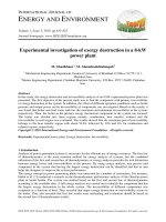
(ITER/IO Internal Report, 2013). Fig. 1 shows a part of the ITER plant
layout with the VV and ducts for connection (coloured in green and
yellow) to the VVPSS and its sub-system, that are located inside the
Drain Tank Room (DTR).
The VVPSS configuration Fig. 1(b) consists of four Suppression
Tanks (STs) with an identical volume (100 m3), an inner diameter of
2.1. Problem definition
STs operate at sub-atmospheric pressure, the latter being not standard and new operational mode for nuclear systems. In fact, the VVPSS
operation conditions differ considerably from those experienced in the
past for the suppression pools of BWR-based NPPs, operating at atmospheric pressure. Indeed, steam direct contact condensation (DCC) near
242
Nuclear Engineering and Design 335 (2018) 241–254
D. Mazed et al.
Fig. 1. a) Plant layout overview with indication of connection between the VV and the VVPSS tanks in the DTR; b) location of the VVPSS in the Drain Tank Room
tanks with indication of tanks are then functionally divided into the two categories of LLTs and SLT, and c) overview of STs and of the sparger.
therefore a proper investigation, also by executing experimental tests, is
necessary in order to support the safety design of ITER VVPSS STs and
its qualification process.
To provide further justifications to support the need to study the
DCC thermal-hydraulic conditions at STs, we have to recall that, if at
atmospheric pressure the superheated steam at, e.g., about 130 °C needs
to be cooled down to reach the condensation temperature of 100 °C
(ΔTsubcooling ≈ 30 °C), at sub-atmospheric pressure conditions, for instance 10 kPa, however, an efficient condensation of the same superheated steam requires a subcooling capacity higher than three times
(ΔTsubcooling ≈ 100 °C), to reach the condensation temperature of 33 °C
prevailing at that sub-atmospheric pressure.
Finally, by considering the lack of available experimental data on
the steam condensation at sub-atmospheric pressure condition, we
decided to perform (Mazed et al., 2016) a series of experimental tests
with a properly designed test rig at the Department of Civil and Industrial Engineering (DICI) of University of Pisa aiming:
Fig. 2. LLTs and SLT ducts lines.
– to characterize steam condensation phenomena, identifying steam
condensation regimes at sub-atmospheric conditions;
– defining the parameters that mostly influence the steam condensation process;
– to determine the efficiency of the steam condensation in water at
fixed operating conditions;
– acquiring reliable experimental data for code validation qualification.
vacuum conditions, using water closed to saturation and slightly superheated steam is not standard for traditional nuclear power systems,
whose pressure suppression systems are characterized by saturated
steam condensed at relatively high pressures and using highly subcooled water.
The DCC at the VVPSS prototypical thermal-hydraulic conditions is
not sufficiently known (as well as the condensation efficiency),
243
Nuclear Engineering and Design 335 (2018) 241–254
D. Mazed et al.
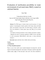
system that is shown Fig. 5. The thermally insulated condensation tank
is a 4.55 m3 stainless steel cylindrical vacuum tight vessel of 1.40 m
internal diameter, wall thickness of 8 mm and 3.2 m overall height. It is
provided with an oblong shaped manhole at the bottom, centered at the
exit sparger hole level, to allow any intervention and maintenance inside the tank. Its inner volume has been virtually subdivided by defining a pile-up of eight control volume layers, from L2 up to L9, as
indicated in Fig. 4-b. Layers L3, L4, L5, L6, L7, and L8 have a cylindrical
geometry, while the end volume layers, L2 and L9, are hemispheric.
In order to perform an accurate temperature and pressure measurement throughout the water volume the whole condensation tank
was equipped with 28 temperature sensors (TE) (uncertainties on
measurement of ± 0.1 °C) and 8 pressure transducers (PE) (uncertainties on measurement of ± 0.1 kPa), duly calibrated according to
the International standards ISO/IEC 1725.
Each inner layer (indicated in the Fig. 4-b with the letter L, in red
font, and progressive number from 3 to 8 (L3 ÷ L8)) is instrumented
with four temperature sensors, connected to the CT inner wall at a
distance of 90° to each other, and one pressure transducer. Their
longitudinal position in the condensation tank is defined like in Fig. 4-b
and is specified like in Table 1.
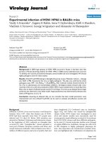
The removable sparger system, shown Fig. 5, is located inside the
CT at 40 cm from the tank longitudinal axis; it is a double walled tube.
The steam flows along an inner 2″ pipe (DN50, electrically heated
and thermally insulated) having at the lower end a cap drilled with
holes of 10 mm diameter. It is instrumented with pressure (PE101) and
temperature (TE101) sensors, positioned within the sparger tube near
the exit hole. The outside surface, covered by insulation mineral wool
(of thermal resistance is 2.85 m2 K/W and thermal conductivity is
0.035 W/(m·K)), is equipped with an electric heater system in order to
avoid steam condensation within the tube. The 4″ external tube
(DN100) isolates the sparger system from the pool water Fig. 5 shows
the top and bottom ends of sparger and the position of temperature and
pressure sensors upstream the exit holes.
The water is heated up directly by discharging the superheated
steam provided by the steam generator at full scale rate. Oppositely, the
heat can be removed directly by cooling down the water through the
chiller (30 kW cooling power, liquid refrigerant closed loop, air cooled,
AERMEC model), which operates at atmospheric pressure, or indirectly
by flowing cold water within a coil piping located on the internal wall
of the tank. This stainless steel plate heat exchanger (34 kW cooling
power, TRANTER model) allows to avoid dirty water at the exit of the
chiller (corrosion issues) feeding the tanks and restoring the initial
water temperature before each experimental test.
The water head level is measured through a high precision differential pressure sensor level (purchased from the Endress Hauser): uncertainty of measurement is ± 1 mm for all rangeability.
The FRCS is built upon two independent parallel feeding lines
(namely, line 1 and line 2). These latter (flow rate 0.30 g/s–7.5 g/s and
5 g/s–45 g/s respectively) are equipped with temperature and pressure
sensors and with mass flow rate meters.
The steam mass flow rate is monitored/controlled through a Coriolis
(in Line 2, DN15) purchased from Hendress Hauser or vortex (in Line 1,
DN40) purchased from Siemens enabling measurement with an accuracy of about 5% and 3% respectively. Inside the condensation tank, a
visualization and video recording system is also installed.
It is made from 4 high speed video cameras (GOPRO Hero4 model),
which have been thermally insulated and accommodated within vacuum tight and water proof stainless steel boxes, as shown in Fig. 6.
Three of them are positioned at the same level of the sparger exit: the
front camera is at about 1.00 m in front of the sparger exit; the left and
right cameras are at 0.72 m left and 0.72 m right from the sparger exit.
The upper camera is fixed on the top of the condensation tank (and
aligned along the axis) at about 2.40 m above the sparger exit.
Moreover, to illuminate the inside of the CT during test, in front of the
sparger exit we have installed six LED diode (strips of 2 m length and
In particular, the identification of the steam condensation regimes
at sub-atmospheric conditions was done by analogy with those determined at atmospheric pressure (Mazed et al., 2016; Liang, 1991;
Song et al., 2012) by comparing the existing experimental data to the
empirical correlations so far obtained.
The main condensation regimes expected during the system operation and the related steam condensation efficiency will allow to draw
up important engineering criteria and support the optimization of the
design of the ITER VVPSS safety system. For this purpose, an experimental test facility was built and set up with a sparger scaling factor of
1/10 the full scale size installation at ITER. This facility, even if scaled
with respect to the ITER system, provides a good representation of the
VVPSS operational conditions in terms of initial pressure in the tank
free space (close to vacuum conditions), initial water temperature,
water head level inside the tank, sparger holes dimension and steam
mass flow rate per hole.
As a first phase of the experimental campaign, about 100 condensation tests were performed to analyze the phenomenon of the
condensation of both the saturated and the superheated steam in water
at pool temperature (from 10 up to 50 °C) and sub-atmospheric pressure. In addition several water head levels, different patterns of the
sparger (with 1, 3 and 9 exit holes), and steam mass flow rate per hole
have been considered.
In what follows, the experimental set-up, the test conditions, the test
matrix and the obtained results are presented. The obtained experimental data in terms of water temperature increase, condensation efficiency and identified condensation regime are discussed in Section 5.
In this section, the comparison between the steam condensation regimes at sub-atmospheric and those observed at atmospheric pressure
(from studies available in literature) is provided.
3. Description of the experimental test facility
The experimental test facility designed and constructed at “B.
Guerrini” Laboratory of the DICI- University of Pisa is constituted by
eight sub-systems, which are:
–
–
–
–
–
–
–
–
–
The
The
The
The
The
The
The
The
The
Superheated Steam Supply System;
Flow Rate Control System (FRCS);
Condensation Tank system (CT);
Auxiliary Tank (AT);
Vacuum System (VS);
Cooler System;
Degassed Water Supply System;
Data Acquisition and Control System;
Visualization and video recording system (VVRS).
These sub-systems are interconnected each other’s as indicated in
the block diagram of Fig. 3.
The Superheated Steam Supply System is constituted by an electrical steam generator (with acronym SG001 in the block diagram of
Fig. 3) of 130 kW provided in series by a heater (6 kW), able to deliver a
maximum steam mass flow rate of 45 g/s at a pressure of 1.6 bar and
150 °C superheated steam temperature. During operation, the steam
generator automatically adjusts the power required in order to get the
requested steam mass flow according to the set point by the SCR (Silicon-Controlled-Rectifiers) regulator.
The AT is a 1 m3 stainless steel cylindrical vacuum tight vessel of
0.80 m internal diameter and 2.1 m overall height. It is designed for
conditioning the steam flow such to ensure steady state conditions prior
to start-up a test run at required test parameter values. The AT main
role is thus to avoid undesired brief transients (pressure temperature,
and steam flow rate excursions) when starting a condensation test run
within the condensation tank.
The CT consists of the condensation tank (with acronym CT101 in
the block diagram of Fig. 3, shown in Fig. 4-a, and of the inner sparger
244
Nuclear Engineering and Design 335 (2018) 241–254
D. Mazed et al.
Fig. 3. The block diagram of the experimental facility with indication of sub-systems and relating interconnections.
hammer effects and over range excursions of control parameters. An
overview of the control room equipment and of the panel screens
showing the data acquisition and control program are given in Fig. 7.
The sensors’ measurements plus the registration from the four fully
synchronized video cameras (recordings from four different points/side
views) allowed to characterize the steam condensation phenomena. As
total power of about 200 W) that have been linked vertically on the CT
inner surface as indicated in the bottom image of Fig. 6.
The data acquisition and control system program is coded upon
LabVIEW© platform. Furthermore, for a safe operation of the experimental facility, the control program integrates numerous safety and
security routines such to protect the facility integrity against water
Fig. 4. (a) The thermally insulated condensation tank and (b) the subdivision of the inner volume in layer (with sensors identification and positions) (Huang et al.,
2015).
245
Nuclear Engineering and Design 335 (2018) 241–254
D. Mazed et al.
Fig. 5. Overview of the sparger system assembly. Specifically (a) shows the top-flanged part of the system, allowing the sparger to be restrained onto the upper
hemispherical cover of condensation tank. (b) The detail of the bottom part of the sparger system: on the right it is recognisable the lower cap with 10 mm diameter
hole. (c) The technical drawing of the three configuration of the removable bottom part of the sparger; from left to the right we may observe the pattern with 1H, 3H,
and 9H respectively.
(by increasing the water head).
The test matrix consists of 105 tests that combines the following
main parameters:
a result, during each test run, more than 60 sensor signals have been
acquired simultaneously with a sampling frequency of 1 Hertz. A
dedicated Fortran program enabled to handle and process the huge
amount of data measured for each condensation test.
– Three different sparger configurations: 1, 3 and 9 holes (indicated in
what follows with notation 1H, 3H and 9H respectively), of 10 mm
diameter each.
– Three water head levels: 1.3 m, 1.6 m and 2.0 m (downstream
pressure PW effect).
– Two thermodynamic states of the steam: superheated and saturated.
– Three steam mass flow rates for each sparger configuration:
1H: 1.5, 2.5 and 5 g/s (55 tests);
3H: 4.5, 6.5 and 15 g/s (25 tests);
9H: 13.5, 22.5 g/s and 45 g/s (25 tests);
– Five initial water temperature (Tw) values: 10, 20, 30, 40 and 50 °C.
4. Test matrix and experimental procedure
The present research activity on the steam DCC will represent the
basic knowledge and the governing input for the final design of the
condensation tanks since the performed experimental tests simulated
the geometrical configuration of the condensation tanks together with
the influence of additional geometrical parameters like symmetry in the
ITER project configuration.
•
•
•
4.1. The test matrix definition
In particular, the attention was focused on the possible influence of
the sparger configuration, associated to the number of holes available
for each sparger, on the condensation efficiency. In addition, it is
worthy to remark that the sparger with multiple holes was designed
The test matrix was defined to allow the investigation of several
parameters affecting the condensation of steam in water at sub-atmospheric pressure, which are: steam mass flow rate per hole; water
temperature (subcooling parameter), and downstream water pressure
246
Nuclear Engineering and Design 335 (2018) 241–254
D. Mazed et al.
Table 1
Layer dimension and related sensor position.(*)
(*) In the four last columns, the different colors indicate the water head (WH) and how many sensors have been installed under (in water) and above (in VS) this
WH to measure temperature and pressure during the experiments.
mass flow rate. This duration was determined such to allow to measure
temperature increment ΔTw inside the CT at least twice the sensor
uncertainty (i.e., > 0.2 °C) whatever are the influencing experimental
conditions of the condensation test at hand (total mass of water, total
steam flow rate). Since the lowest initial water temperature is 10 °C, the
temperature increment is measured with an accuracy better than 2%.
If the steam mass flow rate fluctuation during the test exceeds 5% of
the required value, the test is repeated, soon after having re-established
the initial conditions (initial water temperature and water head level).
The experimental data from the temperature and pressure sensors,
the steam mass flow rate, the steam exit pressure PS (PE101, measured
within the sparger) and the downstream water pressure PW (PE103,
measured in the water) are then processed to determine the averaged
values over the test duration, and by performing Fast Fourier
Transformation (FFT) analyses (upstream and downstream pressure
oscillations). Vibration assessment performed by investigating the
sparger behaviour and the pressure oscillations during the system operation is not treated in this study (Lo Frano et al., 2018).
with the same holes diameter and pitch of the VVPSS sparger holes in
order to check the jets interaction effects.
4.2. Experimental procedure and data elaboration
The condensation tests sequence has been such to move progressively from the sparger configuration, with one hole to that with the
nine holes: indeed the sparger end cap (see previous Fig. 5) was each
time substituted. Moreover, for each sparger, we performed firstly tests
at high temperature in order to handle water with low air solubility
rates, and subsequently those at lower water temperature: the chiller
allowed to cool down the water up to the defined initial water temperature.
In order to establish the steady state regime, required by the test
conditions, the steam flow was first conditioned within the AT and,
then, injected into the CT in order to ensure that the condensation test
run is started in stationary conditions.
Each condensation test lasted generally 900 s at a constant steam
Fig. 6. Pictures showing the video record system components before the assembling (top figure), and the view of the cams position and LED stripes (bottom figure).
247
Nuclear Engineering and Design 335 (2018) 241–254
D. Mazed et al.
Fig. 7. The control room (a) and the panel screen of the acquisition and control program developed according to the test rig circuit (b) herein schematized.
experimental work are:
The uncertainty affecting the measurements was evaluated by applying the propagation of error theory and considering the bias (or
systematic errors) and random errors. Based on the calibration of sensors (that conforms to ISO/IEC 17025) and repetition of measurements,
it resulted less than 5%.
As for the recorded videos, they were of a meaningful importance
because they allowed both the visual and the qualitative analysis of the
condensing steam jet and the thermal mixing induced by the steam
discharged into the water tank at sub-atmospheric pressure condition.
Once the turbulent jet becomes an impinging jet hitting the tank
wall, it transforms into a wall flow, which is a radial motion moving out
along the wall in all the directions. Therefore, it is very important to
identify the geometrical characteristics of the condensing jet, since it
allows to determine the area of the vapour-water interface surrounding
the vapour core of the steam plume, that, in turn, enables to evaluate
experimentally the heat transfer coefficient through this interface.
• the water average temperature increase (ΔT );
• the longitudinal and radial ΔT profiles;
• the pressure increase (ΔP ) in the vacuum, free space volume above
the water head;
• the geometrical characteristics and spatial extension of the condensing steam jet plume;
• the established steam condensation regime.
W
W
FS
A summary of the results obtained from tests carried out for a water
head level of 1.3 m and H1, H3 and H9 is provided in Table 2. Similar
data have been of course obtained for different WH (ranging from 1.3 m
to 2 m) in order to study the downstream pressure effect at sub-atmospheric condition.
The physical mechanism that characterises the condensing steam jet
is explained by considering that when a condensing steam jet penetrates
into the water, it entrains liquid from the pool water, inducing a water
turbulent motion.
Basically, the energy associated to the steam condensation is
5. Experimental results
The
most
important
parameters
examined
in
the
present
248
Nuclear Engineering and Design 335 (2018) 241–254
D. Mazed et al.
Table 2
Results for WH = 1.3 m and different sparger configurations.
WH = 1.3 m
1H
3H
9H
TW [°C]
Gs [kg/m s]
PW [kPa]
Steam Cond. regime
θ [°C.kg/kg]
ΔTw [°C]
PSF [%]
θ [°C.kg/kg]
ΔTw [°C]
PSF [%]
θ [°C.kg/kg]
ΔTw [°C]
PSF [%]
10
20
30
40
50
18.1
18.22
17.36
19.36
23.36
27.08
TC
TC
TC
TC
BCO
749.2
460.6
505.4
357.7
436.9
0.21
0.14
0.22
0.16
0.13
98.3
99.9
99.9
98.0
100.0
704.7
661.0
624.4
582.0
550.2
0.92
0.86
0.82
0.77
0.72
99.9
99.4
99.9
99.9
99.9
639.0
631.5
611.0
584.4
558.6
2.52
2.48
2.37
2.29
2.28
100.0
100.0
100.0
100.0
100.0
10
20
30
40
50
31.8
17.01
17.36
18.42
24.33
27.22
SC
SC
SC-CO
CO
CO
660.6
596.1
588.3
474.8
506.7
0.48
0.43
0.43
0.35
0.37
99.8
100.0
99.9
98.8
99.9
651.9
651.0
613.9
585.9
552.0
1.21
1.23
1.16
1.10
1.04
100.0
99.9
99.9
99.9
99.9
619.8
606.9
590.3
569.0
545.6
4.05
3.96
3.88
3.71
3.66
100.0
100.0
100.0
100.0
100.0
10
20
30
40
50
63.5
17.36
18.04
20.42
22.2
26.86
SC
SC
SC
SC
CO
625.9
615.8
626.7
563.6
529.2
0.91
0.89
0.90
0.83
0.78
99.9
99.8
100.0
99.9
99.9
624.3
601.5
586.1
561.2
540.6
2.71
2.61
2.54
2.47
2.38
100.0
100.0
100.0
100.0
100.0
566.5
544.1
510.5
506.1
497.2
6.49
6.46
6.02
6.03
5.96
100.0
100.0
100.0
100.0
100.0
2
Fig. 8. Trend of the water temperature increase (for WH = 1.3 m) for different steam mass flow rates, and sparger holes configuration (1H, 3H and 9H). Psat indicates
the saturation pressure in free space volume at injected steam.
1. the mean water temperature increase (ΔTW); and
2. the Pressure Suppression Factor (PSF).
transferred in the proximity of vapour-water interface: thus, the condensation rate depends on the interfacial area of the vapour core of the
plume. The interfacial heat transfer coefficients and mass transfer are
determined based on the three governing parameters:
Because of DCC (heat energy transferred from the steam to the
water until the thermal equilibrium is reached: reaching saturation
temperature, the steam suddenly condenses and transfers to water the
condensation latent heat), it is possible to determine the steam condensation rate and the condensation efficiency at the prevailing conditions on the basis of the accurate measurement of ΔTW before and
after the event of steam discharge. This was possible at any time thanks
to the many temperature sensors located in each water condensation
layer (see Fig. 4-b). ΔTW is obtained by measuring the variation of the
average water temperature (Tave), weighted on the corresponding water
mass (Section 3 for more details), as:
• water subcooling ΔT (= T -T , the difference between the steam
and water temperatures);
• steam mass flux G (= Q /A, where Q is the steam mass flow rate
and A the exit hole area);
• downstream pressure P (in water, at exit hole level).
sub
S
s
s
W
s
W
5.1. Condensation efficiency
To assess the steam condensation efficiency, we need to define the
two parameters:
ΔTW = (Tave) fin−(Tave) in
249
(1)
Nuclear Engineering and Design 335 (2018) 241–254
D. Mazed et al.
Fig. 9. PSF versus the initial water temperature for different test parameters.
as follows:
ΔP
PSF(%) = 100·⎜⎛1− net ⎞⎟
Pg-eq ⎠
⎝
(2)
where Pg-eq is the pressure-equivalent of the discharged steam or gas,
generally speaking (calculated based on the following Eq. (3)).
If we assume that all the steam mass (mst), integrated over the
duration of the experiment, occupies the free volume (VVS) in the CT,
therefore based on the temperature measured (TVS) in this free volume,
it is possible to evaluate the pressure-equivalent of the discharged
steam (Pg-eq) according to the perfect gas law (assuming the steam as
ideal gas):
Pg-eq = n
mg RTVS
RTVS
=
VVS
Mg VVS
(3)
where n is the number of moles of the gas, MH2O is the water molar
mass, and R the perfect gas constant.
ΔPnet is the net pressure change in the vacuum space to be evaluated
as:
Fig. 10. Condensation regime map for a single steam jet in water pool at atmospheric pressure (experimental data from Song et al., 2012).
ΔPnet = (PVS) fin−(PVS)in
According to integral approach to provide accurate measurement of
temperature, a weighting over the annulus of water to which TE refers
is used (annulus may be defined based on dimensions provided in
Fig. 4(b) (Al-Shammari et al., 2004). Fig. 8 shows the behaviour of ΔTW
as a function of TW in the range 10–50 °C, for several steam mass flow
rates, and sparger configurations.
Finally as for ΔTW behaviour, we observed that no appreciable
differences appear between superheated and saturated steam (differences are in the uncertainty range, i.e., ± 0.1 °C), whatever WH, so the
total mass of water in the tank, and initial TW. Taking into account the
total mass of water (MW) inside the CT, and the total discharged steam
mass, mst, the subcooling capability of the system is identified through
θ, which was evaluated by considering the increase of the initial water
temperature (TW) in 1 kg of water as a consequence of 1 kg of discharged steam.
In order to characterize the efficiency of the steam condensation in
the water tank it has been identified the PSF, which can be determined
(4)
The PSF is based on the concept that if the steam was made from
non-condensable gas instead of water vapour, the Pg-eq should increment correspondingly the PVS of almost the same amount.
The trend of the PSF values for WH = 1.3 m is shown in Fig. 9. All
these values have been found very close 100% (with uncertainties ±
0.1%) implying very close to a total condensation of the steam. As a
confirmation of that there is the evidence obtained performing proper
test injecting air instead of steam: the PSF was almost zero.
5.2. Condensation regime
In what follows, the steam condensation regimes as determined
from the performed experimental tests are presented. At sub atmospheric pressure they resulted to be mainly governed by the water
temperature (Tw) and by the ratio of steam mass flux to downstream
pressure (Gs/PW): boundaries delimiting the condensation regions (the
stable steam jet behaviour from the unstable one), for a given steam
250
Nuclear Engineering and Design 335 (2018) 241–254
D. Mazed et al.
Fig. 11. (a) The map of main condensation regime: on the order it is represented Tw (°C), while in the abscissa it is given the steam mass flux (kg/m2 s). (b) Photos of
the characteristic shape of the steam jet at exit hole for each identified condensation regime (Lo Frano et al., 2017) and test parameters.
251
Nuclear Engineering and Design 335 (2018) 241–254
D. Mazed et al.
Fig. 12. The condensation regime map at sub-atmospheric pressure. The test points are shown in open square symbols.
Fig. 13. Schematic representation of the steam jet plume during DCC, including steam jet regions and geometrical parameters.
mass flux and water temperature are so determined.
The six main condensation regimes that we have identified are
classified by analogue with those provided by Liang (1991) (who has
carried out an analytical and experimental study on the steam condensation at atmospheric pressure) and by Song et al. (2012) (Fig. 10).
Therefore based on the observed characteristic shape of the condensing
steam jet at atmospheric pressure (image analysis of video recorded),
we identified the following condensation regimes (CR):
•
•
• Chugging (C): this regime is identified when the vapour-water in•
•
•
terface locates alternatively inside and outside the sparger. It is
characterized by high instabilities without developed steam jet.
Transitional Chugging (TC): this regime is observed when the vapour-water interface locates outside the sparger in the water of the
tank, and the vapour core is characterized by short variation in its
dimensions.
Bubbling Condensation Oscillation (BCO): this regime takes place
when the steam condenses in form of bubbles of different diameters,
oscillating in dimensions and in directions.
Condensation Oscillation (CO): this regime is characterized by the
formation of a shape varying condensing steam jet plume, oscillating in the longitudinal direction.
Stable Condensation (SC): this condensation regime is reached when
a stationary condensing steam jet is established and is characterized
by its stability in time and space constancy. The condensing jet
plume doesn’t change neither in length nor in radial direction.
Interfacial Oscillation Condensation (IOC): this extreme condensation regime is characterized by its high instability. It shows an intermittent and random process of disruption-formation of the separation interface between the steam core and water. It is
characterized by a random changing plume shape.
Fig. 10 shows for instance the general condensation map of ChulHwa Song et al. that was obtained for a wide range of steam mass flux
252
Nuclear Engineering and Design 335 (2018) 241–254
D. Mazed et al.
Fig. 14. Steam jet penetration length versus the water temperature for different Gs and WH.
5.3. Jet plume expansion studies in stable condensation
and water temperature and atmospheric pressure (Song et al., 2012).
When steam condensation takes place at atmospheric pressure, the CR
boundary are depending on the operating pressure.
Fig. 11(a) shows a similar steam condensation map with the indication of condensation region we derived from the performed experimental campaign, while Fig. 11(b) provides some photographs of
the typical shape of the condensing steam plume for CR.
Fig. 12 shows the condensation regime map we determined from the
experiments performed at sub atmospheric pressure for all the examined ranges of water temperature (10–50 °C) and steam mass flux
(12–64 kg/m2 s). Even though the steam mass flux range is narrower,
compared to that commonly obtained at atmospheric pressure, four
different steam condensation regimes (Lo Frano et al., 2017) were
identified as follows:
–
–
–
–
When analysing the spatial expansion of the condensing jet in the
stable condensation regime, one can distinguish three main regions, as
shown in Fig. 13: a region of steam jet expansion R1, followed by a
region of steam jet contraction R2, and by a further turbulent jet region
R3 (de With, 2009).
In the region R1, close to the hole exit, the steam is released with a
pressure (PS) higher than the downstream pressure (PW), characterized
by the pressure ratio γp (=PS/PW).
In R1 the steam jet expands radially to reach an equilibrium diameter δ, slightly higher than the exit hole diameter, over a longitudinal
penetration xδ in water.
In R2 region, the steam jet enters a contraction phase as it progresses still further to deeply penetrate the subcooling water (length of
jet is l-xδ). Consequently, the steam temperature decreases abruptly
close to the lateral surface of the vapour cone, due to the direct contact
with the water, reaching a local equilibrium. As a result, the local steam
density decreases more and more quickly and, close to the proximity of
the vapour-water interface, it reaches the local saturation temperature,
Tsat (Pw).
The steam jet plume collapses in the turbulent jet region R3, where
it is disrupted in small spherical bubbles. Because of their small size,
bubbles condense efficiently in the bulk subcooled water, while rise
upward towards the water head, following lower pressure gradients.
The (measured) steam jet penetration is given in terms of the dimensionless ratio L/ dh, where L is the steam jet length (R1 plus R2) and
dh is the sparger hole diameter (Fig. 14). For a constant steam mass flux,
the steam jet penetration increases with TW and decreases as WH increases. Indeed, if we assume a constant heat transfer for fixed PW and
GS, the area of the vapour-water interface increases with the increase of
jet, so as the temperature.
Bubbling Condensation Oscillation (BCO);
Transitional Chugging (TC);
Stable Condensation (SC);
Condensation Oscillation (CO).
The pressure-scaling factor was precisely estimated to be about 1/8.
This indeed determines a contraction of the steam mass flux range in
the same ratio and results in modification of condensation regime
(visible by comparing Fig. 10 with Fig. 12) to get the stable condensation (SC) is about 240 kg/m2 s. At sub-atmospheric condition,
GSmin is shifted downward to about 30 kg/m2 s, leading to a contraction
of the minimum steam mass flux range by a ratio 1/8 (=30/240).
As a results, we conclude that while at atmospheric pressure below a
steam mass flow value of 70 kg/m2 s, we observe only the chugging
regime (label C), as can be seen in Fig. 10, whereas at sub-atmospheric
pressure condition up to four different condensation regimes can be
observed within this range as shown in Fig. 12. From that, it appears the
importance of pressure (and of its effects) and in turn the importance of
the present experimental investigation. From the foregoing, we may
conclude that at conditions foreseen for the ITER-VVPSS operation, the
stable condensation regime (Fig. 12) requires minimum Qs of about
25 kg/m2 s for Tw below 50 °C.
6. Summary
The performed tests permitted to draw up the following conclusions:
253
Nuclear Engineering and Design 335 (2018) 241–254
D. Mazed et al.
– The steam was efficiently condensed in all tests.
– The water temperature increase, for the same mass flow rate and the
same test duration, does not depend on the initial water temperature
(in the range 10–50 °C).
– No “interference” between adjacent steam jets appears in the
sparger configuration with multiple holes, since the observed steam
bubble coalescence was very negligible.
– The water temperature increase depends mainly on total thermal
input.
– For examined temperature test conditions, as Pw increases, the six
condensation regimes moves to high Gs values, showing the influence of pressure in the vacuum space of the tank on the condensation regimes.
– The steam condensation regime is mainly governed by the water
temperature, downstream pressure and the steam mass flow rate per
hole.
non-condensable gases in a vertical tube. Desalination 169, 151–160.
Aya, I., Nariai, H., 1991. Evaluation of heat transfer coefficient at direct condensation of
cold water and steam. Nucl. Eng. Des. 131, 17–24.
Chen, L.D., Faith, G.M., 1982. Condensation of submerged vapor jets in subcooled liquids.
J. Heat Transfer 104, 774–780.
Chun, M.H., Kim, Y.S., Park, J.W., 1996. An investigation of direct condensation of steam
jet in subcooled water. Int. Commun. Heat Mass Transfer 23 (7), 947–958.
Cumo, M., Farello, M., Ferrari, G.E., 1978. Heat transfer in condensing jets of steam in
water. Proc. 6th Int. Heat Transfer Conf., Toronto, vol. 5, 101–106.
de With, A., 2009. Steam plume length diagram for direct contact condensation of steam
injected into water. Int. J. Heat Fluid Flow 30, 971–982.
Del Tin, G., Lavagno, E., Malandrone, M., 1983. Thermal and Fluid-dynamic features of
vapor condensing jets. Heat Technol. 1 (1), 13–35.
Fukuda, S., 1982. Pressure variation due to vapor condensation in liquid (II): phenomena
at large vapor mass flow rate. J. At. Energy Soc. Jpn. 24 (6), 466–474.
Hong, S.J., et al., 2012. Condensation dynamics of submerged steam jet in subcooled
water. Int. J. Multiph. Flow 39, 66–77.
Huang, J., et al., 2015. Review of vapor condensation heat and mass transfer in the
presence of non-condensable gas. Appl. Therm. Eng. 89, 469–484.
ITER/IO Internal Report. Preliminary Design Review, L8EUP5, 15 November 2013.
Kerney, P.J., Faeth, G.M., Olson, D.R., 1972. Penetration characteristics of submerged jet.
AIChE J. 18 (3), 548–553.
Kim, Y.S., et al., 1997. An experimental investigation of direct condensation of steam jet
in subcooled water. J. Korean Nucl. Soc. 29 (1), 45–57.
Liang, K.S., 1991. Experimental and analytical study of direct contact condensation of
steam in water (Ph.D. thesis). Massachusetts Institute of Technology.
Lo Frano, R., et al., 2016. Fluid dynamics analysis of loss of vacuum accident of ITER
cryostat. Fusion Eng. Des. 109–111, 1302–1307.
Lo Frano, R., et al., 2017. Experimental investigation of functional performance of a
vacuum vessel pressure suppression system of ITER. Fusion Eng. Des. 122, 42–46.
Lo Frano, R., et al., 2018. Investigation of vibrations caused by the steam condensation at
sub-atmospheric condition in VVPSS. Fusion Eng. Des. />fusengdes.2018.05.031. (in press).
Mazed, D., et al., 2016. Experimental study of steam pressure suppression by condensation in a water tank at sub-atmospheric pressure. Proceedings of 24th International
Conference on Nuclear Engineering, Charlotte, North Carolina, USA, June 26–30,
2016.
Song, C.-H., et al., 1998. Characterization of direct contact condensation of steam jets
discharging into a subcooled water. Proc. IAEA Tech. Committee Mtg., PSI, Villigen.
Song, C.H., Cho, S., Kang, H.S., 2012. Steam jet Condensation in a pool from fundamental
understanding to engineering scale analysis. J. Heat Transfer 134 Transactions of the
ASME-031004-2.
Stanford, L.E., Webster, C.C., 1972. Energy Suppression and Fission Product Transport in
Pressure Suppression Pools. ORNL-TM-3448. .
Tsai, S.S., Kazimi, M.S., 1976. The Potential for Penetration of a Hot Vapor Jets into a
Subcooled Liquid. ASME 76-WA/HT-78. .
Young, R.J., Yang, S.K., Novonty, J.L., 1974. Vapor liquid interaction in a high velocity
vapor jet condensing in a coaxial water flow. In: Proc. 5th Int. Heat Transfer Conf.,
Tokyo, vol. 3. pp. 226–230.
Zhu, Q., et al., 2013. Experimental study on direct contact condensation of stable steam
jet in water flow in a vertical pipe. Int. J. Heat Mass Transfer 66, 808–817.
Within the investigated conditions, we found that the stable condensation regime requires a minimum mass flow rate per hole of about
2.5 g/s for a water temperature of 10 °C. This critical steam flow rate
per one hole increases with increasing water temperature.
Ongoing tests will allow to study especially the pressure effects,
including structural-dynamic ones (vibrations), which play an important role during the steam condensation. We plan also to investigate
the stable condensation regime for extend values of temperature
(30–80 °C) and downstream pressure (30 kPa–85 kPa).
Acknowledgements
The authors would like to acknowledge Mr. M. Meekins for his
valuable suggestions and contribution and all the DICI’s technicians for
the technical support during the experimental campaign.
Disclaimer
The views and opinions expressed herein do not necessarily reflect
those of the ITER Organization.
References
Al-Shammari, S.B., et al., 2004. Condensation of steam with and without the presence of
254