On the dose fields due to activated cooling water in nuclear facilities
Bạn đang xem bản rút gọn của tài liệu. Xem và tải ngay bản đầy đủ của tài liệu tại đây (3.01 MB, 14 trang )
Progress in Nuclear Energy 117 (2019) 103042
Contents lists available at ScienceDirect
Progress in Nuclear Energy
journal homepage: www.elsevier.com/locate/pnucene
Review
On the dose fields due to activated cooling water in nuclear facilities
Andrej Žohar, Luka Snoj
T
∗
Jožef Stefan Institute, Jamova cesta 39, SI-1000, Ljubljana, Slovenia
ARTICLE INFO
ABSTRACT
Keywords:
Activated cooling water
PWR
Fusion reactor
MCNP
Cooling pipes
Steam generator
Activated cooling water in nuclear facilities can present a significant radiation source around primary cooling
system causing radiation damage to electrical components, increasing doses to personnel and in the case of
fusion facilities additional heating to superconducting coils. This paper focuses on activation of oxygen isotopes
in water and decay of this activated isotopes, i.e. 16N, 17N and 19O. An analysis of activation of water in pressurized water reactors and in fusion reactors was performed. Different evaluated nuclear data libraries were used
in activation calculations (ENDF/B-VIII.0, FENDL-3.1b, JEFF-3.2 and TENDL-2015). The calculated activation
rates with different nuclear data libraries agree well for the 16O(n,p)16N reaction and significantly differ for 17O
(n,p)17N and 18O(n,γ)19O reactions. In fusion reactor the specific activity of activated water isotopes is in the
order of 1013 Bq/m3/MW, which is five orders of magnitude higher compared to specific activity in a typical
fission pressurized water reactor, amounting to 109 Bq/m3/MW. The results of specific activity of cooling water
were used to perform parametric analysis of dose rates around pipes of cooling system and dose field around a
steam generator in a pressurized water reactor as a representative of heat exchangers. The analysis of dose rates
around pipes include pipes featuring 1 mm to 8 cm thick walls and from 0.5 cm to 60 cm water radius. Results
can be used to estimate dose rates for all studied isotopes, provided the specific activity is known. For heat
exchangers the decay of 16N contributes majority to the dose rates in the air surrounding them while 17N and 19O
decay contributes together less than 0.1%. For a typical 2 GW thermal power two loop pressurized water reactor
the dose rates in air surrounding the stream generator are in the order of several mSv/h.
1. Introduction
Water is cooling fluid in many nuclear facilities, such as fission
nuclear reactors and some fusion reactors. In fission reactors water is
activated when passing through the reactor core, in fusion reactors
however water is activated when cooling the blanket, or other components of the reactor such as diagnostic equipment. Activation of
water consist of activation of oxygen and hydrogen as primary constituents of the H2O molecule, activation of dissolved gasses, corrosion
products and additions to water and fission products in fission reactor.
As all the latter are case specific, in this paper we will focus on activation of pure H2O only. After being irradiated and activated the
cooling water flows through the primary cooling circuit, commonly
outside the primary biological shielding surrounding the reactor vessel.
There the activation products decay, emit radiation, which causes radiation damage to electrical components, increasing doses to personnel
working around the cooling circuit and in the case of fusion facilities
causes nuclear heating of various cold components such as superconducting coils cooled by liquid helium (Iida et al., 1997).
Decay of activated cooling water can also be used to obtain
∗
important parameters of the heat producing component. In nuclear
power plants the decay of activated water is used to detect leakage of
primary cooling system in the secondary cooling system (IAEA, 2000).
Activated water can also be used to determine water flow and power of
the reactor (Tsypin et al., 2003). In the case of fusion reactors the
neutron yield of the reactor can be measured with the use of activated
water (Nishitani et al., 2003). There are several papers on measurement
of activation of cooling water in fission power plants and research reactors (Guo et al., 2018; Stepišnik et al., 2009) where the measurement
are performed regularly for education of university students. For fusion
reactor only one experiment on the activation of water was performed
at the JAERI FNS facility in Japan (Uno et al., 2001). Activated cooling
water is also present in spallation source facilities (Santoro et al., 1999).
The main contributors to the activity of clean cooling water are
radioactive isotopes of oxygen and nitrogen produced by activation of
oxygen isotopes in the cooling water, i.e. 16N, 17N and 19O. Majority of
studies dealing with activation of cooling water and dose fields due to
decay of activated water focuses on isotopes 16N and 17N (Blakeman
et al., 2007; Santoro et al., 1997) while the majority neglects the effects
of isotope 19O due to lower energies of gamma radiation emitted in
Corresponding author.
E-mail addresses: (A. Žohar), (L. Snoj).
/>Received 19 December 2018; Received in revised form 19 April 2019; Accepted 25 April 2019
Available online 16 May 2019
0149-1970/ © 2019 The Authors. Published by Elsevier Ltd. This is an open access article under the CC BY-NC-ND license
( />
Progress in Nuclear Energy 117 (2019) 103042
A. Žohar and L. Snoj
decay and negligible activity compared to isotope 16N. However in this
paper activation and dose rates of all three isotopes of activated oxygen
in cooling water are studied. As hydrogen has two stable isotopes, 3H is
also produced in cooling water from 2H activation. However, as 3H halflife is in long compared to other activated isotopes and practically no
gamma rays are emitted at decay, 3H dose rate contribution are neglected in this paper as they are in other papers.
The analysis presented in this paper focuses on calculating activation of oxygen isotopes and the dose fields around primary cooling
pipes and heat exchangers of nuclear devices by using Monte Carlo
particle transport code MCNP (Goorley et al., 2012). In the first part of
the paper the neutron activation data, comparison of cross-sections for
activation between different evaluated nuclear data libraries and results
of activation calculations for fission and fusion reactors are presented.
The second part of the paper presents the parametric analysis of dose
rates in the air surrounding pipes with different wall thickness and
water diameter and equivalent biological dose rates in the air surrounding a heat exchanger are presented. For the model of a heat exchanger a vertical steam generator in a typical 2 GW thermal power
pressurized water reactor was used. Dose rates presented in the paper
are the H*(10) ambient dose equivalent for biological dose rates and
dose rates in silicon for electronic components.
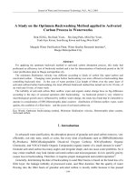
Fig. 1. Cross-section energy dependence for activation of oxygen nuclide taken
from the JEFF-3.2 data library (OECD/NEA Data Bank, 2014).
As there are many different evaluated cross-sections for the above
mentioned water activation reactions in different evaluated nuclear
data libraries, the cross-sections can be significantly different. In this
paper cross-sections from four different libraries were used: ENDF/BVIII.0 (Brown et al., 2018), JEFF-3.2 (OECD/NEA Data Bank, 2014),
FENDL-3.1b (Koning and Trkov, 2016) and TENDL-2015 (Koning et al.,
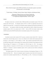
2015). Cross-section for activation of 16O (Fig. 2) in all studied libraries
is the same as it is derived from the same experimental data (Nelson and
Michaudon, 1999).
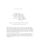
For 17O activation however the cross-sections differ between libraries as presented in Fig. 3. The cross-section in JEFF-3.2 library is
taken from TENDL-2012 and cross-section in FENDL-3.1b is taken from
TENDL-2010, which are predecessors of TENDL-2015 library. Evaluated cross-sections in TENDL libraries are based on computations by
software for simulation of nuclear reactions TALYS (Koning and
Rochman, 2012). The TENDL-2010 library is based on TALYS 1.20
version, TENDL-2012 is based on TALYS 1.50 version and TENDL-2015
is based on the TALYS 1.74 version for computation of cross-sections.
Due to this the cross-sections between this three libraries are similar
unlike the cross-section from ENDF/B-VIII.0 library, which is taken
from ENDF/B-V library which was released in 1978 and is based on
computations by MODNEW (Uhl, 1972) and measurements performed
by Menlove (Menlove et al., 1970).
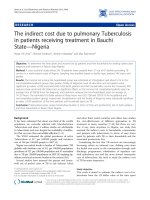
In Fig. 4 the cross-sections for reaction 18O(n,γ)19O from all studied
evaluated nuclear data libraries are presented. With the release of the
ENDF/B-VIII.0 evaluated nuclear data library the cross-section for activation of 18O was added. The cross-section is based on the
2. Neutron activation of water
Oxygen and nitrogen activated isotopes in cooling water are produced from activation of oxygen isotopes via the 16O(n,p)16N, 17O
(n,p)17N and 18O(n,γ)19O reactions. Activated isotopes in cooling water
decay by emitting various decay products with different energies.
Summarized data is presented in Table 1 (Chadwick et al., 2011). The
marked energies in table present the dominant energies of decay pro16
ducts emitted at decay. As 16N decays via decay path 16N
O + γ,
high energy gamma rays are emitted (E = 6.13 MeV) with half-life of
16
O + n + γ with half-life of
7.13 s 17N decays via decay path 17N
4.14 s.
Emitted neutrons can activate components outside the primary
circuit and produce neutron induced gamma-rays. Activated isotope
19
19
O has a half-life of 26.9 s and decays via decay path 19O
F + γ.
16
16
17
17
Reactions O(n,p) N and O(n,p) N are threshold reactions with
energy threshold at 10 MeV and 8 MeV respectively. Reaction 18O
(n,γ)19O already takes place at thermal energies as presented in Fig. 1.
Due to threshold reactions the activation of water is expected to be
higher in fusion reactors like ITER compared to fission reactors due to
higher neutron energies (14 MeV neutrons from deuterium-tritium fusion).
Table 1
Summarized data of activated isotopes of cooling water obtained from ENDF/B-VII.1 data library (Chadwick et al., 2011). The marked energies present the dominant
energies of decay products.
2
Progress in Nuclear Energy 117 (2019) 103042
A. Žohar and L. Snoj
TALYS 1.64 version and TENDL-2015 is based on the TALYS 1.74
version for computation of cross-sections. As in the case for activation
of 17O the cross-section for activation 18O taken from the ENDF/B-VIII.0
library differs significantly compared to cross-sections in other studied
nuclear data libraries. The difference in cross-section between other
studied libraries is in the epithermal region at around 0.08 MeV. In this
region the cross-section for 18O(n,γ)19O from FENDL-3.1b and TENDL2015 libraries exhibit a resonance peak, while the cross-section from
JEFF-3.2 library has no peak. Due to this the calculated reaction rates
are expected to be higher with the use of FENDL-3.1b and TENDL-2015
library.
3. Activation of cooling water
It is difficult to measure the absolute value of activity of activated
isotopes in cooling water in nuclear facilities due to short decay times of
isotopes and high energy radiation which can cause high dose rates.
Another difficulty is the placement of large detectors (e.g. High Purity
Germanium detector) close to the primary cooling system for accurate
measurements as the systems are normally shielded. The easiest way to
determine the absolute value of isotope activity is by calculations from
parameters of nuclear facility. The change of specific activity of a studied isotope in the cooling water a with time is described by:
Fig. 2. Cross-sections for reaction 16O(n,p)16N taken from ENDF/B-VIII.0, JEFF3.2, FENDL-3.1b, TENDL-2015 libraries and experimental results from EXFOR
database.
a (t ) = F (1
(1)
t ),
e
−1
where λ is a decay constant [s ] and F is an average reaction rate in
region of interest over irradiation time which is described by:
F=
t
V
(r, E , t ) i (E ) n (r , t )dE dV dt ,
0
(2)
where the (r, E , t ) is the neutron flux at position r , i (E ) is the microscopic cross-section for studied reaction and n (r, t ) the number
density of target atoms at position r .
In nuclear facilities cooling water circulates in the primary cooling
system and is exposed to neutron flux for a short time. Hence the
change in specific activity of studied isotope is described using a system
of equations:
Fig. 3. Cross-sections for reaction 17O(n,p)17N taken from ENDF/B-VIII.0, JEFF3.2, FENDL-3.1b, TENDL-2015 libraries and experimental results from EXFOR
database.
ao = ai e
ti
ai = ao e
T,
+ F (1
e
ti)
(3)
where ao is the specific activation of coolant on the outlet of heat
producing component, ai is the specific activation of coolant on the
inlet of heat producing components, ti is the exposure time and T is
circulation time the coolant needs from the outlet to the inlet of heat
producing component.
From the eq. (3) the equilibrium value of specific activity at the
outlet of the heat producing component can be obtained:
ao = F
1
1
ti
e
(ti + T )
e
.
(4)
In eq. (4) the F is the average reaction rate over whole heat producing component. The intensity of neutron fluxes as well the energy
spectrum can significantly change through the heat producing component. This changes can be taken into account by dividing the heat
producing components in smaller sections with similar neutron fluxes
and energy spectrum in which the reaction rates are calculated. In
general there are n equations for n regions in the heat producing
component plus one equation for the region outside the heat producing
component. The general form of the system of equations is:
Fig. 4. Cross-sections for reaction 18O(n,γ)19O taken from ENDF/B-VIII.0, JEFF3.2, FENDL-3.1b, TENDL-2015 libraries and experimental results from EXFOR
database. The cross-sections from FENDL-3.1b and TENDL-2015 library are
similar except in the high energy region (above 30 MeV) and are due to this
overlapped in the above graph.
Moghabghab resonance parameters below 5 MeV (Mughabghab, 2006)
while above 5 MeV the cross section is based on J. Kopecky and D.
Nierop evaluation for EAF-3 library. The cross-section in the JEFF-3.2
library is taken from the TENDL-2012 while the cross-section in the
FENDL-3.1b library is taken from the TENDL-2014 library. The TENDL2012 library is based on TALYS 1.50 version, TENDL-2014 is based on
a1
= an + 1 e
t i1
+ F1 (1
e
t i1)
an
= an 1 e
t in
+ Fn (1
e
t in)
an + 1 = an e
T.
(5)
From eq. (5) the equilibrium of activity of isotope at the outlet of
heat producing component (an ) can be calculated.
3
Progress in Nuclear Energy 117 (2019) 103042
A. Žohar and L. Snoj
As there are many different nuclear facilities where cooling water is
activated a general analysis of activation of water in each of them is
difficult to perform. In this paper an analysis of activation of cooling
water in a typical PWR and fusion reactor is presented. PWR reactor
was chosen as a representative of fission reactors as they are the most
common type of fission power reactors.
neutron flux is highest. Two orders of magnitude lower reaction rates
are in the downcomer while in lower and upper plenum the reaction
rates are five orders of magnitude lower as in the core due to support
structures in lower plenum and control rods in upper plenum. The
uncertainties in the calculation results are due to systematic error of
Monte Carlo calculation, uncertainty in the model and uncertainty of
nuclear data. However, only the Monte Carlo statistical uncertainties
are presented in Table 2. For lower and upper plenum the greatest
contribution to uncertainty is the Monte Carlo statistical uncertainty.
To improve the statistic of simulation the calculation times would need
to be extended. However, the contribution to the total reaction rate
from this two regions is negligible compared to the contribution of the
core and additional calculation time would not change the final result
significantly.
For calculation of specific activity the total value of reaction rates
are needed but the spectral analysis of reaction rates were also performed. The results of reaction rate spectra in core for some libraries are
presented in Fig. 7. For activation of 18O results of reaction rate spectra
in core from two different libraries are present to show the effect of
additional resonance peak in cross-section in TENDL-2015 library.
From calculated reaction rates and exposure times the equilibrium
specific activity at the outlet of the reactor vessel was calculated using
eq. (5) and the obtained values for all studied nuclear data libraries are
presented in Fig. 8. The most activated isotope of cooling water is 16N
due to high natural abundance and higher cross-section for reaction.
The equilibrium specific activity is four orders of magnitude higher
than equilibrium specific activity of 17N and two orders of magnitude
higher than equilibrium specific activity of 19O. Due to differences in
cross-section for activation of 17O the equilibrium specific activity of
17
N obtained with the ENDF/B-VIII.0 library is by a factor of three
higher compared to results obtained with other libraries. The equilibrium specific activities of 19O obtained with libraries TENDL-2015 and
FENDL-3.1b are by a factor of three higher than equilibrium specific
activity obtained with the use of JEFF-3.2 library due to resonance peak
in the cross-section at epithermal energy. Despite significant differences
in cross-section for activation of 18O in ENDF/B-VIII.0 library the
equilibrium specific activity is comparable to results obtained with the
use of TENDL-2015 and FENDL-3.1b. This is due to the resonance peaks
at fast neutron energies.
3.1. Activation of cooling water in PWR
To obtain the absolute value of specific activity of activated isotopes
of cooling water at the outlet of heat producing component, which in
the case of PWR is the reactor vessel, from eq. (4) some parameters are
needed. The parameters are the exposure times of cooling water to
neutron flux, circulation time and the reaction rates. The exposure time
and circulation time can be determined from volume flow rate of
cooling water and volume of it in different regions. In the studied case
the circulation time of cooling water was calculated to be around 8.1 s,
while the exposure time was calculated to be around 4.2 s of this 1.4 s to
high neutron flux in reactor core.
The reaction rates were calculated by the Monte Carlo particle
transport using the MCNP code. A geometrical model of a typical 2 GW
two loop PWR reactor vessel was constructed in MCNP. The model is
presented in Fig. 5 and neutron spectra for all studied regions is presented in Fig. 6. The reaction rates in the reactor vessel were calculated
as follows. The reactor vessel was divided in four sections: downcomer,
lower plenum, core and upper plenum and then the section averaged
reaction rates were calculated by multiplying the neutron flux calculated by the track length estimator (F4 tally in MCNP) with the corresponding cross-section. The reaction rates were calculated using all
studied nuclear data libraries and density of water at 600 K. Results of
average reaction rates in regions for some libraries are presented in
Table 2. The highest reaction rates are in the reactor core where the
3.1.1. Time dependence of specific activity
Results of specific activity presented in Fig. 8 present the equilibrium value. However, during start-up, shutdown and power changes of
reactor the value of specific activity changes. The behaviour in specific
activity can be simulated using the calculated reaction rates in specific
areas. This is described with a set of eq. (6) (Žohar and Snoj, 2016):
A o (t ) =
F4 (1
e
t ),
F3 (1
e
t )e
t i3
(1
e
t i 4),
N
i=0
ae
iT ,
t < ti 4
+ F4
ti 4
t
t < ti3
ti 4 + ti3 + ti2 + ti1 and N T
t
(6)
where a is the saturated value of specific activity after one cycle at the
outlet of reactor vessel. The first equation in eq. (6) presents the specific
activity produced in region 4 (upper plenum). The second equation
presents the saturated specific activity produced in region 4 plus specific activity produced in region 3 (reactor core). The equations follow
this order until the time the cooling water goes through the whole reactor vessel. After that the last equation describes the specific activity
behaviour.
The first analysis performed was the change of specific activity of all
activated isotopes of cooling water during the start of the studied reactor with no activated cooling water. Special attention was given to
Fig. 5. MCNP model of reactor vessel in a typical PWR with marked regions for
reaction rates calculation and marked direction of water flow in reactor vessel.
4
Progress in Nuclear Energy 117 (2019) 103042
A. Žohar and L. Snoj
Fig. 6. Lethargy neutron flux spectra in all four studied regions of a 2 GW thermal pressurized water reactor.
the time and number of recirculation cycles it takes for the specific
activity of a radionuclide to reach the saturated value and the results
are presented in Fig. 9. The specific activity of all products is asymptotically increasing in steps due to recirculation cycles. The results show
that it takes 4.3 min (21 cycles) for specific activity of 16N to reach
saturated value, 2.9 min (14 cycles) for specific activity of 17N to reach
saturated value and 14.3 min (70 cycles) for specific activity of 19O to
reach saturated value. The specific activity changes in the last cycles are
too small to be visible in the graph.
The specific activity behaviour during power changes and after
shutdown was also analysed for the studied reactor. To simulate this the
Table 2
Reaction rates in studied regions of reactor vessel in a 2 GW thermal power
PWR.
Region
16
O(n,p)16N ENDF/
B-VIII.0 [cm−3s−1]
17
O(n,p)17N
TENDL-2015
[cm−3s−1]
18
Downcomer
Lower plenum
Reactor core
Upper plenum
1.39·105±
6.71·102±
1.11·107±
1.53·102±
9.85± 0.79
0.037± 0.009
780± 62
0.022± 0.007
5.05·103± 4.54·102
3.60± 0.38
1.99·105± 2.11·104
1.92± 0.21
6.98·103
1.61·102
5.56·105
4.15·101
O(n,γ)19O
FENDL-3.1b
[cm−3s−1]
Fig. 7. Reaction rate per energy bin in the core of a 2 GW thermal power PWR for activation of all isotopes of cooling water obtained for some nuclear libraries. For
activation of 18O results from two different libraries are taken to present the effect of additional resonance peak in the cross-section.
5
Progress in Nuclear Energy 117 (2019) 103042
A. Žohar and L. Snoj
Fig. 8. Equilibrium specific activities of activated isotopes in cooling water for
all studied nuclear data libraries for a typical 2 GW thermal power PWR.
Fig. 11. Comparison of neutron flux energy spectrum in cooling water for fission and fusion reactors.
comparison of both neutron spectra in cooling water is presented in
Fig. 11. The absorption lines in the fast neutron region of fission spectra
are due to elastic scattering of neutrons on 16O.
As already mentioned in the beginning of the paper due to higher
energies of neutrons in fusion reactors and threshold reactions for activation of 16O and 17O the activity of cooling water is expected to be
higher in fusion reactors. Due to this calculations of activation of
cooling water in fusion reactor using MCNP were performed. The
methodology for calculation was same as for calculation in fission reactor. Reaction rates in water pipes 6 cm from first wall of reactor were
calculated using the MCNP for all studied nuclear data libraries. The
neutron spectrum used was from a D-T plasma and the exposure time
was estimated to be 1 s. It was also assumed that the cooling water was
not activated before the cooling of reactor as the circulation time of
system is large enough for all activated isotopes to decay before new
activation. The results of activated cooling water for an ITER like reactor with 500 MW thermal power is presented in Fig. 12. As predicted
for ITER like fusion reactors the specific activity of cooling water for all
isotopes is higher compared to fission reactors. For isotope 16N and 17N
the specific activity is four orders of magnitude higher while for isotope
19
O the specific activity is one orders of magnitude higher. Due to lower
thermal neutron flux in fusion reactors compared to fission reactors the
specific activity of 17N is higher than specific activity of 19O despite
lower natural abundance.
The specific activity for 19O obtained with the ENDF/B-VIII.0 library is higher compared to results obtained with TENDL-2015 and
FENDL-3.1b library due to higher cross-section in the energy region of
fast fusion neutrons.
Fig. 9. Time dependence of specific activity from the start of a reactor with no
activated cooling water to saturated value. Steps in the graphs corresponds to
individual cycles of cooling water.
Fig. 10. Time dependence of specific activity during power changes and after
shutdown.
power level in simulation was changed from full power to 50% power
and kept constant till the specific activity of all isotopes reached new
saturated value. Then the power was changed back to full power and
after the specific activity of all isotopes reached saturated value the
reactor was shut down. The results of the simulation are presented in
Fig. 10.
The specific activity behaviour during power changes is similar to
the behaviour during the reactor start-up. The times and numbers of
cycles needed to reach new saturated values are the same. The last part
of the simulation presents specific activity behaviour after a rapid reactor shutdown. 15 min after reactor shutdown the specific activity of
all isotopes falls below 0.001 Bq/m3.
3.2. Activation of cooling water in fusion reactors
In fission reactors the energies of neutrons at birth are distributed
according to Maxwell spectrum with peak energy below 1 MeV and
average energy of neutrons at around 2 MeV. On the other side in fusion
reactors fusing deuterium and tritium (D-T) the energies of neutrons at
birth are around 14.1 MeV, an order of magnitude higher. Due to this
the neutron spectrum between fission and fusion reactors differ. The
Fig. 12. Equilibrium specific activities of activated isotopes in cooling water for
all studied nuclear data libraries for an ITER like fusion reactor of 500 MW
thermal power.
6
Progress in Nuclear Energy 117 (2019) 103042
A. Žohar and L. Snoj
exchangers wary significantly between different types of nuclear facilities and a general analysis of dose field surrounding them is difficult to
perform. Due to this an analysis of biological dose field in the air surrounding a vertical steam generator in a typical PWR was performed.
The results and analysis of both studies are presented in following
chapters.
Table 3
Comparison of specific activity of activated isotopes of cooling water in fission
and fusion reactors normalized to 1 MW thermal power. Only the Monte Carlo
statistical uncertainties are presented in table.
Activated isotopes
Fusion reactor specific
activity [Bq/m3/MW]
Fission reactor specific
activity [Bq/m3/MW]
16
5.92 1013 (1 ± 0.0069)
9.60 10 8 (1 ± 0.0069)
17
19
N
N
O
9.46 109 (1 ± 0.0070)
1.10 109 (1 ± 0.0135)
4.1. Parametric analysis of pipes
6.75 10 4 (1 ± 0.0074)
1.33 107 (1 ± 0.0147)
Pipes are connectors between major components in the cooling loop
and guide tubes for instruments measuring parameters of coolant. Due
to this the diameter of cooling water and thickness of walls changes
throughout nuclear facilities. A parametric study of the dose filed in the
air surrounding the pipes due to decay of activated cooling water was
performed to include all possible sizes of pipes. The aim of this parametric study is to provide guidelines on expected dose rates around
different pipes containing activated water. The results of dose rates
were calculated by using the MCNP with the ENDF/B-VIII.0 library at
50 cm distance from surface of pipe. The simulated model was a two
meters long pipe with reflecting surfaces (boundary conditions) at the
end and surrounded by air. The material used for the pipe wall was
stainless steel (SS 304) as it is used as the main material in primary
cooling circuit of PWR. Despite the simulated pipes being a part of
primary cooling system the thermal isolation was not modelled in the
analysis. The source for Monte Carlo calculations was a uniform and
isotropic emission of decay particles in the whole water volume in
pipes.
The parametric analysis of dose rates included pipes with wall
thickness from 0.1 to 8.1 cm and water radius from 0.5 to 60.5 cm. This
limits were chosen to include all possible pipe sizes in the primary
cooling loops of nuclear facilities. On the graphs of results the dimensions for pipes according to ANSI B36.19 schedules 160 for sizes
1.27 cm (1/2 inch) through 30.5 cm (12 inches) and according to ASME
Boiler and Pressure Vessel Code, Section III, Class 1 components for
larger pipes are given as red dots.
Neutrons emitted in decay of isotope 17N can activate components
around primary cooling system. Two types of gamma rays are produced
at activation: prompt and delayed. In this paper only the study of
prompt gamma dose rates due 17N decay was performed as the activation analysis of the pipes was not performed.
The results of activity were also normalized to 1 MW thermal power
of reactor for comparison of results between fission and fusion reactors
and are presented in Table 3. For isotope 16N and 17N the specific activity is five orders of magnitude higher while for isotope 19O the
specific activity is two orders of magnitude higher.
4. Dose field in nuclear facilities
Gamma rays and neutrons emitted at decay of isotopes of activated
cooling water cause radiation damage to electrical and structural
components in vicinity of primary cooling system and increased dose
rates to personnel performing tasks close to the cooling system. Due to
this the determination of dose field is important for designing of
shielding for components and personnel. As already stated in the paper
measurements of dose field due to decay of activated cooling water in
nuclear facilities is in most cases difficult if not impossible. As a result
of that the dose field needs to be obtained using computational methods
like Monte Carlo or deterministic methods. For complex nuclear facilities the Monte Carlo method is the preferred method. In this paper the
dose fields were calculated using the Monte Carlo code MCNP.
In Monte Carlo calculations the dose rate at a specific location in
studied facility is calculated using the particle flux at studied location
and flux-to-dose conversion factors. For effects on biological tissue (the
H*(10) ambient dose equivalent) the flux-to-dose factors from standard
ICRP-21 (ICRP, 1973) are used for gamma rays while for neutrons the
flux-to-dose factors from standard ICRP-74 (ICRP, 1996) are used which
have been independently validated by several different institutions
(Traub, 2010). For dose rates on the silicon components the flux-to-dose
factors from standard ASTM E722-14 (ASTM International, 2014) for
neutrons are used while for gamma rays the dose rates are calculated
using energy deposited in studied material. All flux-to-dose factors used
in this paper are presented in Fig. 13.
All nuclear facilities have some common components in cooling
systems like pipes. As there are many different sizes of pipes through
the cooling system of a facility a parametric analysis is needed to cover
all possible pipe sizes for general study. On the other hand heat
4.1.1. Biological parametric analysis
Results of dose rates were normalized to one source particle to study
the diffusion of prompt gamma rays due to decay of 17N and results are
presented in Fig. 14. They show that there is a region where the dose
rates are at highest due to greater absorption of neutrons compared to
thinner pipes and lower absorption of prompt gamma rays compared to
Fig. 14. Parametric results of biological gamma dose rates due to decay of 17N
normalized to one source particle. The red dots present the pipe parameters
according to ANSI B36.19 schedules 160 and ASME BPVC section III.
Fig. 13. Flux to dose conversion factor using different standards, for both
neutrons and rays in terms of Sv/h and silicon equivalent Gy/h per particle flux.
7
Progress in Nuclear Energy 117 (2019) 103042
A. Žohar and L. Snoj
Fig. 15. Parametric results of biological dose rates normalized to water volume. The red dots present the pipe parameters according to ANSI B36.19 schedules 160
and ASME BPVC section III.
thicker pipes. The maximum is a around 10 cm of water radius and 2 cm
of wall thickness. From the results it is also visible that pipes according
to ANSI B36.19 standard 160 are in the maximum of dose rates. For
other isotopes of activated cooling water the highest doses are in region
with small water radius (few cm) and thin walls (few mm).
The results of parametric analysis (d) obtained by MCNP were renormalized such a way that they can be multiplied with specific activity
of water (a) and divided by volume flow rate of activated water to
obtain the dose rates in Sv/h at distance 50 cm from pipe surface:
D=d
a
V
4.1.2. Silicon parametric analysis
Dose rates for electronic components were calculated in 1 cm thick
silicon dummy model. Neutron dose rates were calculated using ASTM
standard. For gamma rays the dose rates were obtained using tally
multiplier which consisted of number density of silicon, total crosssections for gamma interaction in silicon and gamma heating number of
silicon. As in the case for biological dose rates, the results were normalized to one source particle to study diffusion of prompt gamma rays
due to decay of 17N and are presented in Fig. 16. The highest dose rates
are around 10 cm of water radius and 2 cm of wall thickness due to
absorption of neutrons and low absorption of prompt gamma rays in
(7)
Such approach allows easy estimation of dose rates around pipes by
using pre-calculated values in this paper. Results for all activated isotopes are presented in Fig. 15. For easier readout of physical quantities
from the figures the data for certain pipe diameters are provided in
tabular format in appendix A. Unlike results normalized per source
particle the highest dose rates are for pipes with big water radius (over
50 cm) and thin wall (few mm). For prompt gamma rays due to decay of
17
N the region with highest dose rates is not present due to small water
volumes for normalization.
If the specific activity of all three isotopes of activated water would
be the same value the highest contribution to biological dose rates
would be due to neutrons from 17N and the lowest contributor are
gamma rays from 19O decay. However, as already presented in the
paper the specific activities of isotopes are different due to differences
in activation. The majority contribution to the total dose rate is thus
from 16N decay while the dose rates from 17N and 19O contribute the
same order of magnitude.
Fig. 16. Parametric results of gamma dose rates in silicon due to decay of 17N
normalized to one source particle. The red dots present the pipe parameters
according to ANSI B36.19 schedules 160 and ASME BPVC section III.
8
Progress in Nuclear Energy 117 (2019) 103042
A. Žohar and L. Snoj
Fig. 17. Parametric results of dose rates in silicon normalized to water volume. The red dots present the pipe parameters according to ANSI B36.19 schedules 160 and
ASME BPVC section III.
Fig. 18. Comparison between the CAD model and the constructed MCNP model of the steam generator. Figures of the steam generator are mirrored for better
comparison.
9
Progress in Nuclear Energy 117 (2019) 103042
A. Žohar and L. Snoj
pipe walls as in the case of biological dose rates.
The parametric results of dose rates for silicon were renormalized in
a way they can be multiplied with specific activity of water and divided
by volume flow rate of activated water to obtain dose rates in Gy/h at
distance 50 cm from pipe surface. Results for all activated isotopes are
presented in Fig. 17. For easier readout of physical quantities from the
figures the data for certain pipe diameters are provided in tabular
format in appendix B. The highest dose rates are for pipes with big
water radius and thin wall similar to biological dose rates. However,
unlike biological dose rates, the lowest contribution to the total dose
rate at same specific activity for all activated water isotopes is due to
neutrons from 17N decay while the highest contribution is due to
gamma rays from 16N decay.
4.2. Dose field around heat exchanger
Important components in cooling loops in nuclear facilities are hear
exchangers. The decay of activated cooling water presents one of the
main radiation sources around heat exchangers as they are normally
positioned away from primary radiation source. Steam generator is the
heat exchanger in nuclear power plants and is located together with the
primary coolant pump in an area separated from reactor core. For efficiency of heat exchange the water is majority of flowing time in the
heat exchanger. In the case of steam generators in PWR the water is
more than 70% of circulation time in steam generators. Thus the majority of the radioactive isotopes of water decay in the heat exchangers.
As the primary cooling pumps can be located next to the heat exchangers the decay causes increasing doses to workers performing
emergency repairs on the pumps during operation.
Fig. 19. MCNP source (marked with red dots) used to obtain dose field due to
decay of activated cooling water.
energies the sources were made separately for each studied isotope.
4.2.1. Steam generator model
A detailed geometrical computational model of the steam generator
and the radiation source was constructed in MCNP. The computational
model of the steam generator was based on the steam generators in a
two loop PWR and the resulting geometrical model is presented in
Fig. 18. Material used in the model are low alloy steel SA 508 Cl. 3a,
stainless steel SS 304, Inconel 690 TT, borated water for the primary
side of the steam generator with 1400 ppm boron concentration and
pure water for secondary part of the steam generator. The model of the
steam generator was surrounded by air and concrete structure similar to
structures in the power plant. By the construction of the computational
model it was taken care that the mass of the model was preserved. The
final mass of the model deviated from the real mass by 1.38%, i.e. 4.7
tons.
To construct the MCNP model of the steam generator the U-tubes
(over 5000 U-tubes) have been defined using universes and repeated
structures in hexagonal lattices. MCNP has several limitations for definition of particle source especially if the source description depends
on defined cells in universes and lattices. To use the axial function along
tubes a cylinder needs to be defined within the source definition. To
properly define a cylinder in the source term two parameters are
needed. Due to this it is not possible to define an axial function for each
U-tube as there are too many U-tubes. If a larger cylinder would be used
to encompass all U-tubes the number of cell for the primary water inside U-tubes needs to be given. In such a case MCNP distributes points
inside such cylinder for source locations thus creating point source. Due
to this limitations the particle source was modelled as a set of discs. In
the area of U-tubes the centres of the discs were placed in the middle of
the tube with the radius of the tube. In the height the source discs were
placed in layers with 50 cm distance between each layer. At the bottom
of the steam generator the source was defined as layers of discs on a 2
cm×2 cm grid with 30 cm distance between layers. The source location
in the steam generator is presented in Fig. 19. The probability for selection of a disc as the source was defined using the exponential decay
of the radioactive isotopes of activated cooling water. As each radioactive isotope has its own decay time and decay products with different
4.2.2. Dose field results
As the model of steam generator was taken from a 2 GW thermal
power PWR the results of dose fields were normalized to activity of
activated water in such PWR which were presented earlier in the paper.
Fig. 20. The gamma dose field distribution outside the steam generator due to
decay of isotope 16N. The arrow presents the direction of primary cooling water
flow.
10
Progress in Nuclear Energy 117 (2019) 103042
A. Žohar and L. Snoj
Fig. 21. Results of prompt gamma and neutron due to decay of isotope
Time the cooling water is in the steam generator was estimated to be
around 6 s.
Calculated gamma dose field due to decay of 16N is presented in
Fig. 20. The highest dose rates are at the bottom of the steam generator,
where the hot primary water enters the steam generator. The values are
on the order of 10 mSv/h. At the extent of the U-tubes in the steam
generator the values for gamma dose rates are on the order of a few
mSv/h (up to 5 mSv/h) and at the top part of the steam generator the
gamma dose rates are below 1 mSv/h. At the bottom and at the length
of the U-tubes the asymmetry of the gamma dose field is visible due to
radioactive decay during flow through the steam generator. On the side
of the steam generator, where the water is flowing up, the gamma dose
rates are around 5 mSv/h, while on the side the water is flowing down
the gamma dose rates are around 2 mSv/h.
Neutrons emitted in the 17N decay can penetrate the steam generator and cause radiation in the air. The neutron dose field is presented
in Fig. 21a. The intensity of neutron dose field is an order of magnitude
higher than prompt gamma dose field due to 17N decay. The highest
neutron dose rates are at the bottom of the steam generator, where the
primary cooling water enters the steam generator, while at the length of
U-tubes the dose rates are lower due to neutron capture in steam generator components.
At decay of 17N neutrons are emitted and some of them activate
components in the steam generator thus inducing prompt gamma ray
emission. The gamma dose field due to this prompt gamma rays is
presented in Fig. 21b. The intensity of the gamma dose field from 17N
decay is on the order of μSv/h which is three orders of magnitude lower
than gamma dose field due to 16N decay. At the bottom and at the
height of U-tubes the dose rates are the same order of magnitude. This is
due to the absorption of neutrons from 17N decay. It is more likely the
neutrons are going to activate isotopes of metals that compose the
steam generator than activate isotope 18O in water. Due to the design of
the steam generator, the neutrons are going to activate more atoms at
the length of U-tubes and less at the bottom of the steam generator
despite higher activity in the bottom part. From the analysis of prompt
17
N and gamma dose field due to decay of isotope
19
O.
Fig. 22. Calculated spectrum of prompt gamma rays due to decay of 17N in the
air surrounding the steam generator. The area under spectrum was normalized
to 1.
gamma spectrum outside the steam generator the lines from deuterium,
isotopes of iron, nickel and niobium are visible as presented in Fig. 22.
The last studied isotope of activated cooling water is 19O. The
gamma dose field is presented in Fig. 21c. Compared to the gamma dose
field due to 16N (Fig. 20) the intensity of the field is several order of
magnitude lower. The gamma dose field at the bottom of the steam
generator and at the length of the U-tubes is in order of several μSv/h.
The total dose field due to activated cooling water is order of mSv/
h. The majority contribution to the total dose field is due to decay of
Table 4
The contributions of each studied isotope of activated cooling water to total
dose field at the length of U-tubes.
Activated isotope
Percentage of total activity
[%]
Percentage of total dose rate
[%]
16
98.63
0.01
1.36
99.981
0.008
0.011
N
N
19
O
17
11
Progress in Nuclear Energy 117 (2019) 103042
A. Žohar and L. Snoj
isotope 16N while decay of 17N and 19O contribute less than 1% to the
total dose field. The contributions of each studied isotope of activated
cooling water to total dose field are presented in Table 4.
enough to absorb neutrons but at the same time thin enough for prompt
gamma rays to penetrate the wall and cause radiation in the air surrounding pipes.
Heat exchangers are one of the bigger components in a cooling loop
and the cooling water is majority of circulation time in them. As they
are normally shielded form radiation of the source, decay of activated
cooling water can present the main source of radiation. In the case of
steam generator in a 2 GW thermal power PWR, the decay of activated
cooling water causes biological dose rates in order of several mSv/h in
the air surrounding the steam generator while in a 2 GW thermal power
fusion power plant the biological dose rates can be on the order of 100
Sv/h due to five orders of magnitude higher activity of activated water
isotopes, especially higher activity of isotope 16N, indicating that using
water as coolant in fusion reactors might not be the best choice from
radiation point of view. In both type of reactors the majority contribution to the dose rate is from decay of isotope 16N while the decay of
isotopes 17N and 19O contribute combined less than 0.1%.
In fusion reactor higher activity of cooling water will cause not only
higher biological radiation and activation of structural and electrical
components but also additional nuclear heating to important component like superconducting coil windings, which can significantly affect
the cooling power needed to cool the superconducting coils at 4 K. Due
to this decay of activated cooling water needs to be taken into account
when designing shielding and cooling systems in fusion reactors.
5. Conclusion
Activated cooling water in nuclear facilities can present important
source of radiation next to the radiation source in the nuclear facility
itself thus causing radiation damage to electrical components and increasing doses to personnel working near primary cooling system. As
measurements of activity and dose fields surrounding the cooling systems are difficult if not impossible a methodology for calculating the
results using Monte Carlo method was presented in the paper. A study
of results obtained with the use of the four most commonly used nuclear
data libraries was presented. Several differences between data libraries
were observed, especially for activation of 17O and 18O, while the crosssection for activation of 16O is same in all studied libraries.
Specific activity for all three studied isotopes of cooling water were
calculated for model of PWR reactor and fusion reactor. From the results it was observed that the specific activity of water in fusion reactor
is higher at the same thermal power. The value for fusion reactors was
calculated to be in the order of 1013 Bq/m3/MW for isotope 16N, which
is five orders of magnitude higher compared to fission reactor.
In the air surrounding cooling pipes the biological and electronic
dose rates are in the same order of magnitude for all isotopes except for
neutron dose rates due to decay of 17N. Neutron dose rates are lower for
electronics compared to biological dose rates for several orders of
magnitude. For prompt gamma rays produced at absorption of neutrons
the highest dose rates are for pipes with water radius around 10 cm and
pipe thickness around 2 cm. For this parameters the pipe wall is thick
Acknowledge
The authors acknowledge the financial support from the Slovenian
Research Agency (research core funding No.P2-0073).
Appendix. Pre-calculated factors for biological dose rates
Table 5
Tabulated pre-calculated factors for biological dose rates due to gamma rays from decay of
Water radius [cm]
Pipe thickness [cm]
1.067
0.478
1.334
1.670
2.108
2.413
3.017
3.652
4.445
5.715
0.556
0.635
0.635
0.714
0.874
0.935
1.113
1.349
Pre-calculated factor
1.06 10
18
5.21 10
18
1.95 10
17
8.43 10
17
2.33 10
18
1.24 10
17
4.25 10
17
1.65 10
16
3.93 10
16
Sv m6
h Bq s
(1 ± 0.02%)
16
N at 50 cm distance from pipe surface presented in Fig. 15.
Water radius [cm]
Pipe thickness [cm]
7.065
1.588
8.414
(1 ± 0.02%)
(1 ± 0.02%)
10.954
1.067
0.478
1.334
1.670
2.108
2.413
3.017
0.556
0.635
0.635
0.714
0.874
3.652
0.935
5.715
1.349
4.445
1.113
2.69 10
20
4.09 10
20
2.94 10
19
3.64 10
18
4.31 10
17
1.36 10
20
1.30 10
19
1.22 10
18
1.15 10
17
3.332
34.950
(1 ± 0.02%)
(1 ± 0.02%)
5.6
36.850
5.9
39.350
(1 ± 0.02%)
(1 ± 0.02%)
Pre-calculated factor
2.885
16.193
Tabulated pre-calculated factors for biological dose rates due to prompt gamma rays from decay of
Pipe thickness [cm]
2.301
13.653
(1 ± 0.02%)
(1 ± 0.02%)
Table 6
Water radius [cm]
1.826
Sv m6
h Bq s
(1 ± 0.19%)
7.065
1.588
13.653
(1 ± 0.17%)
(1 ± 0.15%)
16.193
34.950
(1 ± 0.13%)
(1 ± 0.10%)
36.850
39.350
(1 ± 0.08%)
(1 ± 0.06%)
12
16
3.29 10
15
1.02 10
14
8.40 10
13
1.41 10
6.26 10
15
15
8.29 10
14
8.50 10
13
(1 ± 0.03%)
(1 ± 0.03%)
(1 ± 0.03%)
(1 ± 0.04%)
(1 ± 0.04%)
(1 ± 0.07%)
(1 ± 0.07%)
(1 ± 0.07%)
N at 50 cm distance from pipe surface presented in Fig. 15.
Pipe thickness [cm]
10.954
8.01 10
Sv m6
h Bq s
17
Water radius [cm]
8.414
(1 ± 0.17%)
(1 ± 0.17%)
6.3
Pre-calculated factor
1.826
2.301
2.885
3.332
5.6
5.9
6.3
Pre-calculated factor
1.16 10
16
6.50 10
16
2.14 10
15
2.40 10
16
1.32 10
15
1.21 10
14
1.30 10
14
1.26 10
14
Sv m6
h Bq s
(1 ± 0.06%)
(1 ± 0.05%)
(1 ± 0.05%)
(1 ± 0.05%)
(1 ± 0.06%)
(1 ± 0.09%)
(1 ± 0.10%)
(1 ± 0.11%)
Progress in Nuclear Energy 117 (2019) 103042
A. Žohar and L. Snoj
Table 7
Tabulated pre-calculated factors for biological dose rates due to neutrons from decay of
Water radius [cm]
Pipe thickness [cm]
1.067
0.478
1.334
1.670
2.108
2.413
3.017
3.652
4.445
5.715
0.556
0.635
0.635
0.714
0.874
0.935
1.113
1.349
Pre-calculated factor
1.97 10
17
9.67 10
17
4.43 10
17
2.17 10
16
7.06 10
16
2.45 10
15
3.36 10
16
1.32 10
15
5.36 10
15
Sv m6
h Bq s
(1 ± 0.01%)
17
N at 50 cm distance from pipe surface presented in Fig. 15.
Water radius [cm]
Pipe thickness [cm]
7.065
1.588
8.414
(1 ± 0.01%)
(1 ± 0.01%)
10.954
1.067
0.478
1.334
1.670
2.108
2.413
3.017
3.652
4.445
5.715
0.556
0.635
0.635
0.714
0.874
0.935
1.113
1.349
1.45 10
19
6.93 10
19
2.52 10
18
1.03 10
17
4.32 10
17
3.22 10
19
1.63 10
18
5.30 10
18
1.92 10
17
3.332
34.950
(1 ± 0.02%)
(1 ± 0.02%)
5.6
36.850
5.9
39.350
(1 ± 0.02%)
(1 ± 0.02%)
Pre-calculated factor
2.885
16.193
Tabulated pre-calculated factors for biological dose rates due to gamma rays from decay of
Pipe thickness [cm]
2.301
13.653
(1 ± 0.01%)
(1 ± 0.01%)
Table 8
Water radius [cm]
1.826
Sv m6
h Bq s
(1 ± 0.02%)
6.3
19
Water radius [cm]
Pipe thickness [cm]
7.065
1.588
10.954
13.653
(1 ± 0.03%)
(1 ± 0.03%)
16.193
34.950
(1 ± 0.05%)
(1 ± 0.05%)
36.850
39.350
(1 ± 0.05%)
(1 ± 0.06%)
1.01 10
14
3.48 10
14
9.71 10
14
2.27 10
13
1.66 10
14
6.24 10
14
2.04 10
13
2.31 10
13
Sv m6
h Bq s
(1 ± 0.02%)
(1 ± 0.03%)
(1 ± 0.03%)
(1 ± 0.04%)
(1 ± 0.04%)
(1 ± 0.13%)
(1 ± 0.14%)
(1 ± 0.15%)
O at 50 cm distance from pipe surface presented in Fig. 15.
8.414
(1 ± 0.02%)
(1 ± 0.03%)
Pre-calculated factor
1.826
2.301
2.885
3.332
5.6
5.9
6.3
Pre-calculated factor
8.32 10
17
1.39 10
16
4.91 10
16
3.33 10
15
3.30 10
15
2.90 10
16
7.24 10
16
3.33 10
15
Sv m6
h Bq s
(1 ± 0.07%)
(1 ± 0.07%)
(1 ± 0.08%)
(1 ± 0.09%)
(1 ± 0.10%)
(1 ± 0.27%)
(1 ± 0.27%)
(1 ± 0.27%)
Appendix. Pre-calculated factors for dose rates in silicon
Table 9
Tabulated pre-calculated factors for dose rates in silicon components due to gamma rays from decay of 16N at 50 cm distance from pipe surface presented in Fig. 17.
Water radius [cm]
Pipe thickness [cm]
1.067
0.478
1.334
1.670
2.108
2.413
3.017
3.652
4.445
5.715
0.556
0.635
0.635
0.714
0.874
0.935
1.113
1.349
Pre-calculated factor
1.88 10
22
9.65 10
22
3.75 10
21
1.68 10
20
8.02 10
20
4.22 10
22
2.34 10
21
8.33 10
21
3.33 10
20
Sv m6
h Bq s
(1 ± 0.02%)
(1 ± 0.02%)
Water radius [cm]
Pipe thickness [cm]
7.065
1.588
8.414
10.954
(1 ± 0.02%)
(1 ± 0.02%)
2.885
34.950
5.6
36.850
(1 ± 0.02%)
(1 ± 0.02%)
2.301
13.653
16.193
(1 ± 0.02%)
(1 ± 0.02%)
1.826
39.350
3.332
5.9
6.3
(1 ± 0.02%)
Pre-calculated factor
1.66 10
19
6.94 10
19
2.21 10
18
2.39 10
17
2.98 10
19
1.34 10
18
2.17 10
17
2.70 10
17
Sv m6
h Bq s
(1 ± 0.03%)
(1 ± 0.03%)
(1 ± 0.03%)
(1 ± 0.04%)
(1 ± 0.04%)
(1 ± 0.06%)
(1 ± 0.07%)
(1 ± 0.07%)
Table 10
Tabulated pre-calculated factors for dose rates in silicon components due to prompt gamma rays from decay of 17N at 50 cm distance from pipe surface presented in
Fig. 17.
Water radius [cm]
Pipe thickness [cm]
1.067
0.478
1.334
1.670
2.108
2.413
3.017
3.652
4.445
5.715
0.556
0.635
0.635
0.714
0.874
0.935
1.113
1.349
Pre-calculated factor
6.11 10
25
6.55 10
24
5.51 10
23
7.48 10
22
9.23 10
21
1.98 10
24
2.28 10
23
2.43 10
22
2.42 10
21
Sv m6
h Bq s
(1 ± 0.23%)
Water radius [cm]
Pipe thickness [cm]
7.065
1.588
8.414
(1 ± 0.21%)
(1 ± 0.21%)
10.954
13.653
(1 ± 0.19%)
(1 ± 0.16%)
16.193
34.950
(1 ± 0.13%)
(1 ± 0.10%)
36.850
39.350
(1 ± 0.08%)
(1 ± 0.07%)
13
1.826
2.301
2.885
3.332
5.6
5.9
6.3
Pre-calculated factor
2.51 10
20
1.44 10
19
4.89 10
19
3.25 10
18
5.27 10
20
2.96 10
19
2.99 10
18
3.50 10
18
Sv m6
h Bq s
(1 ± 0.06%)
(1 ± 0.06%)
(1 ± 0.05%)
(1 ± 0.06%)
(1 ± 0.06%)
(1 ± 0.09%)
(1 ± 0.09%)
(1 ± 0.10%)
Progress in Nuclear Energy 117 (2019) 103042
A. Žohar and L. Snoj
Table 11
Tabulated pre-calculated factors for dose rates in silicon components due to neutrons from decay of
Water radius [cm]
Pipe thickness [cm]
1.067
0.478
1.334
1.670
2.108
2.413
3.017
3.652
4.445
5.715
0.556
0.635
0.635
0.714
0.874
0.935
1.113
1.349
Pre-calculated factor
2.26 10
24
1.17 10
23
4.28 10
23
1.75 10
22
7.35 10
22
5.23 10
24
2.71 10
23
7.46 10
23
3.30 10
22
Sv m6
h Bq s
(1 ± 0.01%)
16
Water radius [cm]
Pipe thickness [cm]
7.065
1.588
8.414
(1 ± 0.01%)
(1 ± 0.01%)
2.301
16.193
3.332
34.950
(1 ± 0.02%)
(1 ± 0.02%)
36.850
39.350
(1 ± 0.02%)
(1 ± 0.02%)
1.826
10.954
13.653
(1 ± 0.02%)
(1 ± 0.02%)
N at 50 cm distance from pipe surface presented in Fig. 17.
2.885
5.6
5.9
6.3
Pre-calculated factor
1.40 10
21
5.00 10
21
1.44 10
20
4.09 10
20
2.34 10
21
9.12 10
21
3.60 10
20
4.38 10
20
Sv m6
h Bq s
(1 ± 0.03%)
(1 ± 0.03%)
(1 ± 0.03%)
(1 ± 0.04%)
(1 ± 0.04%)
(1 ± 0.12%)
(1 ± 0.13%)
(1 ± 0.14%)
Table 12
Tabulated pre-calculated factors for dose rates in silicon components due to gamma rays from decay of 19O at 50 cm distance from pipe surface presented in Fig. 17.
Water radius [cm]
Pipe thickness [cm]
1.067
0.478
1.334
1.670
2.108
2.413
3.017
3.652
4.445
5.715
0.556
0.635
0.635
0.714
0.874
0.935
1.113
1.349
Pre-calculated factor
2.28 10
23
1.12 10
22
4.24 10
22
1.77 10
21
7.67 10
21
5.01 10
23
2.69 10
22
9.27 10
22
3.37 10
21
Sv m6
h Bq s
(1 ± 0.04%)
Water radius [cm]
Pipe thickness [cm]
7.065
1.588
8.414
(1 ± 0.05%)
(1 ± 0.05%)
10.954
13.653
(1 ± 0.05%)
(1 ± 0.05%)
16.193
34.950
(1 ± 0.05%)
(1 ± 0.05%)
36.850
39.350
(1 ± 0.05%)
(1 ± 0.06%)
1.826
2.301
2.885
3.332
5.6
5.9
6.3
Pre-calculated factor
1.50 10
20
5.40 10
20
1.43 10
19
1.16 10
18
2.56 10
20
9.38 10
20
1.06 10
18
1.31 10
18
Sv m6
h Bq s
(1 ± 0.06%)
(1 ± 0.07%)
(1 ± 0.08%)
(1 ± 0.09%)
(1 ± 0.10%)
(1 ± 0.17%)
(1 ± 0.18%)
(1 ± 0.18%)
Iida, H., Plenteda, R., Santoro, R.T., Khripunov, V., 1997. Three-dimensional analysis of nuclear
heating in the superconducting magnet system due to gamma-rays from 16N in the ITER
water cooling system of the shielding blanket. In: 17th IEEE/NPSS Symposium Fusion
Engineering, pp. 837–840.
Koning, A., Trkov, A., 2016. FENDL-3.1b: Fusion Evaluated Nuclear Data Library Ver.3.1b.
/>Koning, A.J., Rochman, D., 2012. Modern nuclear data evaluation with the TALYS code system.
Nucl. Data Sheets 113, 2841.
Koning, A.J., Rochman, D., Kopecky, J., Sublet, J.C., Bauge, E., Hilaire, S., Romain, P., Morillon,
B., Duarte, H., van der Marck, S., Pomp, S., Sjostrand, H., Forrest, R., Henriksson, H.,
Cabellos, O., Goriely, S., Leppanen, J., Leeb, H., Plompen, A., Mills, R., 2015. TENDL-2015:
TALYS-Based Evaluated Nuclear Data Library. />tendl2015.html.
Menlove, H.O., Augustson, R.H., Henry, C.N., 1970. Cross section for the delayed-neutron yield
from the 17O(n,p)17N reaction at 14.1 MeV. Nucl. Sci. Eng. 40, 136–138.
Mughabghab, S., 2006. Atlas of Neutron Resonances: Resonance Parameters and Thermal Cross
Sections, Z = 1-100, 5 ed. Elsevier.
Nelson, R.O., Michaudon, A., 1999. High-Resolution Cross-Section Measurements of Photon
Production from 16O(n,xγ) Reactions for Neutron Energies between 4 and 200 MeV. Los
Alamos Report, LA-UR-99-4170.
Nishitani, T., Ebisawa, K., Kasai, S., Walker, C., 2003. Neutron activation system using water
flow for ITER. Rev. Sci. Intrumentation 74, 1735–1738.
OECD/NEA Data Bank, 2014. JEFF-3.2 Evaluated Data Library. />dbforms/data/eva/evatapes/jeff_32/.
Santoro, R.T., Azmy, Y.Y., Barnes, J.M., Drischler, J.D., Johnson, J.O., Lillie, R.A., S, M.G.,
1999. Spallation Neutron Source Radiation Shielding Issues. Technical Report. Oak Ridge
National Laboratory, United States.
Santoro, R.T., Khripunov, V., Iida, H., Parker, R.R., 1997. Radionuclide production in the ITER
water coolant. In: Fusion Engineering, 17th IEEE/NPSS Symposium.
Stepišnik, M., Pucelj, B., Snoj, L., Ravnik, M., 2009. Activity analysis of primary coolant in
TRIGA MARK II research reactor. In: Proceedings, International Conference Nuclear Energy
for New Europe - NENE 2009.
Traub, R.J., 2010. Calculation of Ambient (H*(10)) and Personal (Hp(10)) Dose Equivalent
from a 252Cf Neutron Source. Technical Report. Pacific Northwest National Lab. (PNNL)
/>Tsypin, S.G., Lysenko, V.V., Musorin, A.I., Bogachek, L.N., Bai, V.F., Kuz’min, V.V., Koshelev,
A.B., 2003. 16N γ-ray diagnostics of a nuclear reactor in a nuclear power plant. Atom.
Energy 95, 609–612.
Uhl, M., 1972. Anwendung des statistischen modells auf (n,n’γ) wirkungsquerschnitte im
massenbereich A = 46-88. Nucl. Phys. 184, 253–272.
Uno, Y., Kaneko, J., Nishitani, T., Maekawa, F., Tanaka, T., Shibata, S., Ikeda, Y., Khripunov, V.,
Walker, C., Ebisawa, K., Takeuchi, H., 2001. Absolute measurement of D-T neutron flux
with monitor using activation of flowing water. Fusion Eng. Des. 56–57, 895–898.
Žohar, A., Snoj, L., 2016. Analysis of the primary water activation in a typical PWR. In:
Proceedings, 25th International Conference Nuclear Energy for New Europe - NENE 2016.
References
ASTM International, 2014. ASTM Standard E722, Practice for Characterizing Neutron Fluence
Spectra in Terms of an Equivalent Monoenergetic Neutron Fluence for Radiation-Hardness
Testing of Electronics. ASTM E722, ASTM International, West Conshohocken, Philadelphia,
USA.
Blakeman, E.D., Peplow, D.E., Wagner, J.C., Murphy, B.D., Mueller, D., 2007. PWR Facility
Dose Modeling Using MCNP5 and the CADIS/ADVANTG Variance-Reduction Methodology.
ORNL/TM-2007/133. Oak Ridge National Laboratory.
Brown, D., Chadwick, M., Capote, R., Kahler, A., Trkov, A., Herman, M., Sonzogni, A., Danon,
Y., Carlson, A., Dunn, M., Smith, D., Hale, G., Arbanas, G., Arcilla, R., Bates, C., Beck, B.,
Becker, B., Brown, F., Casperson, R., Conlin, J., Cullen, D., Descalle, M.A., Firestone, R.,
Gaines, T., Guber, K., Hawari, A., Holmes, J., Johnson, T., Kawano, T., Kiedrowski, B.,
Koning, A., Kopecky, S., Leal, L., Lestone, J., Lubitz, C., Damin, J.M., Mattoon, C.,
McCutchan, E., Mughabghab, S., Navratil, P., Neudecker, D., Nobre, G., Noguere, G., Paris,
M., Pigni, M., Plompen, A., Pritychenko, B., Pronyaev, V., Roubtsov, D., Rochman, D.,
Romano, P., Schillebeeckx, P., Simakov, S., Sin, M., Sirakov, I., Sleaford, B., Sobes, V.,
Soukhovitskii, E., Stetcu, I., Talou, P., Thompson, I., van der Marck, S., Welser-Sherrill, L.,
Wiarda, D., White, M., Wormald, J., Wright, R., Zerkle, M., Žerovnik, G., Zhu, Y., 2018.
ENDF/B-VIII.0: the 8th major release of the nuclear reaction data library with CIELOproject cross sections, new standards and thermal scattering data. Nucl. Data Sheets 148 1 –
142.
Chadwick, M.B., Herman, M., Obložinský, P., Dunn, M.E., Danon, Y., Kahler, A.C., Smith, D.L.,
Pritychenko, B., Arbanas, G., Arcilla, R., Brewer, R., Brown, D.A., Capote, R., Carlson, A.D.,
Cho, Y.S., Derrien, H., Guber, K., Hale, G.M., Hoblit, S., Holloway, S., Johnson, T.D.,
Kawano, T., Kiedrowski, B.C., Kim, H., Kunieda, S., Larson, N.M., Leal, L., Lestone, J.P.,
Little, R.C., McCutchan, E.A., MacFarlane, R.E., MacInnes, M., Mattoon, C.M., McKnight,
R.D., Mughabghab, S.F., Nobre, G.P.A., Palmiotti, G., Palumbo, A., Pigni, M.T., Pronyaev,
V.G., Sayer, R.O., Sonzogni, A.A., Summers, N.C., Talou, P., Thompson, I.J., Trkov, A.,
Vogt, R.L., van der Marck, S.C., Wallner, A., White, M.C., Wiarda, D., Young, P.G., 2011.
ENDF/B-VII.1 nuclear data for science and technology: cross sections, covariances, fission
product yields and decay data. Nucl. Data Sheets 112, 2887–2996.
Goorley, T., James, M., Booth, T., Brown, F., Bull, J., Cox, L.J., Durkee, J., Elson, J., Fensin, M.,
Forster, R.A., Hendricks, J., Hughes, H.G., Johns, R., Kiedrowski, B., Martz, R., Mashnik, S.,
McKinney, G., Pelowitz, D., Prael, R., Sweezy, J., Waters, L., Wilcox, T., Zukaitis, T., 2012.
Initial MCNP6 release overview. Nucl. Technol. 180, 298–315.
Guo, Q., Zhang, J., Fang, S., Chen, Y., 2018. Calculation and analysis of water activation
products source term in AP1000. Prog. Nucl. Energy 109, 66–73.
IAEA, 2000. Primary to Secondary Leaks in WWER Nuclera Power Plants. Technical Report.
International Atomic Energy Egency, Vienna.
ICRP, 1973. Data for Protection against Ionizing Radiation from External Sources: Supplement
to ICRP Publication 15. ICRP-21, International Commission on Radiological Protection.
Pergamon Press.
ICRP, 1996. ICRP Publication 74: Conversion Coefficients for Use in Radiological Protection
against External Radiation. Annals of the ICRP. SAGE Publications.
14