In-situ gradient formation by direct solid addition of buffer components
Bạn đang xem bản rút gọn của tài liệu. Xem và tải ngay bản đầy đủ của tài liệu tại đây (1.56 MB, 7 trang )
Journal of Chromatography A 1634 (2020) 461663
Contents lists available at ScienceDirect
Journal of Chromatography A
journal homepage: www.elsevier.com/locate/chroma
In-situ gradient formation by direct solid addition of buffer
components
D. Komuczki a, N. Lingg a,b, A. Jungbauer a,b,∗, P. Satzer a,b
a
b
Department of Biotechnology, University of Natural Resources and Life Sciences, Vienna, Austria
Austrian Centre of Industrial Biotechnology (ACIB), Vienna, Austria
a r t i c l e
i n f o
Article history:
Received 14 September 2020
Revised 20 October 2020
Accepted 22 October 2020
Available online 29 October 2020
Keywords:
In-line dilution
Buffer
Protein
Downstream
Powder mixing
a b s t r a c t
Buffer preparation and storage requires a significant facility footprint in large scale bioprocessing and
together with the costs of supply chain management can have a substantial economic impact. In-line
buffer mixing in chromatography is commonly performed by blending different buffer solutions using at
least two pumps and a static or dynamic mixer. We developed a device for an in-line gradient delivery
of buffering agents directly from solids to be applied for chromatographic separation processes. A solid
feeding device with a screw conveyor and a hold tank for the solids was designed and a miniaturized
system was 3D printed. The coefficient of variation for the precision of the solid feeding of 5 different
buffering agents was below 5% even for very small solid flow rates necessary for lab-scale chromatography. Stability was demonstrated by a constant linear solid feed at a very low dosing rate of 0.05 g.min−1
over 24 hours. We demonstrated the suitability for chromatography by directly connecting the system to
a standard chromatography workstation for protein chromatography. The solids were fed into a miniaturized continuously stirred tank reactor connected to an ÄKTA purification system. The performance of
the in-line gradient delivery of buffering agents directly from solids was compared to conventional inline buffer mixing. We were able to achieve highly linear gradients for elution using only one pump of
a chromatographic system, generating the gradient by the direct addition of solids avoiding the necessity
of additional pumps and hold tanks. By direct conditioning of buffers and the addition of solids a simple,
just in time, at site preparation of buffers was possible. The design of the feeding unit for solid addition for buffer preparation is easily scalable and adaptable to work with or as a replacement for already
existing in-line dilution or conditioning units.
© 2020 The Authors. Published by Elsevier B.V.
This is an open access article under the CC BY license ( />
1. Introduction
Buffer preparation and storage has a substantial economic impact for the production of biopharmaceuticals [1]. A significant facility footprint is required and the costs of supply chain management is substantial but often overlooked [2]. The preparation of a
buffer direct from solid ingredients is the optimal way to reduce
footprint and improve the supply chain. Gradient delivery in chromatography is usually done by blending different buffer solutions
using at least two pumps and a dynamic or static mixer [3,4]. The
accuracy of buffer preparation is mainly influenced by the precolumn volume of the system. This effect has an especially high
impact on the gradient quality at very small scale [5,6]. The buffers
∗
Corresponding Author at: Institute of Bioprocess Science and Engineering, Department of Biotechnology, University of Natural Resources and Life Sciences, Vienna, Muthgasse 18, 1190 Vienna, Austria.
E-mail address: (A. Jungbauer).
for blending are either made from solids batch-wise and stored
until use or diluted from stock solution. However, the stock solution has to be prepared from solids and stored as well. In particular, the necessary buffer preparation and storage is known to lead
to an extensively large facility in bioprocesses, but also to a large
ecological footprint and excessive use of resources [7,8]. Whether
bioprocesses are operated continuously or in batch, the contribution from the preparation and storage of process liquids is still
one of the most resource demanding operations [9]. To cope with
this challenge, approaches like buffer recycling, buffer outsourcing,
in-line dilution as well as in in-line conditioning have been proposed and developed [9,10]. For in-line dilution systems, a concentrated buffer solution is automatically diluted with water for
injection (WFI) to the desired conditions and stored in an intermediate hold tank. Whereas, in-line conditioning systems enable a direct delivery of e.g. a buffer into a chromatographic separation step
and eventually offer a higher floor space reduction than in-line
/>0021-9673/© 2020 The Authors. Published by Elsevier B.V. This is an open access article under the CC BY license ( />
D. Komuczki, N. Lingg, A. Jungbauer et al.
Journal of Chromatography A 1634 (2020) 461663
dilution [9,11]. Both strategies combined with single-use technology were shown to save time and reduce costs since cleaning of respective tanks is eliminated. Alternatively, strategies have been developed to implement in-line dilution systems while reducing the
variety of buffers needed for a whole downstream train to a minimum as realized by the ASAP process [12,13]. It was also shown
that chromatographic systems can be fully automated for the use
with in-line dilution [11,14,15]. Moreover, by integration of individual chromatography systems into an external controller a complete
downstream process was implemented offering modularity and superior flexibility [16,17].
All these systems were developed to reduce the necessary stock
solutions for buffer preparation as much as possible but are fundamentally limited by the solubility limit of each individual buffer as
well as the number of stock solutions that can be kept in the facility. In addition, all these systems need delivery of the respective
solutions to their point of use. Thus, an in-line gradient delivery
of buffering agents directly from solids would increase the productivity of chromatography unit operations and minimize the cost of
buffer preparation as well as storage. Solubility is of course no limitation for the storage of solids and the on-demand preparation at
the point of use avoids necessary storage facilities, delivery systems for stock solutions or buffers, and tanks for holding different
kinds of buffers or buffer stock solutions. In addition, it reduces the
waste of material by on-demand preparation. Buffers are typically
prepared in excess and parts that are not consumed are discarded.
An at-site just in time preparation can reduce the environmental
footprint of a chromatographic process drastically. In this study, we
developed a device that allows a continuous direct solid feed addition for buffer preparation in chromatographic separations from
lab scale to production scale. We evaluate the stability, accuracy
and precision of the device in the solid feeding of various buffering agents. Ultimately, we demonstrate a proof of concept for an
in-line gradient delivery of buffering reagents directly from solids
or crystals in chromatographic separation steps.
rer and bottom outlet. This reactor was connected to a short tubular reactor filled with static mixers and further connected to the
ÄKTA purification system. A 0.2 μm syringe filter was installed inline a 200 μl loop tubing to ensure that no solid particles block the
top filter of the column. However, after evaluating the set-up we
noticed that all solid buffer components were immediately mixed.
For that reason, we uninstalled the syringe filter and a pre-column
pressure increase could not be observed over the whole duration
of the cycles. Absorbance of UV and conductivity was measured
using the sensors of the ÄKTA system. Conductivity and osmolality
was confirmed using an offline MC226 conductivity meter (Mettler
Toledo, Columbus, United States) and an OsmoTech® single sample
osmometer (Advanced Instruments, Norwood, United States). The
pH of the buffer solutions for both linear and step gradients was
adjusted prior and confirmed manually at the end of the run. Traditional system setups and system setups for the presented device
are shown in Fig. 1.
2.2. Salt gradient elution
Salt gradient elution experiments were carried out using Eshmuno CP-FT resin (Merck KGaA, Darmstadt, Germany). Small scale
experiments were performed using a prepacked Minichrom Eshmuno CP-FT resin with a volume of 1 mL. For the scale up a
TricornTM 10 housing (Cytiva, Uppsala, Sweden) was used with a
final column volume of 10 mL Eshmuno CP-FT resin. Equilibration-,
wash and elution buffer were 50 mM phosphate buffer pH 6.9
and 50 mM phosphate buffer supplemented with 500 mM sodium
chloride for the elution buffer. Before loading the column was
equilibrated with 5 CV. Loading of the column was done using
pulse injections with a loop volume of 100 μL. The feed concentration was 5 mg.mL−1 of lysozyme and cytochrome c dissolved in the
equilibration buffer supplemented with 50 mM sodium chloride,
respectively. All buffers were prepared either batch wise or by inline conditioning directly from solids by the presented solid buffer
preparation device which were consequently compared based on
osmolality, conductivity and final pH. Absorbance of the elution
fraction was measured at 280 nm for lysozyme and 405 nm for cytochrome C. For the in-line preparation directly from solid, sodium
chloride was fed directly into a beaker with a working volume of
100 mL of phosphate buffer containing no additional salt. Once the
in-line preparation was initiated, linearity was achieved by setting
the dosing rate accordingly to the duration of the gradient.
2. Material and methods
All chemicals were of analytical grade and purchased from
Sigma-Aldrich (St. Louis, MO, USA), unless stated otherwise. All
gradient elution and capture experiments were performed using an
ÄKTA Pure 25 system (Cytiva, Uppsala, Sweden).
2.1. Experimental set-up
2.3. Step gradient elution
The solid feeding device was designed using Autodesk Inventor 2019 (Autodesk, San Rafael, CA, USA) and 3D printed by
Sculpteo (Villejuif, France) or in-house using an Anycubic Photon
S (Shenzhen, China) 3D printer and designed as a miniaturized
screw conveyor driven by stepper motors (Stepperonline, Nanjing,
China). The device was controlled by a minicomputer Raspberry
Pi 3 (Raspberry PI Foundation, Cambridge, United Kingdom) programmed using Python (Python Software Foundation, Wilmington,
United States). For stability, precision and accuracy experiments
the design of the hopper was optimized in regard to geometric
shape. The solid compound was put into the storage tank of the
feeding device and calibration experiments were conducted for
sodium chloride (NaCl), tris(hydroxymethyl)aminomethane (Tris),
sodium citrate monohydrate, polyethylen glycol 60 0 0 (PEG 60 0 0)
and sodium acetate (NaAc) (Supporting information – Table S1).
The calibration experiments were performed using an Entris® Precision balance (Sartorius, Gưttingen, Germany) connected to the
Raspberry Pi 3. The data was collected on-line using the Simple Data Logger software (Smartlux SARL, Born, Luxembourg). For
chromatographic experiments, the solids were fed into a miniaturized continuously stirred tank reactor (CSTR) with a magnetic stir-
For step gradient elution experiments an immobilized metal
affinity resin Ni Sepharose 6 Fast Flow (Cytiva, Uppsala, Sweden)
resin was used. Step gradient experiments were performed in a
TricornTM 10 housing (Cytiva, Uppsala, Sweden) with a column volume of 2.1 mL. Equilibration and wash buffer were 50 mM phosphate buffer pH 8.0 supplemented with 10 mM imidazole and 300
mM sodium chloride. The elution buffer was supplemented with
imidazole to reach a concentration of 500 mM. Before loading, the
column was equilibrated with 5 CV and washed after the loading
step with 2 CV. Loading of the column was done using pulse injections with a loop volume of 100 μL. The feed concentration was 2.2
mg.mL−1 of His-tagged green fluorescent protein (GFP) in the equilibration buffer. All buffers were prepared either batch wise or inline by the presented solid buffer preparation device which were
consequently compared based on osmolality, conductivity and final pH. Absorbance of the elution fraction was measured at 488
nm for GFP and 240 nm for blank gradient experiments. For the
in-line preparation of equilibration buffer imidazole was fed based
on a scale into a beaker to reach an equilibration buffer concentration of 10 mM imidazole. After loading of the sample onto the
2
D. Komuczki, N. Lingg, A. Jungbauer et al.
Journal of Chromatography A 1634 (2020) 461663
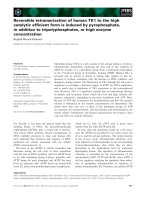
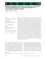
Fig. 1. (A) Illustration of a commercially available ÄKTA chromatography workstation with a dynamic mixer for preparation of a binary gradient from two pre-prepared
buffers solutions A and B. (B) Illustration of the adapted system with the in situ device for in-line conditioning using a single dual piston pump. The device is directly
connected to the dual pump of the ÄKTA workstation via a short tubular reactor.
column additional imidazole was fed into the beaker to reach a
target concentration of 500 mM imidazole.
3. Results and discussion
The concept of using solids directly to generate buffers and gradients on demand requires a device for continuously feeding solid
buffer components. Screw conveyer devices have been described
in the literature and are available for larger scale operation, but
unfortunately no miniaturized system for the slow solid feeding
rates necessary for lab-scale operation area was available. To circumvent this limitation, we used the now readily available additive manufacturing and designed a miniatures screw conveyor system, adapted for 3D printability and capable of delivering a very
small continuous feed of solid components. The system consists of
a screw conveyor and a feeding hopper as well as a mounting plate
and connection to the driving stepper motor for the screw conveyor. The device was mounted with screws and connected to a
stepper motor. The feeding of the screw conveyor was controlled
by adjusting the motion of the stepper motor. Solid buffer species
were introduced at the top of the screw conveyor to ensure a constant supply. The stepper motor was controlled through a simple
custom build python script (Fig. 2).
As the system was designed from scratch and no prior knowledge was available for such small screw conveyer systems and the
continuous transport of solids, a number of experiments to test
the device for accuracy, precision and stability with and without
connection to a chromatographic system and with several different
buffer components were performed.
3.1. Precision, accuracy and stability
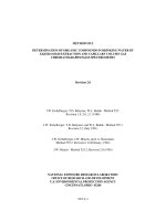
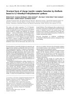
Fig. 2. The 3D design of the developed device for in situ preparation from crystals
or solids (1) with the Top (2), front (3) and side view (4).
Precision and accuracy of solid dosing was evaluated by weight
at different feeding speeds with sodium chloride, tris, sodium acetate, sodium citrate monohydrate, PEG60 0 0 and imidazole all in
crystal form. The speed of the feeder was varied between 20-120
rpm. For sodium chloride, the range was increased from 1-120 rpm
for the evaluation of long-term dosing. The actual feeding range in
terms of g.min−1 differed between the tested chemicals. The range
of the dosing rate was therefore dependent on the kind of solid,
presumably due to different particle size, particle roughness and
other physical properties, and the speed of the feeder needs to be
adjusted to the kind of crystals to achieve the same gravimetric
3
D. Komuczki, N. Lingg, A. Jungbauer et al.
Journal of Chromatography A 1634 (2020) 461663
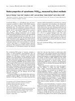
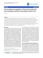
Fig. 3. (A) Dosing of five different buffering agents at various motor speeds (n=5). Colored points represent repeated dosing runs of sodium chloride (n=50) at three different
motor speeds. (B) Dosing profile of sodium chloride at three different motor speeds. If error bars are not shown then the error bars are smaller than the symbol.
feeding rate. Fig. 3 – (A) shows that for all components except imidazole the standard deviation was below 5% for all tested feeder
speeds (Table S1). Furthermore, we noticed that the dosing rate
in grams per revolution was highly dependent on the hygroscopic
characteristics and the resulting bridging formation in the hopper,
limiting the amount of crystal that is picked up by the screw conveyer itself. This is a well-known phenomenon in bulk and solid
handling which is caused by the geometry of the hopper and is
more pronounced in miniaturized systems. This led to difficulties to perform calibration curves for imidazole and sodium citrate
monohydrate. The recording of a calibration curve for imidazole
was therefore unfortunately not accurate enough to provide reliable enough feeding rates for the purpose of gradient generation
for chromatography in this miniaturized scale (data not shown). To
circumvent this limitation, we implemented a closed loop control
into the python script controlling the feeder to automatically readjust the screw conveyer speed during runtime by measuring the
weight of the hopper and feeder system. For sodium citrate monohydrate regular manual tapping of the hopper resolved the issue
of bridging formation and accurate and stable feeding rates were
achieved (Fig. 3 – A). To avoid such issues on larger scale, multiple
ways have been described in the literature ranging from specific
hopper geometries, additional mixing in the hopper to manual removal of any bridging [18,19]. As this work concentrates on the
application of the device for chromatography and not the hopper
design, we opted for manual removal of bridging when necessary
during runtime. However, we are certain that this shortcoming
for hygroscopic compounds can be solved by either device scale
up, hopper design or controlling environmental conditions as well
as additives [19,20]. Here, we saw significant differences of feeding rates for the investigated buffer components and we recommend investigating the dosing accuracy in dependence of the environmental conditions such as ambient temperature, humidity and
moisture for each compound separately. While for Imidazole, an
additional control by weight is necessary, it was not necessary to
include additional control systems for any other compound. Since
the calibration experiments resulted in a comparable performance
throughout the various buffering agents, we tested the system on
dosing accuracy and precision of repeated batches (g.min−1 , n=50)
for three different motor speeds using sodium chloride. As illustrated in Fig. 3 – (B) all batches conducted at various motor speeds
were in a ± 5% range of the initial target dosing rate. Finally, to
prove long term stability we performed a 24 h dosing at a very
low dosing rate of 0.05 g.min−1 to evaluate the stability of the system using sodium chloride and showed the stability of solid feed
flow (Figure – S1). As shown in Figure S1 a linear regression was
performed over the duration of the feeding and using a confidence
band of 95%. The standard error is very small (<5%) and over a
duration of 24h was comparable to the shorter dosing times performed prior. Therefore, we can conclude that the current design
offers precise and accurate performance in short term and long
term and is therefore suitable for gradient generation for individual chromatography runs as well as continuous long-term operation. Undoubtedly, there is still a need to further research on the
design of the device for having a closed system which is an inevitable requirement for an industrial application but it would be
out the scope of the proof of concept. Besides, that already existing
equipment such as twin screw conveyors are commercially available in closed fashion, thus, minimizing the risk of contamination
while allowing an adequate dust control.
3.2. Salt gradient elution
In order to demonstrate the application of the in-situ buffer
preparation directly from solid buffer components we have performed a small-scale chromatography. A binary protein mixture
4
D. Komuczki, N. Lingg, A. Jungbauer et al.
Journal of Chromatography A 1634 (2020) 461663
Table 1
Difference in elution conductivity between the in situ gradient formation by
direct feeding of buffer components and conventional preparation of buffers
for a 1 mL and 10 mL column. n.d. = not done.
Gradient length
Protein and column volume
Lysozyme (1 mL)
Cytochrome c (1 mL)
Lysozyme (10 mL)
Cytochrome c (10 mL)
5CV
Difference in %
1.22 %
1.19 %
0.30 %
4.53 %
10CV
20CV
2.16 %
0.92 %
n.d.
n.d.
3.93 %
1.92 %
n.d.
n.d.
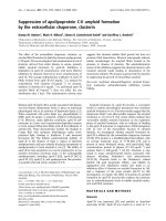
cient of variation of 1.3% (Elution conductivity at peak maximum
is 31.9 ± 0.41 mS.cm−1 ). We also measured the osmolality at the
end of the gradient and observed a coefficient of variation (947
± 18.2 mOsm.kg−1 ) of 1.9 %. For comparison we also performed a
conventional run using two pre-prepared buffers, and the gradient
generation by pumps and in-line mixer which resulted in a final
osmolality of 957 ± 1.2 mOsm.kg−1 .
Then we tested the device to perform gradients with different
lengths (5, 10 and 20 CVs) in 1 mL and 10 mL columns. The feeding rate was adjusted to the length of the gradient and the column
volume. The salt gradients generated by the two systems pumps of
the ÄKTA and the build-in mixer differed slightly at the beginning
of the gradient (Fig. 5). The linearity of the gradient produced by
the in-situ mixing from solid buffer components is comparable to
the conventional buffer preparation (Fig. 5). The slightly different
retention volumes of the eluted peaks are explained by the slightly
different slopes of the gradients. The difference in retention volumes is extremely small (Table 1) and vanished when the feeding
rate is adjusted.
The slight differences for both systems were addressed by recalibrating the solid feeding system before we scaled the method
from 1 mL (Fig. 5 – A, C, D) columns to 10 mL columns leading to
a much closer match between the two systems (Fig. 5 - B).
Fig. 4. Salt gradients generated by the in-situ preparation method directly from
solid buffer components for the separation of lysozyme and cytochrome c. UV absorbance was monitored at 280 nm and conductivity by the built-in monitors of
the ÄKTA workstation (n=5).
consisting of cytochrome c and lysozyme was separated on a 1
mL cation exchanger by a linear gradient. The tested solid feeder
was mounted on top of a small dynamic mixer (Fig. 1 - B) connected to an ÄKTA Pure chromatography workstation. After sample application, a gradient elution was performed by adding salt in
crystal form continuously to a liquid to achieve a gradient length
of 10 CV. For evaluating the capability of the device to perform
stable and linear gradients we repeated the gradient five consecutive times and evaluated the stability based on the elution peaks
of lysozyme and cytochrome c, conductivity as well as final osmolality (Fig. 4). The formation of the gradient by our method is
highly reproducible. This can be shown by the average and standard deviation of the conductivities at peak maximum. For elution of cytochrome c the average conductivity at peak maximum
measured at 405 nm was 16.3 ± 0.29 mS.cm−1 ; measured at 280
nm 16.4 ± 0.35 mS.cm−1 . This yields in a coefficient of variation
of 1.7 and 1.8% respectively. For lysozyme we obtained a coeffi-
Fig. 5. Salt elution gradients of different length for the separation of lysozyme and cytochrome c at 280 at 405 nm absorbance at 1 mL (A, C and D) and 10 mL CV (B) using
the ÄKTA (orange) and the device for in situ preparation from solid buffer components (blue), respectively.
5
D. Komuczki, N. Lingg, A. Jungbauer et al.
Journal of Chromatography A 1634 (2020) 461663
ported by the final osmolality of the equilibration (674.0 ± 3.28
mOsm.kg−1 device for in situ formation from solid buffer components vs. 670.50 ± 14.41 mOsm.kg−1 ÄKTA) and elution buffer
(1160 ± 19.55 mOsm.kg−1 device for in situ formation from solid
buffer components vs. 1190.52 ± 1.70 mOsm.kg−1 ), respectively.
Since imidazole can be readily measured by UV absorbance, comparisons without protein solution were performed (Fig. 6 - B). A
comparable performance of the in-situ gradient formation could be
observed.
4. Conclusion
In this study we showed a proof concept of in-situ gradient formation directly from solid buffer components for chromatographic
separations. The dosing accuracy is very high and precise operation
over a duration of 24 hours suits such a device for gradient elution.
By the direct dissolution of buffering agents at the point of use, we
can avoid the necessity of the preparation of stock solutions and
intermediate hold tanks and thus reduce the facility footprint of
chromatographic unit operations significantly. We also think that
with this device buffers can be prepared on demand and therefore
process materials can be saved. This will not only contribute to
better process efficiency but also to sustainability. Especially, considering the amounts of buffer that are prepared in excess to simply avoid supply shortfall. The implementation of a system for the
direct in-line dissolution of buffering agents offers a new level of
modularity and thus flexibility not achievable by in-line dilution or
in-line conditioning.
Funding Sources
Fig. 6. (A) Step elution gradients of imidazole performed by the ÄKTA (orange)
and the device for in situ preparation from solid buffer components (blue) fed
by weight. (B) Elution profile of imidazole performed by the ÄKTA and by in situ
preparation from solid buffer components in unloaded column conditions at 240
nm absorbance. Dashed lines (orange, blue, grey) illustrate absorbance at (A) 488
nm and (B) 240 nm as well as the concentration profile of the elution buffer (grey).
The work was supported by the A4B project funded by
the Horizon 2020 Marie Sklodowska-Curie Action ITN 2017 of
the European Commission (H2020-MSCA-ITN-2017. Grant number:
765502). Nico Lingg and Peter Satzer received support from the
Austrian Centre of Industrial Biotechnology, Vienna which was supported by the Federal Ministry of Science, Research, and Economy
(BMWFW), the Federal Ministry of Traffic, Innovation, and Technology (BMVIT), the Styrian Business Promotion Agency SFG, the Standortagentur Tirol, the Government of Lower Austria, and Business
Agency Vienna through the COMET Funding Program managed by
the Austrian Research Promotion Agency FFG.
The chromatograms are very similar irrespective of the method
which is used for preparation of the buffers. The difference in
the gradient shape are explained by the different dead volume,
which is mainly determined by the dynamic mixer in conventional
chromatography systems and by the static mixer in our system. A
feedback control loop would help to generate theoretical gradient
shapes [9,11,21].
Author_contribution
3.3. Imidazole step elution
Daniel Komuzcki: constructed the equipment, conducted the
experiments, drafted the manuscript
Nico Lingg: was responsible for gradient design, reviewed and
edited the manuscript
Alois Jungbauer: Wrote the research proposal, drafted the
manuscript, and helped with interpretation of the data
Peter Satzer: Wrote the control algorithm, help to design the
equipment, converted the design into a 3D print
Imidazole is a very common buffer in metal chelate chromatography and therefore we selected such a buffer as model to demonstrate our in-situ gradient formation system. Besides linear gradients, we developed a methodology for the device to generate
a step gradient. Once again, the device was mounted on a vessel filled with base buffer which was used for equilibration and
sample application to the immobilized metal affinity chromatography column. After the equilibration a His-Tag GFP solution was
loaded on the column by pulse injection. To generate the step gradient, imidazole was fed with maximum speed (200 rpm) into the
buffer reservoir to reach 500 mM imidazole as fast as possible. The
feeding was done by weight to ensure a steep gradient for elution
due to the aforementioned hygroscopicity of imidazole. The ÄKTA
was on pause over the duration of the feeding (10 minutes). Nevertheless, it is intriguing that the step gradient performed by the
ÄKTA using the in-line mixer and the device for in situ preparation
from solid buffer components approach resulted in almost identical chromatograms (Fig. 6 - A). These findings are further sup-
Declaration of Competing Interest
The authors declare that they have no known competing financial interests or personal relationships that could have appeared to
influence the work reported in this paper.
Supplementary materials
Supplementary material associated with this article can be
found, in the online version, at doi:10.1016/j.chroma.2020.461663.
6
D. Komuczki, N. Lingg, A. Jungbauer et al.
Journal of Chromatography A 1634 (2020) 461663
References
[11] A. Tsai, E. Carredano, K. Busson, Deploying Automated Buffer Production for
cGMP Use: Points to Consider, BioProcessing Journal 18 (Vi) (2019) 1–13,
doi:10.12665/j18oa-tsai.
[12] B. Mothes, ACCELERATED SEAMLESS ANTIBODY PURIFICATION: SIMPLICITY IS
KEY, in: U. Gottschalk (Ed.), Process Scale Purification of Antibodies, 2017,
pp. 431–443, doi:10.1002/9781119126942.ch20.
[13] B. Mothes, J. Pezzini, K. Schröder-Tittmann, Accelerated, Seamless Antibody Purification Process Intensification with Continuous Disposable Technology, 2016.
[14] J.Y. Lee, K. Dang, A. Liu, B.M. Alba, Automated buffer preparation using quaternary valve in fast performance liquid chromatography for protein purification
from a cell membrane, Journal of Chromatography B: Analytical Technologies
in the Biomedical and Life Sciences 1136 (November 2019) (2020) 121849 121849, doi:10.1016/j.jchromb.2019.121849.
[15] D. Winters, C. Chu, K. Walker, Automated two-step chromatography using an
ÄKTA equipped with in-line dilution capability, Journal of Chromatography A
1424 (2015) 51–58, doi:10.1016/j.chroma.2015.10.092.
[16] N. Andersson, A. Lövgren, M. Olofsson, A. Sellberg, B. Nilsson, The orbit controller, Department of Chemical Engineering, Lund University, Lund, 2016.
[17] J. Gomis-Fons, A. Löfgren, N. Andersson, B. Nilsson, L. Berghard, S. Wood, Integration of a complete downstream process for the automated lab-scale production of a recombinant protein, Journal of Biotechnology 301 (December 2018)
(2019) 45–51, doi:10.1016/j.jbiotec.2019.05.013.
[18] A.W. Jenike, Storage and flow of solids, University of Utah, Salt Lake City, 1964.
[19] D. McGlinchey, Bulk Solids Handling: Equipment Selection and Operation,
2008.
[20] M.P. Mullarney, L.E. Beach, R.N. Davé, B.A. Langdon, M. Polizzi, D.O. Blackwood,
Applying dry powder coatings to pharmaceutical powders using a comil for
improving powder flow and bulk density, Powder Technology 212 (3) (2011)
397–402, doi:10.1016/j.powtec.2011.06.008.
[21] O. Kaltenbrunner, A. Jungbauer, Simple model for blending aqueous salt
buffers: Application to preparative chromatography, Journal of Chromatography A 769 (1) (1997) 37–48, doi:10.1016/S0 021-9673(97)0 0161-1.
[1] K. Gibson, P. Vengsarkar, P. De Vilmorin, C. Jones, A. Sinclair, S. Attig, C. Carlson, H. Ardeshna, C. Mason, R. Jones, J. Johnson, N. Frau, D. Ring, D. Wiseman,
An Economic Evaluation of Buffer Preparation Philosophies for the Biopharmaceutical Industry, 2019.
[2] R. Hedley, Supply Chain Management in the Drug Industry Delivering Patient
Value for Pharmaceuticals and Biologics 2011.
[3] O. Kaltenbrunner, A. Jungbauer, Simple model for blending aqueous salt buffers
Application to preparative chromatography, Journal of Chromatography A 769
(1) (1997) 37–48, doi:10.1016/S0 021-9673(97)0 0161-1.
[4] G. Carta, A. Jungbauer, Protein Chromatography: Process Development and
Scale-Up, 2010. 10.1002/9783527630158.
[5] D. Iurashev, S. Schweiger, A. Jungbauer, J. Zanghellini, Dissecting peak broadening in chromatography columns under non-binding conditions, Journal of
Chromatography A 1599 (2019) 55–65, doi:10.1016/j.chroma.2019.03.065.
[6] O. Kaltenbrunner, A. Jungbauer, S. Yamamoto, Prediction of the preparative
chromatography performance with a very small column, Journal of Chromatography A 760 (1) (1997) 41–53, doi:10.1016/S0 021-9673(96)0 0689-9.
[7] A.L. Cataldo, D. Burgstaller, G. Hribar, A. Jungbauer, P. Satzer, Economics and
ecology: Modelling of continuous primary recovery and capture scenarios for
recombinant antibody production, Journal of Biotechnology 308 (December
2019) (2020) 87–95, doi:10.1016/j.jbiotec.2019.12.001.
[8] L. Arnold, K. Lee, J. Rucker-Pezzini, J.H. Lee, Implementation of Fully Integrated
Continuous Antibody Processing: Effects on Productivity and COGm, Biotechnology Journal 14 (2) (2019) 1–10, doi:10.10 02/biot.20180 0 061.
[9] E.N. Carredano, R. Nordberg, S. Westin, K. Busson, T.M. Karlsson, T.S. Blank,
H. Sandegren, G. Jagschies, Simplification of Buffer Formulation and Improvement of Buffer Control with In-Line Conditioning (IC), Elsevier Ltd., 2018,
doi:10.1016/B978- 0- 08- 100623- 8.00027- X.
[10] A. Jungbauer, N. Walch, Buffer recycling in downstream processing of biologics, Current Opinion in Chemical Engineering 10 (Complete) (2015) 1–7,
doi:10.1016/j.coche.2015.06.001.
7