Tài liệu thiết kế khuôn mẫu
Bạn đang xem bản rút gọn của tài liệu. Xem và tải ngay bản đầy đủ của tài liệu tại đây (2.28 MB, 43 trang )
1
Mold.ppt
C
C
ORE
ORE
T
T
ECH
ECH
S
S
YSTEM
YSTEM
Mold Design
Mold Design
Fundamentals
Fundamentals
2
C
C
OR
E
OR
E
T
T
ECH
ECH
S
S
YSTE
M
YSTE
M
Mold.ppt
Basic Tasks of a Mold
Basic Tasks of a Mold
q Accomodation and Distribution of the Melt
q Shaping of the Molded Part
q Cooling/Heating and Solidification of the Melt
q Ejection (Demolding) of the Molding
q Mechanical Functions
) Accomodation of forces
) Transmission of motion
) Guidance of the mold components
The mold is probably the most important element of a molding machine. It is a
arrangement, in one assembly, of one (or a number of) hollow cavity spaces built
to the shape of the desired product, with the purpose of producing large numbers
of plastic parts. Thus the primary purpose of the injection mold is to determine
the final shape of the molded part (shaping function).
In addition to give the final shape of the molding, the mold performs several
other tasks. It conducts the hot melt from the heating cylinder in the injection
molding machine and distributes the melt to the cavity (or cavities), vents the
entrapped air or gas, cools the part until it is ejectable, and ejects the part without
leaving marks or causing damage.
The secondary tasks of a mold derived from these primary tasks include several
mechanical functions such as accommodation of forces, transmission of motion,
guidance and alignment of the mold components.
The mold design, construction, the craftsmanship largely determine the quality
of the part and it manufacturing cost.
3
C
C
OR
E
OR
E
T
T
ECH
ECH
S
S
YSTE
M
YSTE
M
Mold.ppt
Functional Systems of the Injection
Functional Systems of the Injection
Molds
Molds
q Melt Delivery System: Sprue/Runner/Gate
q Cavity (with Venting)
q Tempering/Heat Exchange System
q Ejection System
q Guiding and Locating System
q Machine Platen Mounts
q Force Supplier
q Motion Transmission System
An injection mold is composed of several functional units. Each unit performs
one or several task of the mold.
The melt delivery system or runner system performs the task of receiving and
distribution of the melt. The runner system is in fact a set of flow channels that
lead the melt into the cavities.
Forming/shaping the molten material into the final shape of the part is the job of
the cavity. During the filling and packing/holding stages, melt is forced by
injection/holding pressure to completely fill the cavity (or cavities).
Mold tempering or heat exchange system is used to control the mold
temperature, cool down the molten melt (or,if thermosets or elastomer are used,
heat the melt and cross-link the material) uniformly, solidify the molding to an
ejectable state. Mold tempering system design has direct impact to the production
cycle time and the quality of the molded part.
Ejector system is utilized to open the mold and remove the molded part from the
cavity. Mold mounting, alignment, and guiding are accomplished by the
guidance/ locating system and machine platen mounts. Other auxiliary units such
as force supplier and movement transmission unit are essential to accomplish the
functions of an injection mold.
4
C
C
OR
E
OR
E
T
T
ECH
ECH
S
S
YSTE
M
YSTE
M
Mold.ppt
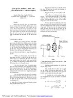
Structure of A Mold Unit
Structure of A Mold Unit
Sprue
Sprue
Primary Runner
Secondary Runner
/Sub-runner
Gate
Part
Cold-Slug Well
Cold-Slug Well
Sprue Ejector Pin
Sprue Bushing
Above figure shows the layout af a typical simple injection mold, which has
four identical cavities. Melt from the nozzle enters the mold via the spure, which
has a divergent taper to facilitate removal when demolding.
Opposite the sprue is a cold slug well, which serves both to accept the first
relatively cold portion of the injected material, and to allow a re-entrant shape on
the end of an ejector pin to grip the sprue when the mold opens.
The melt flows along a system of runners leading to the mold cavities. In
general, for a single cavity mold, only the sprue or primary runner appears in the
mold; whereas for a multicavity mold, secondary runners or subrunners are
needed to distribute the melt into each cavity.
The gates at the entries to the cavities are very narrow passages in at least one
directions, so that the molded part can be readily detachable from the runners
after removal from the mold.
Sometimes additional cold slug wells are added in the end of primary runners to
trap the cold slug during the filling stage.
The mold is aligned with the nozzle on the injection cylinder by means of the
locating ring surrounds the sprue bushing.
5
C
C
ORE
ORE
T
T
ECH
ECH
S
S
YSTE
M
YSTE
M
Mold.ppt
Mold Design Issues
Mold Design Issues
mold base
cooling channel/lines
runner (mainfold) system
gate
cavity
q
Mold Design
) No.Cavity
) Cavity Layout
) Runner System Design
) Gating Scheme
) No.Gate
) Gating Location
) Mechanical/Mechanism
Consideration
q Cooling System Design
) Cooling Channel Layout
) Special Design
The primary tasks of an injection mold include the accomodation and
distribution of the melt, the shaping and cooling/heating of the molding,
solidification of the melt, as well as ejection of the molded part. Besides, a mold
has to provide mechaincal functions such as accomodation of forces,
transmission of motion, and guidance of mold components.
Hence the primary functional systems of a injection mold include the melt
delivery system ( sprue/runner/gate ), cavity (single-cavity or multicavity),
ejection system, guiding and locating system, as well as mold temperature
control unit (cooling system).
From the view point of mold design, we have to evaluate the suitable size and
layout of runner system and cavity, number of cavity, cooling system, etc.
We will propose a few examples to illustrate how these design parameters
influence the productivity and quality of the moldings.
6
C
C
OR
E
OR
E
T
T
ECH
ECH
S
S
YSTE
M
YSTE
M
Mold.ppt
Determine Number of Cavities
Determine Number of Cavities
q Single Cavity vs. Multicavity Mold
) Productivity and complecity consideration
q Determination of Number of Mold Cavities
) Number of moldings required and period of delivery
) Quality control requirements (dimensional tolerance,etc.)
) Cost of the moldings
) Shape, dimensions, and complexity of the molding (position of
parting line and mold release)
) Size and type of the injection molding machine machine (shot
capacity, plasticizing capacity, mold release )
) Plastics used (gating scheme and gate location)
) Cycle time (increase in recovery time of plasticating unit,
injection time, pressure drop, and mold opening time)
The multiple mold cavities can produce several article at the same time and
hence has a higher output speeds and improved productivity. However, the
greater complexity of the mold also increases significantly the manufacturing
cost. The problems arising from a multicavity mold includes cavity layout, flow
balance, balanced cooling channels layout, etc.
Theoretically, for the same product, cycle time do not increase prorate with the
number of cavities because th cooling time does not change. However, one often
find that cycle time will increase as the number of cavities increases, for the
following reasons:
-Increase in recovery time of plasticating unit for the next shot and injection
time because the total shot volume is increased. These increases in time are
significant for large shots.
-Increase in pressure drop becaused of the increased flow length from sprue,
through runner system, to each cavity. The pressure drop can be a determining
factor in the evaluation of numbers of cavity.
-Increase in mold opening time because of the increased complexity.
Both the technical and economic criteria have to be considered in determining
the number of mold cavity, such as the numbers of moldings required, the cost
and time of mold construction, the complexity of the molding, cycle time, quality
requirements and the plasticating capacity of the available machine equipment,
etc.
7
C
C
ORE
ORE
T
T
ECH
ECH
S
S
YSTE
M
YSTE
M
Mold.ppt
Cavity Layout
Cavity Layout
Layout in Series
Circular Layout
X-style layout
H-style bridge
(branching) layout
When the number of parts produced in each cycle exceeds one, a multicavity
mold have to be used. Many cavity layouts can be adopted in the production.
For example, layout in series has the advantage that there is no space restriction
for each cavity; however, the unequal flow lengths to individual cavities may
lead to unbalanced flow and differential part weights in each cavity.
Circular layout has the advantage of equal flow length and uniform part
quality; however, only limited number of cavities can be accomodated by this
layout.
H-style layout and X-style layout belongs to the so-called symmetrical layout.
They are good in flow balance. Their disadvantage is that more larger runner
volume and much scrap will be generated. Hot runner system can be adopted to
conquer this drawback.
Layout of cavities not only influence the filling pattern and extent of pressure
packing, but also determines the equilibrium of injection force and clamp force
during the molding cycle.
8
C
C
OR
E
OR
E
T
T
ECH
ECH
S
S
YSTE
M
YSTE
M
Mold.ppt
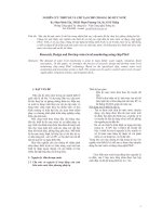
Design of Runner System
Design of Runner System
Piston or
Screw
Screw Chamber
(Reservoir)
Heating Element
Nozzle
Runner
Gate
Sprue
Cavity
Mold Unit
q Runner System
) Sprue
) Runner
(Primary/Secondary)
) Gate
q Goal:
) Accommodates the molten plastics material coming from the screw
chamber and guides/distributes it into the mold cavity
) Raises the melt temperature to the proper processing range by viscous
(frictional) heating while the melt is flowing through the runner
q
Design Consideration
) Quality (filling pattern ) & Economics (cycle time )
A runner system is composed of the sprue, the runner(s), and the gate(s) that
connecting the runner with the cavity.
The primary task of a runner is the delivery and distribution of melt from the
screw chamber into the mold cavity. The runner system must be designed in such
a way that the melt fills all cavities simultaneously and uniformly under uniform
pressure and temperature. This design criterion is referred to as the flow balance
of the runner system.
Melt temperature may be significantly increased as it passes througn the narrow
runner passage or gate due to friction effect. This viscous heating is important in
raising the melt temperature and reducing the flow resistance because of the
shear-thinning character of plastic material.
The runner system has significant impact on the part quality and the economics
of manufacture. Problems such as weld lines, pressure drop, material waste,
removability of moldings, etc.,are related to the design of runner system.
9
C
C
OR
E
OR
E
T
T
ECH
ECH
S
S
YSTE
M
YSTE
M
Mold.ppt
Common Runner Cross Sections
Common Runner Cross Sections
q Circular Runner
) Full Round Runner
q Parabolic Runner
) U-Type or Modified
Trapesoidal Runner
q Trapezoidal Runner
q Half Round Runner
q Rectangular Runner
There are several types of cross section can be adopted for a runner. The
selection of the runner cross section depends on its efficiency and ease or
difficulty of tooling.
Circular or full round cross section provides a maximum volume-to-surface
ratio and hence offers the least resistance to flow and least heat loss from the
runner. However, it requires a duplicate machining operation in the mold, since
two semi-circular sections have to be cut for both mold halves and aligned as the
mold is closed.
Parabolic or U-type runner represents a best approximation of circular runner,
although more heat losses and scrab produced (mass is 35% greater), it needs
simpler machining in one (movable) mold half only.
Trepezoidal runner is an alternative modification of circular runner, its
performance is similar to that of the parabolic runner. Trapezoidal runner is
often used in three-plate molds since sliding movements are required across the
parting-line runner face.
Half round and rectangular cross section may lead to larger flow resistance and
are unfavorable in the runner cross section.
Normally, full round or trapesoidal runners are adopted in most practical cases.
10
C
C
OR
E
OR
E
T
T
ECH
ECH
S
S
YSTE
M
YSTE
M
Mold.ppt
Considerations in Runner Design
Considerations in Runner Design
q Part Consideration
) Geometry, Volume, Wall Thickness
) Quality (Dimensional,Optical, Mechanical )
q Material Consideration
) Viscosity, Composition, Fillers,Softening Range, Softening
Temperature,Thermal Sensivity, Shrinkage, Freezing Time
q Machine Consideration
) Type of Clamping, Injection Pressure, Injection Rate
q Mold Consideration
) Way of Demolding, Temperature Control
Key factors affecting the design of a runner are summarized here.
In the aspect of part consideration, the geometric dimensions of the runner
should be such that flow restriction is at a minimum, that is, the runner should
convey melt rapidly and unrestricitly into the cavity in the shortest way and with
a minimum heat and pressure losses. The runner system should allow cavity
filling with a minimum numbers of weld line so that the mechanical and surface
properties of moldings can be improved. The runner should permit the
transmission of holding pressure during the packing/holding stage so that the
dimensional accuracy can be ensured.
In the aspect of material consideration, the flow character and the thermal
properties of material are related to the sizing of runner diameter and the runner
length. Long or small runner should be avoided for material with short flow
length (high viscosity). Runner should be properly sized to minimize material
waste while not cause significant pressure loss.
In the aspect of machine consideration, we should note the allowable injection
pressure, injection rate, type of clamping, etc.
The runner should be design so that demolding and removal from the molded is
easy. Location and number of runner ejectors should be considered in the mold
design phase.
11
C
C
ORE
ORE
T
T
ECH
ECH
S
S
YSTE
M
YSTE
M
Mold.ppt
Flow Balance in the Runner Design
Flow Balance in the Runner Design
q Flow Balance in Multi-Cavity Molds:
) Increase in recovery time of plasticating unit, injection time,
pressure drop, and mold opening time
PLAY412
Consider the runner system design in the multicavity mold case.
In a symmetric, naturally balanced cavity layout, all flow lengths from the
sprue to each cavity are of the same length. In this ideal case the plastic melt will
fill all cavities simultaneously under the same pressure and temperature
conditions. The molded part in each cavity has the same weight and final
properties.
Unfortunately not all runners can be naturally balanced, especially for large
parts where multiple gating may be needed to produce a proper part. Moreover,
the natural flow balance is difficult for molds with a large number of cavities
and is even impossible for the so-called family mold (combination mold) where
each of the cavities is of different size and forms one component part of the
assembled finished product.
In these cases we have to balance the flow artifically. Balancing ensures
virtually equal flow of plastic through each gate of a multicavity mold, and/or
through each gate (if there is more than one) into each cavity. The melt should
arrive at all gates/cavities at the same time and with the same properties so that
all molded parts have uniform characteristics. This type of runner system is
called the artifically balanced runner systems.
On the other hand, even though the cavity layout is virtually balanced, the
desired balanced flow may not be achieved since the flow depends on the plastic
material used, the process condition setting, the accuracy of machining and the
finish inside the channel, temperature difference due to unbalanced
cooling/heating, , uneven venting, mold surface quality, etc.
12
C
C
ORE
ORE
T
T
ECH
ECH
S
S
YSTE
M
YSTE
M
Mold.ppt
Runner Design and Part Shrinkage
Runner Design and Part Shrinkage
Runner cross-sectional Area
Part Shrinkage
Runner Length
Part Shrinkage
The runner system design has a significant impact on the quality of moldings.
For example, the part shrinkage increases as the runner length is increased since
more pressure drop in the runner system and the melt is less packed within the
mold. In general, the runner length should be as short as possible in order to
reduce the pressure drop and amount of scrap. However, the runners must be of
adequate length to satisfy the other conditions such as flow balance
consideration, accommodation of cooling lines and ejector pins, etc.
The part shrinkage reduces as the runner cross section is increased since the
filling process is promoted and the effective holding pressure is higher. However,
increase the runner size also produces more scrap and material waste.
The size of the runner depends on the size of the part and its wall thickness, the
design of the mold and the type of plastic being processed. Plastics with low
viscosity (high melt flow index or long flow length) permit a longer or thinner
runner.
The runner cross section should be as small as possible but still compatible with
the melt flow requirement such as pressure drop consideration.
13
C
C
OR
E
OR
E
T
T
ECH
ECH
S
S
YSTE
M
YSTE
M
Mold.ppt
Design of Runner
Design of Runner
Plastic Materials Recommended
R
unn
e
r
D
i
am
e
t
e
r
s
A
B
S
,
S
A
N
0.187-0.375” (4.7-9.5mm)
Acetal
0.125-0.375” (3.1-9.5mm)
A
c
r
y
l
i
c
0.312-0.375” (7.5-9.5mm)
Butyrate
0.187-0.375” (4.7-9.5mm)
Cellulosics
0.187-0.375” (4.7-9.5mm)
Fluorocarbon
0.187-0.375” (4.7-9.5mm)
Ionomer
0.093-0.375” (2.3-9.5mm)
N
y
l
on
0.062-0.375” (1.5-9.5mm)
Polyamide
0.187-0.375” (4.7-9.5mm)
P
C
0.187-0.375”
(
4.7-9.5mm
)
Polyester
0.187-0.375” (4.7-9.5mm)
PE
0.062-0.375” (1.5-9.5mm)
PP
0.187-0.375” (4.7-9.5mm)
PPO
0.250-0.375” (6.3-9.5mm)
Po
l
y
s
u
l
f
on
e
0.250-0.375” (6.3-9.5mm)
PS
0.125-0.375” (3.1-9.5mm)
PU
0.250-0.313” (6.4-8.0mm)
PVC
0.125-0.375” (3.1-9.5mm)
For most thermoplastics, minimum recommended runner size=1.5mm (0.06”)
This table lists the recommended runner diameters for different thermo-plastics
in injection molding industry. For most thermoplastics, the minimum
recommended dimension of runner is 1.5mm (0.06”), too small the dimension
may lead to excessive presure drop and filling difficulty.
The recommended runner size also reveals the flow ability (processability) of
the plastic material. Plastics with low viscosity (high melt flow index or long
flow length) such as polyethylene (PE) permit a smaller runner. Larger runner
should be adopted for plastics that have shorter flow lengths (higher viscosity
values), such as polycarbonate (PC).
This table serves as an initial guess for runner sizing.
14
C
C
OR
E
OR
E
T
T
ECH
ECH
S
S
YSTE
M
YSTE
M
Mold.ppt
Design of Runner
Design of Runner
q Location and Number of Runner Ejectors
Stiffer Plastics
Ejector Pin
Softer/Flexible/Sticky
Plastics
Both the number and location of ejectors depend on the plastic being processed.
The stiffer the plastic is (at the moment of ejection), the fewer ejectors are
needed; also, the designer has higher degree of freedom to determine the ejector
locations. For example, the ejectors can be placed under the connecting runners
(bridge runners) .
For soft, flexible, or sticky plastics, more ejectors have to be adopted. Care must
be taken in the ejector location so that the part can be ejected without leaving
marks or causing damage. In general, more ejectors lead to an increase in the
comlexicity of mold and the cost of the hardware and of machining.
In the design phase of the runner system, one should consider the ease of
demolding and removal from the molded part. The runner system should provide
sufficient spacing for cavity in order to accommodate cooling lines and ejector
pins and leave adequate cross section to withstand the injection pressure force.
1
5
C
C
OR
E
OR
E
T
T
ECH
ECH
S
S
YSTE
M
YSTE
M
Mold.ppt
Runnerless Molding Technology
Runnerless Molding Technology
Moldings
Runner System:
•Scrap and material waste
•Pressure drop
q Runnerless Molding Technology:
) runners and sprues are kept a molten state during the processing
) runner systems are never actually ejected with the molded parts.
q Types of Runnerless Molding Technology:
) Insulated Runner System
) Heated/Hot Runner System
The conventional runner systemare referred to as cold runner systems since the
runners solidifies during the cooling phase of the injection molding cycle and is
ejected with the part. During the molding cycle the pressure drop increas as the
runner is cooled down gradually. Degating is required during mold opening (for
three-plate molds) or separately afterwards (for two-plate molds) and the runner
system is regarded as scrap. The runner material may be reground and recycled
again, but it may have some physical properties degraded from the original,
virgin material. For small products the mass of cold runners may be as much as
80% of the mass of the total shot.
On the other hand, the so-called runnerless molding technology has been
developed to circumvent the drawbacks encountered in the cold runner systems.
In these special mold designs the runners and sprues are kept a molten state
during the processing and are never actually ejected with the molded part. There
are no runners to be reground and recycled, thus, savings in material, labor,
and/or overhead are realized.
Typical examples of runnerless molding methods include insulated runners,
heated/hot runner systems.
1
6
C
C
OR
E
OR
E
T
T
ECH
ECH
S
S
YSTE
M
YSTE
M
Mold.ppt
Insulated Runner System
Insulated Runner System
Molten state melt
Solidified resin shell
Cooling Lines
Emergency
parting line
Parting line
q Oversized the runner diameter (15~30mm)
q Insulation effect of frozen skin shell
q Works for most olefinic resins(PE,PP ) and PS
In the insulated runner system, the runner diameter is oversized (say, 15~30mm)
in order to maintain the molten state of the material. The large diameter runner
allows an inner molten melt to pass through during the molding cycle because of
the insulation effect of frozen skin shell surrounding the melt core.
The insulation runner system has the advantage of extremely simple
construction, low cost tooling, and high efficiency, provided the system can be
left running undisturbed for long periods. This design is suitable for most olefinic
plastics (such as polyethylene (PE), polypropylene (PP) ) and polystryene (PS).
The disadvantages of the insulated runner system includes:
- it requires fast cycle to maintain molten state within runner (at least 5
shots/min).
- it requires long start-up periods (15-25min) to stabilize the runner temperature
(up to 150
o
C)
- it needs a long color change time
- it needs very accurate gate temperature control in order to have a satisfactory
production rate.
- Additional emergency parting line is required to facilitate the removal of the
frozen runner in the case of prolonged delay in the cycle time.
1
7
C
C
OR
E
OR
E
T
T
ECH
ECH
S
S
YSTE
M
YSTE
M
Mold.ppt
Internally Heated Hot Runner
Internally Heated Hot Runner
System
System
q Material is heated by the heating element in the center of the runner
q Annular gap for melt flow
Heater Cartridge
Heated Probe
(Torpedoe)
Part
Melt
Tempertature Profile
Vlocity Profile
In the internally heated hot runner system, the material is heated and kept at a
molten state by the heated probe (torpedoe) in the center of the runner. The melt
is allowed to flow in the cross section of the annular gap of the runner.
The advantages of the internally heated hot runner systems include:
-Less heat loss and lower heating power required since the thermal insulation of
polymer melt
-Less mold components mis-matching problem arising from thermal expansion
-Inexpensive (as compared with the external heated runner system)
-Little space required.
The disadvantages of this design include:
-Higher shear rate and pressure drop since the restricted flow area
-Sophicated heat control required (temperature profile exists in the cross
section of the annular gap of the runner).
18
C
C
OR
E
OR
E
T
T
ECH
ECH
S
S
YSTE
M
YSTE
M
Mold.ppt
Externally Heated Hot Runner
Externally Heated Hot Runner
System
System
q Material is heated by the cartridge-heating manifold in
the housing of the runner
q Circular cross section for melt flow
Cooling Lines
Heater Cartridge
Heated Manifold
Part
Air gap insulation
Insulation Blocks
Hot Runner
Vlocity Profile:
plug-like flow
Temperature Profile:
constant temperature profile
In the externally heated hot runner system the material is heated by the
cartridge-heating manifold in the housing of the runner. Thus a plug-like flow
profile and an approximately constant temperature profile across over the circular
flow area is developed. Thus the flow resistance is smaller than that of the
internally heated system.
The advantages of this design are:
-More uniform temperature distribution.
-Better temperature control
-Lower melt stresses and pressure drop
-Color/material changes easily
The disadvantages of the externally heated hot runner system include:
-More complicated design
-More Expensive
-Significant thermal-expansion-induced mis-match problems for various mold
components.
19
C
C
OR
E
OR
E
T
T
ECH
ECH
S
S
YSTE
M
YSTE
M
Mold.ppt
Design of Gate
Design of Gate
Generalities
•ease of demolding
•ease of degating
•weld lines
•distortion
•molding defects
•cost
Part Design
•geometry
•wall thickness
•direction of mechanical
loading
•quality demands
(dimensions,cosmetics,
mechanics )
•Flow length
Plastic
Material
•viscosity (MFI)
•processing temperature
•flow characteristic
•fillers
•shrinkage behavior
Then gate provides the connection between the runner and the mold cavity. It
must permit enough material to flow into the mold to fill out the cavity, raises
melt temperature by viscous (frictional) heating, and freezes-off when the
holding stage is over. It should be smaller in the cross section so that it can be
easily separated from the molded part (degated).
The type of the gate and its size and location in the mold strongly affect the
molding property and the quality of the molded part. The factors which
determine the gate design is summarized here briefly.
General speaking, the gate should be small, simple to demold and easily
separated from the part. The gate should be connected to the molding in such a
manner that the latter is not distorted (the molding tends to deform concave to the
feed ) and does not exhibit blemishes. Cost of tooling is also a consideration
factor. The location of the gate must be such that weld lines are avoided or
shifted to a less critical position. Molding defects such as jetting, burning,
thermal degradation, short shot, etc. should be avoided in the production.
Gating scheme and location of gates are crucial to the quality of the molding.
Filling pattern and cavity pressure profile are closely related to the final
properties of molded parts, such an mechanical properties, cosmetics (surface
properties), dimensional accuracy. A gate should provide appropriate filling
pattern and viscous heating effect, permit effective packing and holding of the
material within the mold. These criteria depend on both part design as well as
physical properties of the plastic material.
20
C
C
ORE
ORE
T
T
ECH
ECH
S
S
YSTE
M
YSTE
M
Mold.ppt
Gating Scheme
Gating Scheme
Direct/Sprue Gate
Side/Edge Gate
‧
‧
‧
‧
‧
‧
‧
‧
‧
‧
‧
‧
‧
‧
‧
‧
‧
‧
‧
‧
‧
‧
‧
‧
‧
‧
‧
‧
‧
‧
‧
‧
‧
‧
‧
‧
‧
‧
‧
‧
‧
‧
‧
‧
‧
‧
‧
‧
‧
‧
Pin Gate
There are several gate type can be adopted in the mold design, and each has its
own advantage for application.
The direct gate or sprue gate feeds material directly into the cavity. It is used
for temperature-sensitive or high viscosity materials, and is suitable for
producing part with heavy sections. The direct gate can be applied in high quality
part because it allows effective holding (minimum pressure loss) and exact
dimensions can be obtained. However, it is suitable only for single-cavity molds.
Visible gate mark and the high stress concentration around the gate area are the
disadvantges.
The side gate or edge gate is the standard gate for injection molding. It is used
wherever the product can be or must be gated from the parting line and where
self-degating is not required or practical. It is carried out at the side of the part
and is easy to construct and degate.
The pin gate or pinpoint gate is a kind of restricted gates that are usually
circular in cross section and for most thermoplastics do not exceed 1.5mm (0.06
in.) in diameter. It is generally used in three-plate molds (with automatic gate
removal) and hot runner construction. It provides rapid freeze-off and easy
degating of the runner from the gate. Flexibility in gate location is another
advantage of the pin gate. It can easily provide multiple gating to a cavity for
thin-walled parts. Viscous heating as the melt passing through the restricted
pinpoint gate raises melt temperature and improves the filling process since the
melt viscosity is lowered. Higher pressure drop is a drawback.
21
C
C
OR
E
OR
E
T
T
ECH
ECH
S
S
YSTE
M
YSTE
M
Mold.ppt
Gating Scheme
Gating Scheme
Fan Gate
Film Gate
Tab Gate
Disc Gate
The fan or fin gate is a fanned out variation of the edge gate. It is used for large
flat parts (say,over 8cm x 8cm or 3 in x 3 in) or when there is a special reason
such as elimination of weld lines. when the danger of part warpage and
dimensional change exists, the fan gate is often adopted.
The film gate or flash gate involves extending the fan gate over the full length
of the part but keeping it very thin. It is used for flat molded part in the situation
that the orientation of flow pattern in one direction is required, this is important
in the applications of optical parts. It has the advantages that there is no weld
line, reduced warpage and improved part dimensional stability. However,
postoperation for gate removal is required for this type of gate.
The tab gate is used in cases where it is desirable to transfer the stress generated
in the gate to an auxiliary tab, which is removed in a postmolding operation. The
tab gate is capable of preventing the jetting problem during the filling stage. Flat
and thin parts require this type of gate.
The disc gate or its variation, the diaphragm gate, has a conical manifold. It is
used for rotationally symmetrical parts (hollow tubes) with core mounted at just
one half of the mold. The advantage of using this gate system is that there are no
weld lines, and concentricity of the molded part is ensured. This is a important
dimensional requirement for pipe fittings. The cone or diagram region eliminates
stress concentration around the gate since the whole area is removed, but the
postoperation is necessary and more difficulty.
22
C
C
OR
E
OR
E
T
T
ECH
ECH
S
S
YSTE
M
YSTE
M
Mold.ppt
Gating Scheme
Gating Scheme
Ring Gate
Submarine/Tunnel Gate
The ring gate accomplishes the same purpose as gating internally in a hollow
tube, but from the outside. In the ring gate the melt reaches an annular channel
manifold next to the sprue. The gate has a small cross section and acts as a
throttle. Therefore the annular channel fills before melt begins to fill the cavity. It
is adopted in the case that the core cannot be mounted on just one side of the
mold such as in the case of disc gating. The ring gate is used to produce sleeve-
like parts with core mounted at both sides of the mold.The advantages of this
gating scheme include: uniform wall thickness around circumference can be
obtained, applicable for long cylindrical part, as well as easy production.
However, final finishing of molded part is necessary and sometimes slight weld
line may appear.
The submarine or tunnel gate is used mainly for small parts in multicavity mold
where it is possible to locate the gate laterally. This gate is automatically degated
as soon as the mold opens, this is the primary advantage of this gate system.
However, it is used for simple part only because of high pressure loss as the melt
passing through the small gate cross section and the runner length. The tunnel
gate can be used only for tough, elastic materials, since the material in the tunnel
has to withstand deformation during mold opening; the tunnel could break and
plug the runner system if brittle materials are used.
23
C
C
OR
E
OR
E
T
T
ECH
ECH
S
S
YSTE
M
YSTE
M
Mold.ppt
Effect of Gating Scheme
Effect of Gating Scheme
Side gate: possibility of jetting
Tab gate: uniform filling, no jetting
The filling pattern of melt flow is largely governed by the location and size of
the gate(s). For example, jetting of the plastic into the mold cavity may occur if a
fairly large cavity id filled through a narrow gate (such as a side gate) is used,
especially in the case of low-viscosity plastic melt.
Jetting gives rise a random filling pattern: the melt no longer fills the mold by
an advancing front way but snakes it away into the cavity without wetting the
walls near the gate. Surface defects, flow lines, variations in structure, and air
entrapment are related to the jetting phenomena.
Jetting can be prevented by enlarging the gate or locating the gate in such a way
that the flow is directed against a cavity wall. For example, tab gates (or fan
gates) can minimize the potential of jetting by reducing the inertia of the inlet
melt flow.
24
C
C
ORE
ORE
T
T
ECH
ECH
S
S
YSTE
M
YSTE
M
Mold.ppt
Effect of Gating Scheme
Effect of Gating Scheme
Time
Cavity Pressure
Sprue Gate
‧
‧
‧
‧
‧
‧
‧
‧
‧
‧
‧
‧
‧
‧
‧
‧
‧
‧
‧
‧
‧
‧
‧
‧
‧
‧
‧
‧
‧
‧
‧
‧
‧
‧
‧
‧
‧
‧
‧
‧
‧
‧
‧
‧
‧
‧
‧
‧
‧
‧
Pinpoint Gate
Film Gate
)Different influence on holding stage and effective holding time
The gating scheme has a significant influence on the holding pressure profile
during the cooling stage.
For exmple, the size of a sprue gate is large so that the holding pressure can be
transmitted without difficulty. The gate freezing-off time is longer due to the
larger gate size, leads to a slower droping in the cavity pressure and a longer
effective holding time. Hence in general a sprue gate is used for part that the
dimensional accuracy is important.
On the other hand, the pinpoint gate freezes early and leads to a shorter
effective holding time. This may cause sink marks and voids in the final part.
The cavity pressure curve of part with film gate is located between that of sprue
gate and pinpoint gate.
In the mold design phase, one have to consider if the gate can provide suitable
filling pattern, viscous heating, as well as its influence on effective holding time.
2
5
C
C
OR
E
OR
E
T
T
ECH
ECH
S
S
YSTE
M
YSTE
M
Mold.ppt
Weld line and Gate Location
Weld line and Gate Location
q Hot Weld (Streaming Weld, Meldline)
) Weld lines arising from obstructions (core,insert,pin ) in the flow
the melt is split by the
obsraction into two fronts
the two streams are
brought back together
the temperature at the weld line
does not differ much
Weld lines or knit lines are formed during the mold filling process where two
melt fronts meet each other. Microscopically, in the weld lines (or weld planes)
the two fronts are made of molecules that are aligned with the front shape and
will meet tangentially. The incomplete molecular entanglement and diffusion,
unfavorable frozen-in molecular (or fiber) orientation, as well as the crack-like
V-notches at the weld surface lead to structural weaknesses in the weld line area.
The presence of weld lines causes reduced mechanical strength for structural
applications and surface visual imperfections in the part. The allowable working
stress would be reduced by at least 15% in the weld line area.
In general, the colder the merging flows of melt, the more these weld lines
become visible and the poor is their strength.
Hot weld lines (or streaming weld line, meldline) is formed in the molds with
obstructions such as core, insert, or pin. In this case the melt front is separated by
cores or obstructions and recombines at some downstream location.
Experimental results indicate that the strength of the weld would decrease as the
distance between the obstruction and the gate increases, since the average flow
front temperature has been reduced.