Two-dimensional insertable separation tool (TWIST) for flow confinement in spatial separations
Bạn đang xem bản rút gọn của tài liệu. Xem và tải ngay bản đầy đủ của tài liệu tại đây (767.95 KB, 4 trang )
Journal of Chromatography A, 1577 (2018) 120–123
Contents lists available at ScienceDirect
Journal of Chromatography A
journal homepage: www.elsevier.com/locate/chroma
Short communication
Two-dimensional insertable separation tool (TWIST) for flow
confinement in spatial separations
Theodora Adamopoulou a,∗ , Sander Deridder b , Gert Desmet b , Peter J. Schoenmakers a
a
b
Van‘t Hoff Institute for Molecular Sciences (HIMS), Faculty of Science, University of Amsterdam, Science Park 904, 1098 XH, Amsterdam, the Netherlands
Department of Chemical Engineering, Vrije Universiteit Brussel, Pleinlaan 2, 1050, Elsene, Belgium
a r t i c l e
i n f o
Article history:
Received 10 August 2018
Received in revised form
19 September 2018
Accepted 24 September 2018
Available online 26 September 2018
Keywords:
Multi-dimensional separations
Spatial liquid chromatography
Flow confinement
Microfluidics
3D-printing
Computational fluid dynamics
a b s t r a c t
Spatial comprehensive two-dimensional liquid chromatography (x LC×x LC) may be an efficient approach
to achieve high peak capacities in relatively short analysis times, thanks to parallel second-dimension
separations [1,2]. A key issue to reach the potential of x LC×x LC is to achieve adequate flow control and
confinement of the analytes to the desired regions, i.e. confinement in the first-dimension direction
and subsequently homogeneous flow in the second dimension. To achieve these goals we propose the
TWIST concept (TWo-dimensional Insertable Separation Tool), a modular device that includes an internal
first-dimension (1 D) part that is cylindrical and rotatable. This internal part features a series of throughholes, each of which is perpendicular to the direction of the 1 D flow. The internal part is inserted in the
cylindrical casing of the external part. The internal diameter of the casing is marginally larger than the
external diameter of the internal part. The external part also comprises a flow distributor and seconddimension (2 D) channels. During the 1 D injection and development, the channel is placed in a position
where the through-holes are facing the wall of the external part, such that the liquid remains confined
within the 1 D channel. Thereafter, to realize the transfer to the second dimension (2 D injection), the
1
D channel is rotated, so that the holes of the internal part are aligned with the holes on the external
part, allowing a transversal flow of the 2 D mobile phase from the distributor through the 1 D channel and
eventually into the 2 D area.
© 2018 The Authors. Published by Elsevier B.V. This is an open access article under the CC BY license
( />
1. Introduction
Comprehensive two-dimensional liquid chromatography
(LC × LC) is indispensable for the characterization of very complex
samples [3]. Greatly enhanced peak capacities relative to conventional one-dimensional (1D) LC may be obtained by LC × LC, which
can be effectively realized if the two separation dimensions are
sufficiently different (i.e. highly orthogonal).
One premise for successful comprehensive operation is that
the entire first-dimension effluent must be transferred and subjected to the second-dimension separation. This requires the
chromatographer to establish a compromise between the first- and
second-dimension column dimensions and flow rates and the modulation time, which implies a sacrifice in performance. The need
to compromise can be avoided with a perfectly operated spatial
x LC×x LC system. A suitable format for spatial separations may be
realized through microfluidic devices [2,4]. However, perfect oper-
ation requires rigorous confinement of the flow of mobile phase
and analytes in the desired (1 D or 2 D) direction. Incomplete confinement will greatly affect the separation efficiency.
The development of microfluidic devices is typically a stepwise
process of design and prototyping. Actual prototyping can be a
time-consuming and cumbersome task [5]. By using computational
fluid dynamics (CFD), designs can be theoretically established and
tested. Satisfactory designs are then prototyped and the resulting experimental performance can be used to enhance the design
further. Previous CFD studies have been performed on flow distribution, 1 D injection volumes and channel discretization in the
second dimension [1,6,7]. To facilitate rapid and easy prototyping, 3D-printing methods have been adopted. Stereo-lithography
provides a high degree of accuracy and consistency with the
original design. In the present study a novel flow-confinement
concept (two-dimensional insertable separation tool or TWIST)
for spatial comprehensive two-dimensional liquid chromatography (x LC×x LC) devices is presented.
∗ Corresponding author.
E-mail address: (T. Adamopoulou).
/>0021-9673/© 2018 The Authors. Published by Elsevier B.V. This is an open access article under the CC BY license ( />
T. Adamopoulou et al. / J. Chromatogr. A 1577 (2018) 120–123
121
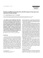
Fig. 1. The proposed device in assembly form, consisting of an internal (grey) and an external (blue) part. Insert: sketch of the internal part (For interpretation of the references
to colour in this figure legend, the reader is referred to the web version of this article).
2. Materials and methods
2.1. Computational fluid dynamics (CFD) studies
For CFD simulations, ANSYS Workbench Fluids and Structures
Academic Package (ANSYS, Pennsylvania, PA, USA; version 17.1)
was used. The cases were solved as 3D domains and for the entire
geometry to be simulated.
The examined devices consisted of three main parts, viz. the flow
distributor, the 1 D channel and the 2 D domain. To investigate (lack
of) flow confinement, a solution of dye in water corresponding to
three 1 D channel volumes was introduced to the 1 D channel at a
flow rate of 5 mL min−1 . During the 1 D injection the 2 D inlet and
outlet were kept closed.
All dimensions were chosen in accordance with our 3D printing
capabilities (see Section 2.2 below). Simulations were conducted
with both empty 1 D channels and channels filled with a porous
structure. The computations involving empty 1 D channels were
in compliance with previously fabricated and studied devices, in
which iso-electric focusing was used as a separation method in the
first dimension [4,8]. The cases simulated with a porous 1 D channel represented the presence of a monolith as stationary phase. The
permeability of 1 D and 2 D porous structures was 1.7·10−13 m2 [9].
All cases were meshed in a similar manner, with size inflation
at the distributor, body sizing at the 1 D channel and edge sizing
with divisions at the 2 D area. In the 2 D domain bias was imposed
in order to have more resolution close to the wall and to the 1 D to
2 D transition area. These modifications were made to enhance the
accuracy of the CFD results.
2.2. Designing and 3D-printing
The design process was facilitated by the commercial package
Autodesk Inventor (Autodesk, San Rafael, CA, USA). The proposed
design is depicted in Fig. 1 as an assembly. It consists of two parts:
an internal (grey) and an external (blue) one. The internal part,
also shown for clarity in the insert, is the channel in which the
1 D separation takes place. Two diametric series of through-holes
are created to allow a perpendicular flow to pass through the 1 D
channel during transfer to the second dimension. The external part
comprises a flow distributor (top), the 1 D channel casing in which
the internal part is inserted, and a series of parallel 2 D channels
(bottom).
The examined device was fabricated through 3D-printing using
a Digital Light Processing (DLP) Asiga Pico 2 HD (385 nm). Printing orientation and settings were optimized for high resolution.
After 3D-printing, post processing of the parts was necessary. This
included sonication and flushing the channels with 2-propanol and
nitrogen to remove any uncured resin. When all the undesirable
material was removed, the parts were inserted in a Pico Flash
UV chamber (type DR-301C, 36 W, 365 nm, 3DXS Germany) and
cured between 30 and 90 min (depending on the part). To make the
devices connectable, straight threads (#10-32 UNC, major diameter 4.83 mm, thread pitch 0.794 mm) were created using a hand
tap, whereas the conical part at the end of the connection area was
already incorporated into the print design. In order to connect the
tubing to the flow distributor inlet, the tubing was inserted 2 mm
in the inlet channel and glued with optical glue. The connection for
the 2 D inlet was not included in the design to stay within the surface
area of the printer’s build platform and the chosen printing orientation (the part was printed horizontally). The final connections were
watertight at the pressures needed for testing.
2.3. Chemicals and materials
Asiga PlasClear V2 resin was purchased from 3DXS (Erfurt,
Germany). 2-Propanol (Biosolve BV, Valkenswaard, The
Netherlands) was used during the post-processing of the printed
parts, as well as during the flow tests. The PME Natural Food Color
–Red (product nr: PFC1022, www.deleukstetaartenshop.nl) and
PME Natural Food Color –Blue (supplied by local source) were used
during testing. Nitrogen used during the post-processing of the
printed parts was supplied by Praxair to a laboratory gas-supply
network. Optical glue was supplied by a local source.
2.4. Flow testing
Two set of experiments had to be performed; a flowconfinement investigation during the 1 D injection and transfer
from the 1 D to the 2 D. Flow-confinement tests were performed on
the fabricated device. The device was empty and a mixture of dye
dissolved in water was injected in the 1 D channel for flow visualization. Different flow rates in the range of 0.5 to 5 mL/min were
122
T. Adamopoulou et al. / J. Chromatogr. A 1577 (2018) 120–123
Fig. 2. Concentration profile of dye solution after injecting three channel volumes into the 1 D channel. Devices with porous (left) and with empty 1 D channel (right).
studied. For the second investigation, the 1 D channel was rotated
and water was injected at 1.5 ml/min from the inlet of the flow distributor. The flow profiles were recorded with a Canon EOS 1300D
camera. The experiments were performed without a holder or additional sealing.
3. Results and discussion
All designs presented in this study consisted of three main parts,
viz. a flow distributor, a 1 D channel and a 2 D domain. In these type
of devices either a monolith is assumed to be present in both the 1 D
and 2 D domains, or only in the 2 D domain, leaving the 1 D channel
empty.
3.1. Flow confinement
Flow confinement is necessary during the 1 D step. Leakage
during this step (from the first-dimension channel to the flow distributor or to the second-dimension channels) can undermine both
the first- and the second-dimension separations. In Fig. 2 exemplary
results are depicted of 1 D injections into devices without any confinement measures and assuming a monolithic packing in the 1 D
channel (left) or an empty 1 D channel (right). The desired outcome
is to have the dye present only in the 1 D channel (in high concentrations, i.e. red in the figure). Both cases in Fig.2 are seen to result
in excessive amounts of dye in other compartments of the device.
In case of an empty 1 D channel (right) leakage is observed
mainly towards the flow distributor area. In the case with a porous
1 D channel (left), dye penetrates both to the distributor and the
2 D area. The dramatic dye distribution in the latter case can be
understood by realizing that the flow in the 1 D direction creates
a pressure gradient from left to right in the figure. This gradient
makes the liquid follow the path of the least flow resistance on its
way to the outlet, making a detour through the 2 D flow distributor before exiting along the exit of the 1 D channel. One way to
enhance flow confinement would be to keep the 1 D channel empty
(right panel) and to create constrictions, such as monolithic frits,
at the outlets of the distributor, minimizing the leakage of dye to
the 2 D flow distributor (result not shown). However, an empty 1 D
channel leaves few separation options other than IEF. A different
design is needed that allows a stationary phase to be present in the
1 D channel, while achieving flow confinement and effective flow
control.
As a solution to the above problem, we propose a concept
wherein the 1 D separation takes place in a channel with a cylindrical external geometry [patent pending, nr. EP18184801.1]. This
channel can be inserted in a cylindrical housing in the 2 D device.
Both the 1 D channel and the housing contain through-holes. During
the operation of the device for the 1 D separation the through-holes
of the chamber are not aligned with the through-holes of the 1 D
channel. During the subsequent second-dimension separation, the
through-holes of the chamber are aligned with the through-holes of
the insertable channel, allowing a perpendicular flow through the
1 D channel. A great additional advantage is that the insertable 1 D
channel can easily be replaced, allowing different stationary phases
to be used for the 1 D separation. The 1 D separation may also be performed in a different housing (off-line), for example one that allows
higher pressures for the flow to pass through the full length of the
channel.
3.2. Flow testing
Some leakage (through the first hole in the internal cylinder)
was observed at very low flow rates (0.5 mL/min) at the inlet side
of the channel probably related to the residence time of the dye
solution. Also, some leakage (between the internal and the external parts) was observed at high flow rates (5 mL/min) or upon
prolonged flushing. No leakage was observed during standard operation at 1.5 or 2 mL/min. These results were obtained without any
sealing in place. Leakages can be reduced by incorporating sealing
in the device e.g. by incorporating frits or membranes in the holes
and adding O-rings or sleaves.
Fig. 3. Pictures of the device containing dye solution (a) following injection in the 1 D channel, (b) just at the start of the 2 D injection, (c) at the end of the 2 D injection.
T. Adamopoulou et al. / J. Chromatogr. A 1577 (2018) 120–123
In Fig. 3 the three main steps of operation are presented. Initially the 1 D injection takes place, while the through-holes on the
1 D channel are not aligned with the distributor and the 2 D channels (a). Afterwards the 1 D channel is rotated to achieve the desired
alignment (b). Here, the liquid present in the dead zone inside the
holes can be observed. Dead zones can be minimized, for example
by placing a frit or a membrane. Finally, frame (c) depicts the successful emptying of the 1 D channel to the 2 D, proving the principle
and correct operation of the device.
4. Conclusions
Rigorous flow confinement in the 1 D channel is required
for optimal operation of spatial comprehensive two-dimensional
liquid chromatography (x LC×x LC) devices. To achieve this a twodimensional insertable separation tool (TWIST) is proposed. This
concept allows confinement of the flow and independent separations to be performed in the different dimensions. A prototype was
made using 3D-printing technology. Further research is required
for device and material optimization, incorporation of stationary
phases and for performing actual separations. Furthermore, use of
an external holder could offer stability during the rotation of the
1 D channel and accuracy for the required alignment. Finally, with
some modifications, the TWIST concept may provide an attractive
option to realize flow confinement in spatial three-dimension liquid chromatography.
Acknowledgements
The STAMP project is funded under Horizon 2020-Excellent
Science-European Research Council (ERC), Project 694151. The sole
responsibility of this publication lies with the authors. The European Union is not responsible for any use that may be made of the
information contained therein.
We acknowledge Dr. Suhas Nawada for his advice on 3Dprinting and Liana S. Roca, Alan Rodrigo García Cicourel and Iro
K. Ventouri for their assistance during the flow testing.
123
Appendix A. Supplementary data
Supplementary material related to this article can be found, in
the online version, at doi: />09.054.
References
[1] E. Davydova, P.J. Schoenmakers, G. Vivó-Truyols, Study on the performance of
different types of three-dimensional chromatographic systems, J. Chromatogr.
A (2013), />[2] B. Wouters, E. Davydova, S. Wouters, G. Vivo-Truyols, P.J. Schoenmakers, S.
Eeltink, Towards ultra-high peak capacities and peak-production rates using
spatial three-dimensional liquid chromatography, Lab Chip 15 (2015)
4415–4422, />[3] B.W.J. Pirok, A.F.G. Gargano, P.J. Schoenmakers, Optimizing separations in
on-line comprehensive two-dimensional liquid chromatography, J. Sep. Sci.
(2017), />[4] B. Wouters, J. de Vos, G. Desmet, H. Terryn, P.J. Schoenmakers, S. Eeltink, Design
of a microfluidic device for comprehensive spatial two-dimensional liquid
chromatography, J. Sep. Sci. 38 (2015) 1123–1129, />jssc.201401192.
[5] J.P. Grinias, R.T. Kennedy, Trends in analytical chemistry advances in and
prospects of microchip liquid chromatography, Trends Analyt. Chem. 81 (2016)
110–117, />[6] E. Davydova, S. Wouters, S. Deridder, G. Desmet, S. Eeltink, P.J. Schoenmakers,
Design and evaluation of microfluidic devices for two-dimensional spatial
separations, J. Chromatogr. A 1434 (2016) 127–135, />j.chroma.2016.01.003.
[7] S. Jespers, S. Deridder, G. Desmet, A microfluidic distributor combining minimal
volume, minimal dispersion and minimal sensitivity to clogging, J. Chromatogr.
A 1537 (2018) 75–82, />[8] J. Liu, C.F. Chen, S. Yang, C.C. Chang, D.L. Devoe, Mixed-mode electrokinetic and
chromatographic peptide separations in a microvalve-integrated polymer chip,
Lab Chip 10 (2010) 2122–2129, />[9] S. Deridder, S. Eeltink, G. Desmet, Computational study of the relationship
between the flow resistance and the microscopic structure of polymer
monoliths, J. Sep. Sci. 34 (2011) 2038–2046, />201100220.