Mechanical Properties of Carbon Nanotubes potx
Bạn đang xem bản rút gọn của tài liệu. Xem và tải ngay bản đầy đủ của tài liệu tại đây (1.13 MB, 41 trang )
Mechanical Properties
of Carbon Nanotubes
Boris I. Yakobson
1
and Phaedon Avouris
2
1
Center for Nanoscale Science and Technology and
Department of Mechanical Engineering and Materials Science,
Rice University, Houston, TX, 77251–1892, USA
2
IBM T.J. Watson Research Center
Yorktown Heights, NY 10598, USA
Abstract. This paper presents an overview of the mechanical properties of carbon
nanotubes, starting from the linear elastic parameters, nonlinear elastic instabilities
and buckling, and the inelastic relaxation, yield strength and fracture mechanisms.
A summary of experimental findings is followed by more detailed discussion of the-
oretical and computational models for the entire range of the deformation ampli-
tudes. Non-covalent forces (supra-molecular interactions) between the nanotubes
and with the substrates are also discussed, due to their significance in potential
applications.
It is noteworthy that the term resilient was first applied not to nanotubes
but to smaller fullerene cages, when Whetten et al. studied the high-energy
collisions of C
60
, C
70
,andC
84
bouncing from a solid wall of H-terminated
diamond [6]. They observed no fragmentation or any irreversible atomic rear-
rangement in the bouncing back cages, which was somewhat surprising and
indicated the ability of fullerenes to sustain great elastic distortion. The very
same property of resilience becomes more significant in the case of carbon
nanotubes, since their elongated shape, with the aspect ratio close to a thou-
sand, makes the mechanical properties especially interesting and important
due to potential structural applications.
1 Mechanical Properties
and Mesoscopic Duality of Nanotubes
The utility of nanotubes as the strongest or stiffest elements in nanoscale de-
vices or composite materials remains a powerful motivation for the research in
this area. While the jury is still out on practical realization of these applica-
tions, an additional incentive comes from the fundamental materials physics.
There is a certain duality in the nanotubes. On one hand they have molecu-
lar size and morphology. At the same time possessing sufficient translational
M. S. Dresselhaus, G. Dresselhaus, Ph. Avouris (Eds.): Carbon Nanotubes,
Topics Appl. Phys. 80, 287–327 (2001)
c
Springer-Verlag Berlin Heidelberg 2001
288 Boris I. Yakobson and Phaedon Avouris
symmetry to perform as very small (nano-) crystals, with a well defined prim-
itive cell, surface, possibility of transport, etc. Moreover, in many respects
they can be studied as well defined engineering structures and many proper-
ties can be discussed in traditional terms of moduli, stiffness or compliance,
geometric size and shape. The mesoscopic dimensions (a nanometer scale di-
ameter) combined with the regular, almost translation-invariant morphology
along their micrometer scale lengths (unlike other polymers, usually coiled),
make nanotubes a unique and attractive object of study, including the study
of mechanical properties and fracture in particular.
Indeed, fracture of materials is a complex phenomenon whose theory
generally requires a multiscale description involving microscopic, mesoscopic
and macroscopic modeling. Numerous traditional approaches are based on a
macroscopic continuum picture that provides an appropriate model except at
the region of actual failure where a detailed atomistic description (involving
real chemical bond breaking) is needed. Nanotubes, due to their relative sim-
plicity and atomically precise morphology, offer us the opportunity to address
the validity of different macroscopic and microscopic models of fracture and
mechanical response. Contrary to crystalline solids where the structure and
evolution of ever-present surfaces, grain-boundaries, and dislocations under
applied stress determine the plasticity and fracture of the material, nano-
tubes possess simpler structure while still showing rich mechanical behavior
within elastic or inelastic brittle or ductile domains. This second, theoretical-
heuristic value of nanotube research supplements their importance due to
anticipated practical applications. A morphological similarity of fullerenes
and nanotubes to their macroscopic counterparts, geodesic domes and tow-
ers, compels one to test the laws and intuition of macro-mechanics in the
scale ten orders of magnitude smaller.
In the following, Sect. 2 provides a background for the discussion of nano-
tubes: basic concepts from materials mechanics and definitions of the main
properties. We then present briefly the experimental techniques used to mea-
sure these properties and the results obtained (Sect. 3). Theoretical models,
computational techniques, and results for the elastic constants, presented in
Sect. 4, are compared wherever possible with the experimental data. In theo-
retical discussion we proceed from linear elastic moduli to the nonlinear elas-
tic behavior, buckling instabilities and shell model, to compressive/bending
strength, and finally to the yield and failure mechanisms in tensile load. After
the linear elasticity, Sect. 4.1, we outline the non-linear buckling instabilities,
Sect. 4.2. Going to even further deformations, in Sect. 4.3 we discuss irre-
versible changes in nanotubes, which are responsible for their inelastic relax-
ation and failure. Fast molecular tension tests (Sect. 4.3) are followed by the
theoretical analysis of relaxation and failure (Sect. 4.4),basedonintramolec-
ular dislocation failure concept and combined with the computer simulation
evidence. We discuss the mechanical deformation of the nanotubes caused by
their attraction to each other (supramolecular interactions) and/or to, the
Mechanical Properties of Carbon Nanotubes 289
substrates, Sect. 5.1. Closely related issues of manipulation of the tubes po-
sition and shape, and their self-organization into ropes and rings, caused by
the seemingly weak van der Waals forces, are presented in the Sects. 5.2,5.3.
Finally, a brief summary of mechanical properties is included in Sect. 6.
2 Mechanics of the Small: Common Definitions
Nanotubes are often discussed in terms of their materials applications, which
makes it tempting to define “materials properties” of a nanotube itself. How-
ever, there is an inevitable ambiguity due to lack of translational invariance
in the transverse directions of a singular nanotube, which is therefore not a
material, but rather a structural member.
A definition of elastic moduli for a solid implies a spatial uniformity of
the material, at least in an average, statistical sense. This is required for an
accurate definition of any intensive characteristic, and generally fails in the
nanometer scale. A single nanotube possesses no translational invariance in
the radial direction, since a hollow center and a sequence of coaxial layers are
well distinguished, with the interlayer spacing, c, comparable with the nano-
tube radius, R. It is essentially an engineering structure, and a definition of
any material-like characteristics for a nanotube, while heuristically appeal-
ing, must always be accompanied with the specific additional assumptions
involved (e.g. the definition of a cross-section area). Without it confusion
can easily cripple the results or comparisons. The standard starting point for
defining the elastic moduli as 1/V ∂
2
E/∂ε
2
(where E is total energy as a func-
tion of uniform strain ε) is not a reliable foothold for molecular structures. For
nanotubes, this definition only works for a strain ε in the axial direction; any
other deformation (e.g. uniform lateral compression) induces non-uniform
strain of the constituent layers, which renders the previous expression mis-
leading. Furthermore, for the hollow fullerene nanotubes, the volume V is
not well defined. For a given length of a nanotube L, the cross section area A
can be chosen in several relatively arbitrary ways, thus making both volume
V = LA and consequently the moduli ambiguous. To eliminate this problem,
the intrinsic elastic energy of nanotube is better characterized by the energy
change not per volume but per area S of the constituent graphitic layer (or
layers), C =1/S ∂
2
E/∂ε
2
. The two-dimensional spatial uniformity of the
graphite layer ensures that S = lL, and thus the value of C, is unambiguous.
Here l is the total circumferential length of the graphite layers in the cross
section of the nanotube. Unlike more common material moduli, C has dimen-
sionality of surface tension, N/m, and can be defined in terms of measurable
characteristics of nanotube,
C =(1/L)∂
2
E/∂ε
2
/
dl . (1)
The partial derivative at zero strain in all dimensions except along ε yields
an analog of the elastic stiffness C
11
in graphite, while a free-boundary (no
290 Boris I. Yakobson and Phaedon Avouris
lateral traction on the nanotube) would correspond to the Young’s modulus
Y = S
−1
11
(S
11
being the elastic compliance). In the latter case, the nanotube
Young’s modulus can be recovered and used,
Y = C
dl/A , or Y = C/h , (2)
but the non-unique choice of cross-section A or a thickness h must be kept in
mind. For the bending stiffness K correspondingly, one has (κ being a beam
curvature),
K ≡ (1/L)∂
2
E/∂κ
2
= C
y
2
dl, (3)
where the integration on the right hand side goes over the cross-section length
of all the constituent layers, and y is the distance from the neutral surface.
Note again, that this allows us to completely avoid the ambiguity of the mono-
atomic layer “thickness”, and to relate only physically measurable quantities
like the nanotube energy E, the elongation ε or a curvature κ. If one adopts a
particular convention for the graphene thickness h (or equivalently, the cross
section of nanotube), the usual Young’s modulus can be recovered, Y = C/h.
For instance, for a bulk graphite h = c =0.335 nm, C = 342 N/m and Y =
1.02 GPa, respectively. This choice works reasonably well for large diameter
multiwall tubes (macro-limit), but can cause significant errors in evaluating
the axial and especially bending stiffness for narrow and, in particular, single-
wall nanotubes.
Strength and particularly tensile strength of a solid material, similarly to
the elastic constants, must ultimately depend on the strength of its inter-
atomic forces/bonds. However, this relationship is far less direct than in the
case of linear-elastic characteristics; it is greatly affected by the particular
arrangement of atoms in a periodic but imperfect lattice. Even scarce im-
perfections in this arrangement play a critical role in the material nonlinear
response to a large force, that is, plastic yield or brittle failure. Without it,
it would be reasonable to think that a piece of material would break at Y/8–
Y/15 stress, that is about 10% strain [3]. However, all single-phase solids
have much lower σ
Y
values, around Y/10
4
, due to the presence of disloca-
tions, stacking-faults , grain boundaries, voids, point defects, etc. The stress
induces motion of the pre-existing defects, or a nucleation of the new ones
in an almost perfect solid, and makes the deformation irreversible and per-
manent. The level of strain where this begins to occur at a noticeable rate
determines the yield strain ε
Y
or yield stress σ
Y
. In the case of tension this
threshold reflects truly the strength of chemical-bonds, and is expected to be
high for C–C based material.
A possible way to strengthen some materials is by introducing extrinsic
obstacles that hinder or block the motion of dislocations [32]. There is a limit
to the magnitude of strengthening that a material may benefit from, as too
many obstacles will freeze (pin) the dislocations and make the solid brittle.
A single-phase material with immobile dislocations or no dislocations at all
Mechanical Properties of Carbon Nanotubes 291
breaks in a brittle fashion, with little work required. The reason is that it is
energetically more favorable for a small crack to grow and propagate. Energy
dissipation due to crack propagation represents materials toughness, that is
a work required to advance the crack by a unit area, G>2γ (which can be
just above the doubled surface energy γ for a brittle material, but is several
orders of magnitude greater for a ductile material like copper). Since the c-
edge dislocations in graphite are known to have very low mobility, and are the
so called sessile type [36], we must expect that nanotubes per se are brittle,
unless the temperature is extremely high. Their expected high strength does
not mean significant toughness, and as soon as the yield point is reached,
an individual nanotube will fail quickly and with little dissipation of energy.
However, in a large microstructured material, the pull-out and relative shear
between the tubes and the matrix can dissipate a lot of energy, making the
overall material (composite) toughness improved. Although detailed data is
not available yet, these differences are important to keep in mind.
Compression strength is another important mechanical parameter, but its
nature is completely different from the strength in tension. Usually it does
not involve any bond reorganization in the atomic lattice, but is due to the
buckling on the surface of a fiber or the outermost layer of nanotube. The
standard measurement [37] involves the so called “loop test” where tightening
of the loop abruptly changes its aspect ratio from 1.34 (elastic) to higher
values when kinks develop on the compressive side of the loop. In nanotube
studies, this is often called bending strength, and the tests are performed
using an atomic force microscope (AFM) tip [74], but essentially in both
cases one deals with the same intrinsic instability of a laminated structure
under compression [62].
These concepts, similarly to linear elastic characteristics, should be ap-
plied to carbon and composite nanotubes with care. At the current stage of
this research, nanotubes are either assumed to be structurally perfect or to
contain few defects, which are also defined with atomic precision (the tradi-
tional approach of the physical chemists, for whom a molecule is a well-defined
unit). A proper averaging of the “molecular” response to external forces, in
order to derive meaningful material characteristics, represents a formidable
task for theory. Our quantitative understanding of inelastic mechanical be-
havior of carbon, BN and other inorganic nanotubes is just beginning to
emerge, and will be important for the assessment of their engineering poten-
tial, as well as a tractable example of the physics of fracture.
3 Experimental Observations
There is a growing body of experimental evidence indicating that carbon
nanotubes (both MWNT and SWNT) have indeed extraordinary mechanical
properties. However, the technical difficulties involved in the manipulation of
292 Boris I. Yakobson and Phaedon Avouris
these nano-scale structures make the direct determination of their mechanical
properties a rather challenging task.
3.1 Measurements of the Young’s modulus
Nevertheless, a number of experimental measurements of the Young’s mod-
ulus of nanotubes have been reported.
The first such study [71] correlated the amplitude of the thermal vibra-
tions of the free ends of anchored nanotubes as a function of temperature
with the Young’s modulus. Regarding a MWNT as a hollow cylinder with
a given wall thickness, one can obtain a relation between the amplitude of
the tip oscillations (in the limit of small deflections), and the Young’s mod-
ulus. In fact, considering the nanotube as a cylinder with the high elastic
constant c
11
=1.06 TPa and the corresponding Young’s modulus 1.02 TPa
of graphite and using the standard beam deflection formula one can calculate
the bending of the nanotube under applied external force. In this case, the
deflection of a cantilever beam of length L with a force F exerted at its free
end is given by δ = FL
3
/(3YI), where I is the moment of inertia. The ba-
sic idea behind the technique of measuring free-standing room-temperature
vibrations in a TEM, is to consider the limit of small amplitudes in the mo-
tion of a vibrating cantilever, governed by the well known fourth-order wave
equation, y
tt
= −(YI/A)y
xxxx
,whereA is the cross sectional area, and
is the density of the rod material. For a clamped rod the boundary condi-
tions are such that the function and its first derivative are zero at the origin
and the second and third derivative are zero at the end of the rod. Thermal
nanotube vibrations are essentially elastic relaxed phonons in equilibrium
with the environment; therefore the amplitude of vibration changes stochas-
tically with time. This stochastic driven oscillator model is solved in [38]to
more accurately analyze the experimental results in terms of the Gaussian
vibrational-profile with a standard deviation given by
σ
2
=
∞
n=0
σ
2
n
=0.4243
L
3
kT
Y (D
4
o
− D
4
i
)
, (4)
with D
o
and D
i
the outer and inner radii, T the temperature and σ
n
the
standard deviation. An important assumption is that the nanotube is uni-
form along its length. Therefore, the method works best on the straight,
clean nanotubes. Then, by plotting the mean-square vibration amplitude as
a function of temperature one can get the value of the Young’s modulus.
This technique was first used in [71] to measure the Young’s modulus of
carbon nanotubes. The amplitude of those oscillations was defined by means
of careful TEM observations of a number of nanotubes. The authors ob-
tained an average value of 1.8 TPa for the Young’s modulus, though there
was significant scatter in the data (from 0.4 to 4.15 TPa for individual tubes).
Although this number is subject to large error bars, it is nevertheless indica-
tive of the exceptional axial stiffness of these materials. More recently studies
Mechanical Properties of Carbon Nanotubes 293
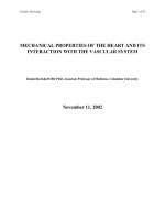
Fig. 1. Top panel: bright field TEM images of free-standing multi-wall carbon nano-
tubes showing the blurring of the tips due to thermal vibration, from 300 to 600 K.
Detailed measurement of the vibration amplitude is used to estimate the stiffness
of the nanotube beam [71]. Bottom panel: micrograph of single-wall nanotube at
room temperature, with the inserted simulated image corresponding to the best-
squares fit adjusting the tube length L,diameterd and vibration amplitude (in this
example, L =36.8nm, d =1.5nm, σ =0.33 nm, and Y =1.33 ± 0.2TPa) [38]
on SWNT’s using the same technique have been reported, Fig. 1 [38]. A larger
sample of nanotubes was used, and a somewhat smaller average value was
obtained, Y =1.25−0.35/+0.45 TPa, around the expected value for graphite
along the basal plane. The technique has also been used in [14]toestimate
the Young’s modulus for BN nanotubes. The results indicate that these com-
posite tubes are also exceptionally stiff, having a value of Y around 1.22 TPa,
very close to the value obtained for carbon nanotubes.
Another way to probe the mechanical properties of nanotubes is to use
the tip of an AFM (atomic force microscope) to bend anchored CNT’s while
simultaneously recording the force exerted by the tube as a function of the
displacement from its equilibrium position. This allows one to extract the
Young’s modulus of the nanotube, and based on such measurements [74]have
reported a mean value of 1.28±0.5 TPa with no dependence on tube diameter
for MWNT, in agreement with the previous experimental results. Also [60]
used a similar idea, which consists of depositing MWNT’s or SWNT’s bundled
in ropes on a polished aluminum ultra-filtration membrane. Many tubes are
then found to lie across the holes present in the membrane, with a fraction of
their length suspended. Attractive interactions between the nanotubes and
the membrane clamp the tubes to the substrate. The tip of an AFM is then
used to exert a load on the suspended length of the nanotube, measuring at
the same time the nanotube deflection. To minimize the uncertainty of the
applied force, they calibrated the spring constant of each AFM tip (usually
0.1 N/m) by measuring its resonant frequency. The slope of the deflection
versus force curve gives directly the Young’s modulus for a known length and
294 Boris I. Yakobson and Phaedon Avouris
tube radius. In this way, the mean value of the Young’s modulus obtained for
arc-grown carbon nanotubes was 0.81±0.41 TPa. (The same study applied to
disordered nanotubes obtained by the catalytic decomposition of acetylene
gave values between 10 to 50 GPa. This result is likely due to the higher
density of structural defects present in these nanotubes.) In the case of ropes,
the analysis allows the separation of the contribution of shear between the
constituent SWNT’s (evaluated to be close to G = 1 GPa) and the tensile
modulus, close to 1 TPa for the individual tubes. A similar procedure has also
been used [48] with an AFM to record the profile of a MWNT lying across an
electrode array. The attractive substrate-nanotube force was approximated
by a van der Waals attraction similar to the carbon–graphite interaction but
taking into account the different dielectric constant of the SiO
2
substrate;
the Poisson ratio of 0.16 is taken from ab initio calculations. With these
approximations the Young modulus of the MWNT was estimated to be in
the order of 1 TPa, in good accordance with the other experimental results.
An alternative method of measuring the elastic bending modulus of nano-
tubes as a function of diameter has been presented by Poncharal et al. [52].
The new technique was based on a resonant electrostatic deflection of a multi-
wall carbon nanotube under an external ac-field. The idea was to apply
a time-dependent voltage to the nanotube adjusting the frequency of the
source to resonantly excite the vibration of the bending modes of the nano-
tube, and to relate the frequencies of these modes directly to the Young
modulus of the sample. For small diameter tubes this modulus is about 1
TPa, in good agreement with the other reports. However, this modulus is
shown to decrease by one order of magnitude when the nanotube diameter
increases (from 8 to 40 nm). This decrease must be related to the emergence
of a different bending mode for the nanotube. In fact, this corresponds to
a wave-like distortion of the inner side of the bent nanotube. This is clearly
shown in Fig. 2. The amplitude of the wave-like distortion increases uniformly
from essentially zero for layers close to the nanotube center to about 2–3 nm
for the outer layers without any evidence of discontinuity or defects. The
non-linear behavior is discussed in more detail in the next section and has
been observed in a static rather than dynamic version by many authors in
different contexts [19,34,41,58].
Although the experimental data on elastic modulus are not very uniform,
overall the results correspond to the values of in-plane rigidity (2) C = 340 −
440 N/m, that is to the values Y =1.0 −1.3 GPa for multiwall tubules, and
to Y =4C/d =(1.36 −1.76) TPa nm/d for SWNT’s of diameter d.
3.2 Evidence of Nonlinear Mechanics and Resilience
of Nanotubes
Large amplitude deformations, beyond the Hookean behavior, reveal nonlin-
ear properties of nanotubes, unusual for other molecules or for the graphite
fibers. Both experimental evidence and theory-simulations suggest the ability
Mechanical Properties of Carbon Nanotubes 295
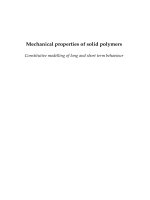
Fig. 2. A: bending modulus Y for MWNT as a function of diameter measured by
the resonant response of the nanotube to an alternating applied potential (the inset
shows the Lorentzian line-shape of the resonance). The dramatic drop in Y value
is attributed to the onset of a wave-like distortion for thicker nanotubes. D: high-
resolution TEM of a bent nanotube with a curvature radius of 400 nm exhibiting
a wave-like distortion. B,C: the magnified views of a portion of D [52]
of nanotubes to significantly change their shape, accommodating to external
forces without irreversible atomic rearrangements. They develop kinks or
ripples (multiwalled tubes) in compression and bending, flatten into deflated
ribbons under torsion, and still can reversibly restore their original shape.
This resilience is unexpected for a graphite-like material, although folding
of the mono-atomic graphitic sheets has been observed [22]. It must be at-
tributed to the small dimension of the tubules, which leaves no room for the
stress-concentrators — micro-cracks or dislocation failure piles (cf. Sect. 4.4),
making a macroscopic material prone to failure. A variety of experimental ev-
idence confirms that nanotubes can sustain significant nonlinear elastic defor-
mations. However, observations in the nonlinear domain rarely could directly
yield a measurement of the threshold stress or the force magnitudes. The
facts are mostly limited to geometrical data obtained with high-resolution
imaging.
An early observation of noticeable flattening of the walls in a close con-
tact of two MWNT has been attributed to van der Walls forces pressing the
cylinders to each other [59]. Similarly, a crystal-array [68] of parallel nano-
tubes will flatten at the lines of contact between them so as to maximize
the attractive van der Waals intertube interaction (see Sect. 5.1). Collapsed
forms of the nanotube (“nanoribbons”), also caused by van der Waals attrac-
tion, have been observed in experiment (Fig. 3d), and their stability can be
explained by the competition between the van der Waals and elastic energies
(see Sect. 5.1).
Graphically more striking evidence of resilience is provided by bent struc-
tures [19,34], Fig. 4. The bending seems fully reversible up to very large bend-
ing angles, despite the occurrence of kinks and highly strained tubule regions
296 Boris I. Yakobson and Phaedon Avouris
Fig. 3. Simulation of torsion and collapse [76]. The strain energy of a 25 nm long
(13, 0) tube as a function of torsion angle f (a). At the first bifurcation the cylinder
flattens into a straight spiral (b) and then the entire helix buckles sideways, and coils
in a forced tertiary structure (c). Collapsed tube (d) as observed in experiment [13]
in simulations, which are in excellent morphological agreement with the ex-
perimental images [34]. This apparent flexibility stems from the ability of
the sp
2
network to rehybridize when deformed out of plane, the degree of
sp
2
–sp
3
rehybridization being proportional to the local curvature [27]. The
accumulated evidence thus suggests that the strength of the carbon–carbon
bond does not guarantee resistance to radial, normal to the graphene plane
deformations. In fact, the graphitic sheets of the nanotubes, or of a plane
graphite [33] though difficult to stretch are easy to bend and to deform.
A measurement with the Atomic Force Microscope (AFM) tip detects the
“failure” of a multiwall tubule in bending [74], which essentially represents
nonlinear buckling on the compressive side of the bent tube. The measured
local stress is 15–28 GPa, very close to the calculated value [62,79]. Buckling
and rippling of the outermost layers in a dynamic resonant bending has been
directly observed and is responsible for the apparent softening of MWNT of
larger diameters. A variety of largely and reversibly distorted (estimated up
to 15% of local strain) configurations of the nanotubes has been achieved
with AFM tip [23,30]. The ability of nanotubes to “survive the crash” during
the impact with the sample/substrate reported in [17] also documents their
ability to reversibly undergo large nonlinear deformations.
Mechanical Properties of Carbon Nanotubes 297
Fig. 4. HREM images of bent nanotubes under mechanical duress. (a)and(b)sin-
gle kinks in the middle of SWNT with diameters of 0.8and1.2nm,respectively.(c)
and (d) MWNT of about 8nm diameter showing a single and a two-kink complex,
respectively [34]
3.3 Attempts of Strength Measurements
Reports on measurements of carbon nanotube strength are scarce, and remain
the subject of continuing effort. A nanotube is too small to be pulled apart
with standard tension devices, and too strong for tiny “optical tweezers”,
for example. The proper instruments are still to be built, or experimentalists
should wait until longer nanotubes are grown.
A bending strength of the MWNT has been reliably measured with the
AFM tip [74], but this kind of failure is due to buckling of graphene layers,
not the C–C bond rearrangement. Accordingly, the detected strength, up to
28.5 GPa, is two times lower than 53.4 GPa observed for non-laminated SiC
nanorods in the same series of experiments. Another group [23]estimates
the maximum sustained tensile strain on the outside surface of a bent tubule
as large as 16%, which (with any of the commonly accepted values of the
Young’s modulus) corresponds to 100–150 GPa stress. On the other hand,
some residual deformation that follows such large strain can be an evidence of
the beginning of yield and the 5/7-defects nucleation. A detailed study of the
failure via buckling and collapse of matrix-embedded carbon nanotube must
be mentioned here [41], although again these compressive failure mechanisms
are essentially different from the bond-breaking yield processes in tension (as
discussed in Sects. 4.3,4.4).
Actual tensile load can be applied to the nanotube immersed in matrix
materials, provided the adhesion is sufficiently good. Such experiments, with
298 Boris I. Yakobson and Phaedon Avouris
stress-induced fragmentation of carbon nanotube in a polymer matrix has
been reported, and an estimated strength of the tubes is 45 GPa, based on
a simple isostrain model of the carbon nanotube-matrix. It has also to be
remembered that the authors [72] interpret the contrast bands in HRTEM
images as the locations of failure, although the imaging of the carbon nano-
tube through the polymer film limits the resolution in these experiments.
While a singular single-wall nanotube is an extremely difficult object for
mechanical tests due to its small molecular dimensions, the measurement of
the “true” strength of SWNTs in a rope-bundle arrangement is further com-
plicated by the weakness of inter-tubular lateral adhesion. External load is
likely to be applied to the outermost tubules in the bundle, and its trans-
fer and distribution across the rope cross-section obscures the interpretation
of the data. Low shear moduli in the ropes (1 GPa) indeed has been re-
ported [60].
Recently, a suspended SWNT bundle-rope was exposed to a sideways pull
by the AFM tip [73]. It was reported to sustain reversibly many cycles of
elastic elongation up to 6%. If this elongation is actually transferred directly
to the individual constituent tubules, the corresponding tensile strength then
is above 45 GPa. This number is in agreement with that for multiwalled tubes
mentioned above [72], although the details of strain distribution can not be
revealed in this experiment.
Fig. 5. A: SEM image of two oppositely aligned AFM tips holding a MWCNT
which is attached at both ends on the AFM silicon tip surface by electron beam
deposition of carbonaceous material. The lower AFM tip in the image is on a soft
cantilever whose deflection is used to determine the applied force on the MWCNT.
B–D: Large magnification SEM image of the indicated region in (A) and the weld
of the MWCNT on the top AFM tip [84]
Mechanical Properties of Carbon Nanotubes 299
A direct tensile, rather than sideways, pull of a multiwall tube or a rope
has a clear advantage due to simpler load distribution, and an important step
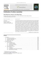
in this direction has been recently reported [84]. In this work tensile-load ex-
periments (Fig. 5) are performed for MWNTs reporting tensile strengths in
the range of 11 to 63 GPa with no apparent dependence on the outer shell
diameter. The nanotube broke in the outermost layer (“sword in sheath” fail-
ure) and the analysis of the stress-strain curves (Fig. 6) indicates a Young’s
modulus for this layer between 270 and 950 GPa. Moreover, the measured
strain at failure can be as high as 12% change in length. These high break-
ing strain values also agree with the evidence of stability of highly stressed
graphene shells in irradiated fullerene onions [5].
In spite of significant progress in experiments on the strength of nano-
tubes that have yielded important results, a direct and reliable measurement
remains an important challenge for nanotechnology and materials physics.
Fig. 6. A: Aschematic
explaining the principle
of the tensile-loading
experiment. B: Plot
of stress versus strain
curves for individual
MWCNTs [84]
4 Theoretical and Computational Models
4.1 Theoretical Results on Elastic Constants of Nanotubes
An early theoretical report based on an empirical Keating force model for a
finite, capped (5,5) tube [49] could be used to estimate a Young’s modulus
about 5 TPa (five times stiffer than iridium). This seemingly high value is
likely due to the small length and cross-section of the chosen tube (only
400 atoms and diameter d =0.7 nm). In a study of structural instabilities
300 Boris I. Yakobson and Phaedon Avouris
of SWNT at large deformations (see Sect. 4.2) the Young’s modulus that
had to be assigned to the wall was 5 TPa, in order to fit the results of
molecular dynamics simulations to the continuum elasticity theory [75,76].
From the point of view of elasticity theory, the definition of the Young’s
modulus involves the specification of the value of the thickness h of the tube
wall. In this sense, the large value of Y obtained in [75,76] is consistent
with a value of h =0.07 nm for the thickness of the graphene plane. It is
smallerthanthevalueusedinotherwork[28,42,54] that simply took the
value of the graphite interlayer spacing of h =0.34 nm. All these results
agree in the values of inherent stiffness of the graphene layer Yh = C,(2),
which is close to the value for graphite, C = Yh = 342 N/m. Further, the
effective moduli of a material uniformly distributed within the entire single
wall nanotube cross section will be Y
t
=4C/d or Y
b
=8C/d, that is different
for axial tension or bending, thus emphasizing the arbitrariness of a “uniform
material” substitution.
The moduli C for a SWNT can be extracted from the second deriva-
tive of the ab initio strain energy with respect to the axial strain, d
2
E/dε
2
.
Recent calculations [61] show an average value of 56 eV, and a very small
variation between tubes with different radii and chirality, always within the
limit of accuracy of the calculation. We therefore can conclude that the ef-
fect of curvature and chirality on the elastic properties of the graphene shell
is small. Also, the results clearly show that there are no appreciable differ-
ences between this elastic constant as obtained for nanotubes and for a single
graphene sheet. The ab initio results are also in good agreement with those
obtained in [54] using Tersoff-Brenner potentials, around 59 eV/atom, with
very little dependence on radius and/or chirality.
Tight-binding calculations of the stiffness of SWNTs also demonstrate
that the Young modulus depends little on the tube diameter and chirality [28],
in agreement with the first principles calculations mentioned above. It is pre-
dicted that carbon nanotubes have the highest modulus of all the different
types of composite tubes considered: BN, BC
3
,BC
2
N, C
3
N
4
,CN[29]. Those
results for the C and BN nanotubes are reproduced in the left panel of Fig. 7.
The Young’s modulus approaches the graphite limit for diameters of the or-
der of 1.2 nm. The computed value of C for the wider carbon nanotubes is
430 N/m; that corresponds to 1.26 TPa Young’s modulus (with h =0.34 nm),
in rather good agreement with the value of 1.28 TPa reported for multi-wall
nanotubes [74]. Although this result is for MWNT, the similarity between
SWNT is not surprising as the intra-wall C–C bonds mainly determine the
moduli. From these results one can estimate the Young’s modulus for two rel-
evant geometries: (i) multiwall tubes, with the normal area calculated using
the interlayer spacing h approximately equal to the one of graphite, and (ii)
nanorope or bundle configuration of SWNTs, where the tubes form a hexago-
nal closed packed lattice, with a lattice constant of (d+0.34 nm). The results
for these two cases are presented in the right panel of Fig. 7.TheMWNT
Mechanical Properties of Carbon Nanotubes 301
Fig. 7. Left panel: Young modulus for armchair and zig-zag C- and BN- nano-
tubes. The values are given in the proper units of TPa · nm for SWNTs (left axis),
and converted to TPa (right axis) by taking a value for the graphene thickness of
0.34 nm. The experimental values for carbon nanotubes are shown on the right-
hand-side: (a)1.28TPa[74]; (b)1.25TPa[38]; (c)1TPaforMWNT[48]. Right
panel: Young’s modulus versus tube diameter in different arrangements. Open sym-
bols correspond to the multi-wall geometry (10 layer tube), and solid symbols for
the SWNT crystalline-rope configuration. In the MWNT geometry the value of
the Young’s modulus does not depend on the specific number of layers (adapted
from [61])
geometry gives a value that is very close to the graphitic one. The rope ge-
ometry shows a decrease of the Young’s modulus with the increasing tube
diameter, simply proportional to the decreasing mass-density. The computed
values for MWNT and SWNT ropes are within the range of the reported
experimental data, (Sect. 3.1).
Values of the Poisson ratio vary in different model computations within
the range 0.15–0.28, around the value 0.19 for graphite. Since these values
always enter the energy of the tube in combination with unity (5), the de-
viations from 0.19 are not, overall, very significant. More important is the
value of another modulus, associated with the tube curvature rather than
in-plane stretching. Fig. 8 shows the elastic energy of carbon and the newer
composite BN and BC
3
SWNT. The energy is smaller for the composite than
for the carbon tubules. This fact can be related to a small value of the elastic
constants in the composite tubes as compared to graphite. From the results
of Fig. 8 we clearly see that the strain energy of C, BN and BC
3
nanotubes
follows the D
/d
2
law expected from linear elasticity theory, cf. (5). This de-
pendence is satisfied quite accurately, even for tubes as narrow as (4, 4). For
carbon armchair tubes the constant in the strain energy equation has a value
of D
=0.08 eV nm
2
/ atom (and up to 0.09 for other chiral tubes) [61]. Pre-
vious calculations using Tersoff and Tersoff-Brenner potentials [54]predict
the same dependence and give a value of D
∼ 0.06 eV nm
2
/ atom and D
∼
0.046 eV nm
2
/ atom. The latter corresponds to the value D =0.85 eV in the
energy per area as in (5), since the area per atom is 0.0262 nm
2
.Wenotein
302 Boris I. Yakobson and Phaedon Avouris
Fig. 8. Ab initio results for the total strain energy per atom as a function of the
tubule diameter, d,forC-(solid circle), BC
3
-(solid triangle)andBN-(open circle)
tubules. The data points are fitted to the classical elastic function 1/d
2
.Theinset
shows in a log plot more clearly the 1/d
2
dependence of the strain energy for all
these tubes. We note that the elasticity picture holds down to sub-nanometer scale.
The three calculations for BC
3
tubes correspond to the (3, 0), (2, 2) and (4, 0) tubes
(adapted from [7,46,47,56])
Fig. 8 that the armchair (n, n) tubes are energetically more stable as com-
pared to other chiralities with the same radius. This difference is, however,
very small and decreases as the tube diameter increases. This is expected,
since in the limit of large radii the same graphene value is attained, regardless
of chirality. It is to some extent surprising that the predictions from elasticity
theory are so similar to those of the detailed ab initio calculations. In [1]a
complementary explanation based on microscopic arguments is provided. In
a very simplified model the energetics of many different fullerene structures
depend on a single structural parameter: the planarity φ
π
, which is the angle
formed by the π-orbitals of neighbor atoms. Assuming that the change in total
energy is mainly due to the change in the nearest neighbor hopping interac-
tion between these orbitals, and that this change is proportional to cos(φ
π
),
the d
−2
behavior is obtained. By using non-self-consistent first-principles cal-
culations they have obtained a value of D
=0.085 eV nm
2
/ atom, similar to
the self-consistent value given above.
4.2 Nonlinear Elastic Deformations and Shell Model
Calculations of the elastic properties of carbon nanotubes confirm that they
are extremely rigid in the axial direction (high tensile) and more readily dis-
Mechanical Properties of Carbon Nanotubes 303
tort in the perpendicular direction (radial deformations), due to their high
aspect ratio. The detailed studies, stimulated first by experimental reports
of visible kinks in the molecules, lead us to conclude that, in spite of their
molecular size, nanotubes obey very well the laws of continuum shell the-
ory [2,39,70].
One of the outstanding features of fullerenes is their hollow structure,
built of atoms densely packed along a closed surface that defines the overall
shape. This also manifests itself in dynamic properties of molecules, which
greatly resemble the macroscopic objects of continuum elasticity known as
shells. Macroscopic shells and rods have long been of interest: the first study
dates back to Euler, who discovered the elastic instability. A rod subject
to longitudinal compression remains straight but shortens by some fraction
ε, proportional to the force, until a critical value (Euler force) is reached. It
then becomes unstable and buckles sideways at ε>ε
cr
, while the force almost
does not vary. For hollow tubules there is also a possibility of local buckling
in addition to buckling as a whole. Therefore, more than one bifurcation can
be observed, thus causing an overall nonlinear response of nanotubes to the
large deforming forces (note that local mechanics of the constituent shells
may well still remain within the elastic domain).
In application to fullerenes, the theory of shells now serves a useful guide
[16,25,63,75,76,78], but its relevance for a covalent-bonded system of only
a few atoms in diameter was far from being obvious. MD simulations seem
better suited for objects that small. Perhaps the first MD-type simulation in-
dicating the macroscopic scaling of the tubular motion emerged in the study
of nonlinear resonance [65]. Soon results of detailed MD simulations for a
nanotube under axial compression allowed one to introduce concepts of elas-
ticity of shells and to adapt them to nanotubes [75,76]. MD results for other
modes of load have also been compared with those suggested by the contin-
uum model and, even more importantly, with experimental evidence [34](see
Fig. 4 in Sect. 3.2).
Figure 9 shows a simulated nanotube exposed to axial compression.The
atomic interaction was modeled by the Tersoff-Brenner potential, which re-
produces the lattice constants, binding energies, and the elastic constants of
graphite and diamond. The end atoms were shifted along the axis by small
steps and the whole tube was relaxed by the conjugate-gradient method while
keeping the ends constrained. At small strains the total energy (Fig. 9a) grows
as E(ε)=(
1
2
)E
·ε
2
,whereE
= 59 eV/atom. The presence of four singular-
ities at higher strains was quite a striking feature, and the patterns (b)–(e)
illustrate the corresponding morphological changes. The shading indicates
strain energy per atom, equally spaced from below 0.5 eV (brightest) to
above 1.5 eV (darkest). The sequence of singularities in E(ε) corresponds to
a loss of molecular symmetry from D
∞h
to S
4
, D
2h
, C
2h
and C
1
.Thisevo-
lution of the molecular structure can be described within the framework of
continuum elasticity.
304 Boris I. Yakobson and Phaedon Avouris
Fig. 9. Simulation of a (7, 7) nanotube exposed to axial compression, L =6nm.
The strain energy (a) displays four singularities corresponding to shape changes.
At ε
c
=0.05 the cylinder buckles into the pattern (b), displaying two identical
flattenings, “fins”, perpendicular to each other. Further increase of ε enhances this
pattern gradually until at ε
2
=0.076 the tube switches to a three-fin pattern
(c), which still possesses a straight axis. In a buckling sideways at ε
3
=0.09 the
flattenings serve as hinges, and only a plane of symmetry is preserved (d). At
ε
4
=0.13 an entirely squashed asymmetric configuration forms (e)(from[75])
The intrinsic symmetry of a graphite sheet is hexagonal, and the elastic
properties of two-dimensional hexagonal structures are isotropic. A curved
sheet can also be approximated by a uniform shell with only two elastic
parameters: flexural rigidity D, and its resistance to an in-plane stretching,
the in-plane stiffness C. The energy of a shell is given by a surface integral
of the quadratic form of local deformation,
E =
1
2
{D[(κ
x
+ κ
y
)
2
− 2(1 −ν)(κ
x
κ
y
− κ
2
xy
)] (5)
+
C
(1 −ν
2
)
[(ε
x
+ ε
y
)
2
− 2(1 −ν)(ε
x
ε
y
− ε
2
xy
)]}dS ,
Mechanical Properties of Carbon Nanotubes 305
where κ is the curvature variation, ε is the in-plane strain, and x and y are
local coordinates). In order to adapt this formalism to a graphitic tubule, the
values of D and C are identified by comparison with the detailed ab initio and
semi-empirical studies of nanotube energetics at small strains [1,54]. Indeed,
the second derivative of total energy with respect to axial strain corresponds
to the in-plane rigidity C (cf. Sect. 3.1). Similarly, the strain energy as a
function of tube diameter d corresponds to 2D/d
2
in (5). Using the data
of [54], one obtains C = 59 eV/atom = 360 J/m
2
,andD =0.88 eV. The
Poisson ratio ν =0.19 was extracted from a reduction of the diameter of a
tube stretched in simulations. A similar value is obtained from experimental
elastic constants of single crystal graphite [36]. One can make a further step
towards a more tangible picture of a tube as having wall thickness h and
Young’s modulus Y
s
. Using the standard relations D = Yh
3
/12(1 − ν
2
)and
C = Y
s
h, one finds Y
s
=5.5TPaandh =0.067 nm. With these parameters,
linear stability analysis [39,70] allows one to assess the nanotube behavior
under strain.
To illustrate the efficiency of the shell model, consider briefly the case
of imposed axial compression. A trial perturbation of a cylinder has a form
of Fourier harmonics, with M azimuthal lobes and N half-waves along the
tube (Fig. 10, inset), i.e. sines and cosines of arguments 2My/d and Nπx/L.
At a critical level of the imposed strain, ε
c
(M,N), the energy variation (4.1)
vanishes for this shape disturbance. The cylinder becomes unstable and lowers
its energy by assuming an (M,N)-pattern. For tubes of d =1nmwith
the shell parameters identified above, the critical strain is shown in Fig. 10.
According to these plots, for a tube with L>10 nm the bifurcation is first
attained for M =1,N = 1. The tube preserves its circular cross section and
Fig. 10. The critical strain levels for a continuous, 1 nm wide shell-tube as a func-
tion of its scaled length L/N. A buckling pattern (M,N ) is defined by the number
of half-waves 2M and N in y and x directions, respectively, e.g., a (4, 4)-pattern is
shownintheinset. The effective moduli and thickness are fit to graphene (from [75])
306 Boris I. Yakobson and Phaedon Avouris
buckles sideways as a whole; the critical strain is close to that for a simple
rod,
ε
c
=1/2(πd/L)
2
, (6)
or four times less for a tube with hinged (unclamped) ends. For a shorter
tube the situation is different. The lowest critical strain occurs for M =
2(andN ≥ 1, see Fig. 10), with a few separated flattenings in directions
perpendicular to each other, while the axis remains straight. For such a local
buckling, in contrast to (6), the critical strain depends little on length and
estimates to ε
c
=4
D/C d
−1
=(2/
√
3)(1 − ν
2
)
−1/2
hd
−1
in the so-called
Lorenz limit. For a nanotube one finds,
ε
c
=0.077 nm/d . (7)
Specifically, for the 1 nm wide tube of length L = 6 nm, the lowest critical
strains occur for the M =2andN = 2 or 3 (Fig. 10), and are close to
the value obtained in MD simulations, (Fig.9a). This is in accord with the
two- and three-fin patterns seen in Figs. 9b,c. Higher singularities cannot be
quantified by the linear analysis, but they look like a sideways beam buckling,
which at this stage becomes a non-uniform object.
Axially compressed tubes of greater length and/or tubes simulated with
hinged ends (equivalent to a doubled length) first buckle sideways as a whole
at a strain consistent with (6). After that the compression at the ends results
in bending and a local buckling inward. This illustrates the importance of
the “beam-bending” mode, the softest for a long molecule and most likely
to attain significant amplitudes due to either thermal vibrations or environ-
mental forces. In simulations of bending, a torque rather than force is applied
at the ends and the bending angle θ increases stepwise. While a notch in
the energy plot can be mistaken for numerical noise, its derivative dE/dθ
drops significantly, which unambiguously shows an increase in tube compli-
ance — a signature of a buckling event. In bending, only one side of a tube
is compressed and thus can buckle. Assuming that it buckles when its local
strain, ε = K · (d/2), where K is the local curvature, is close to that in axial
compression, (7), we estimate the critical curvature as
K
c
=0.155 nm/d
2
. (8)
This is in excellent agreement (within 4%) with extensive simulations of single
wall tubes of various diameters, helicities and lengths [34]. Due to the end
effects, the average curvature is less than the local one and the simulated
segment buckles somewhat earlier than at θ
c
= K
c
L, which is accurate for
longer tubes.
In simulations of torsion, the increase of azimuthal angle φ between the
tube ends results in energy and morphology changes shown in Fig. 3.Inthe
continuum model, the analysis based on (5) is similar to that outlined above,
Mechanical Properties of Carbon Nanotubes 307
except that it involves skew harmonics of arguments like Nπx/L ± 2My/d.
For overall beam-buckling (M =1),
φ
c
=2(1+ν)π (9)
and for the cylinder-helix flattening (M =2),
φ
c
=0.055 nm
3/2
L/d
5/2
. (10)
The latter should occur first for L<136 d
5/2
nm, which is true for all tubes
we simulated. However, in simulations it occurs later than predicted by (10).
The ends, kept circular in simulation, which is physically justifiable, by a
presence of rigid caps on normally closed ends of a molecule, deter the through
flattening necessary for the helix to form (unlike the local flattening in the
case of an axial load).
In the above discussion, the specific values of the parameters C and D
(or Y and h) are chosen to achieve the best correspondence between the
elastic-shell and the MD simulation within the same study, performed with the
Tersoff-Brenner potential. Independent studies of nanotube dynamics under
compression generally agree very well with the above description, although
they reveal reasonable deviations in the parameter values [16,25]. More ac-
curate and realistic values can be derived from the TB or the ab initio calcu-
lations [1,7,57] of the elastic shell, and can be summarized in the somewhat
“softer but thicker” shell [76]. Based on a most recent study [28]oneobtains
effective shell parameters C = 415 J/m
2
and D =1.6eV=2.6 × 10
−19
J,
that is correspondingly Y
s
=4.6TPaandh =0.09 nm, cf. Sect. 4.1.
Simulations of nanotubes under mechanical duress lead to shapes very
different in appearance. At the same time there are robust traits in common:
a deformation, proportional to the force within Hooke’s law, eventually leads
to a collapse of the cylinder and an abrupt change in pattern, or a sequence
of such events. The presence of a snap-through buckling of nanotubes allows
for a possibility of “shape memory”, when in an unloading cycle the switch
between patterns occurs at a somewhat lower level of strain. A small hys-
teresis observed in simulations is practically eliminated by thermal motion at
any finite temperature. However, this hysteresis is greatly enhanced by the
presence of van der Waals attraction which causes the tube walls to “stick”-
flatten together after the collapse, Fig. 3d[13]. The simulations at even a
low temperature (e.g. 50 K) shows strongly enhanced thermal vibrations in
the vicinity of every pattern switch, while before and after the transition
only barely noticeable ripples are seen. Physically, this indicates softening of
the system, when one of the eigenvalues tends to zero in the vicinity of the
bifurcation.
While several reports focus on a nonlinear dynamics of an open-end
SWNT, when the terminal ring atoms are displaced gradually in simula-
tion, a more realistic interaction of a cap-closed SWNT with the (diamond
or graphite) substrates has been studied recently [25]. An inward cap collapse
308 Boris I. Yakobson and Phaedon Avouris
and/or sideways sliding of the nanotube tip along the substrate are observed,
in addition to the buckling of the tubule itself. Furthermore, an interaction
of a small (four SWNT) bundle and a double-wall tubule with the substrates
has been also reported [26].
An atomistic modeling of multi-layer tubes remains expensive. It makes
extrapolation of the continuum model tempting, but involves an interlayer
van der Waals interaction. The flexural rigidity scales as ∼ h
3
in case of a
coherent, and as ∼ h for an incoherent stack of layers sliding with respect to
each other when the tube is deformed; this affects the mechanical properties
and still has to be investigated.
Direct simulations of the tubules under hydrostatic pressure have not been
reported to the best of our knowledge. In this scale anisotropic lateral forces
in a molecular crystal packing are more plausible than a uniform pressure.
An ability of a shell-tubule to bifurcate in a flattened form makes it an exam-
ple of a two-level system, which manifests in the phase-transition behavior of
SWNT crystal, as was first described in [68] and is now indicated by several
experimental reports. While the faceting in the triangular crystal packing re-
sults in a partial wall flattening, a singular tubule under hydrostatic pressure
can collapse completely. One can resort to continuum elasticity and estimate
apressureleadingtoaninwardbucklingasp
c
=2Y (h/d)
3
, that is thou-
sands of atmospheres for a nanometer tube. However, it drops fast with the
diameter and is assisted by a flattening effects of twisting or bending and
by van der Waals attraction between the opposite walls [13]. Such collapse
cannot occur simultaneously throughout the significant SWNT length, but
rather propagates at a certain speed depending on the ambient over-pressure
u ∝
(p −p
c
). This pressure dependence [76] is similar to the observations
on macroscopic objects like underwater pipelines [50].
4.3 Atomistics of High Strain-Rate Failure
The simulations of compression, torsion, and tension described above
(Sect. 4.2) do not show any bond breaking or atoms switching their posi-
tions, in spite of the very large local strain in the nanotubes. This supports
the study of axial tension, where no shape transformations occur up to an
extreme dilation. How strong in tension is a carbon nanotube? Since the
tensile load does not lead to any shell-type instabilities, it is transferred
more directly to the chemical bond network. The inherent strength of the
carbon-carbon bond indicates that the tensile strength of carbon nanotubes
might exceed that of other known fibers. Experimental measurements remain
complex (Sect. 3.3) due to the small size of the grown single tubes. In the
meantime, some tests are being done in computer modeling, especially well
suited to the fast strain rate [75,76,77,78]. Indeed, a simulation of an ob-
ject with thousand atoms even using a classical potential interaction between
atoms is usually limited to picoseconds up to nanoseconds of real physical
Mechanical Properties of Carbon Nanotubes 309
time. This is sufficiently long by molecular standards, as is orders of magni-
tude greater than the periods of intramolecular vibrations or intermolecular
collision times. However, it is still much less than a normal test-time for a
material, or an engineering structure. Therefore a standard MD simulation
addresses a “molecular strength” of the CNT, leaving the true mechanisms
of material behavior to the more subtle considerations (Sect. 4.4).
In MD simulation, the high-strain-rate test proceeds in a very peculiar
manner. Fast stretching simply elongates the hexagons in the tube wall, un-
til at the critical point an atomic disorder suddenly nucleates: one or a few
C–C bonds break almost simultaneously, and the resulting “hole” in a tube
wall becomes a crack precursor (see Fig. 11a). The fracture propagates very
quickly along the circumference of the tube. A further stage of fracture dis-
plays an interesting feature, the formation of two or more distinct chains of
atoms, = C = C = C = , spanning the two tube fragments, Fig. 11b.
The vigorous motion (substantially above the thermal level) results in fre-
quent collisions between the chains; they coalesce, and soon only one such
chain survives. A further increase of the distance between the tube ends
does not break this chain, which elongates by increasing the number of car-
bon atoms that pop out from both sides into the necklace. This scenario is
similar to the monatomic chain unraveling suggested in field-emission exper-
Fig. 11. High strain rate tension of a two-wall tube begins from the outermost
layer, nucleating a crack precursor (a), where the atomic size is reduced to make
the internal layer visible. Eventually it leads to the formation of monatomic chains
(b)(from[77])
310 Boris I. Yakobson and Phaedon Avouris
iments [53], where the electrostatic force unravels the tube like the sleeve
of a sweater. Notably, the breaking strain in such fast-snap simulations is
about 30%, and varies with temperature and the strain rate. (For a rope
of nanotubes this translates to a more than 150 GPa breaking stress.) This
high breaking strain value is consistent with the stability limit (inflection
point on the energy curve) of 28% for symmetric low-temperature expansion
of graphene sheet [64], and with some evidence of stability of highly stresses
graphene shells in irradiated fullerene onions [5].
4.4 Yield Strength and Relaxation Mechanisms in Nanotubes
Fast strain rate (in the range of 100 MHz) simulations correspond to the
elongation of the tubule at percents of the speed of sound. In contrast to
such “molecular tension test”, materials engineering is more concerned with
the static or slow tension conditions, when the sample is loaded during sig-
nificantly longer time. Fracture, of course, is a kinetic process where time is
an important parameter. Even a small tension, as any non-hydrostatic stress,
makes a nanotube thermodynamically meta-stable and a generation of de-
fects energetically favorable. In order to study a slow strength-determining
relaxation process, preceding the fast fracture, one should either perform
extensive simulations at exceedingly elevated temperature [9,10], or apply
dislocation failure theory [79,81]. It has been shown that in a crystal lattice
such as the wall of a CNT, a yield to deformation must begin with a homo-
geneous nucleation of a slip by the shear stress present. The non-basal edge
dislocations emerging in such a slip have a well-defined core, a pentagon-
heptagon pair, 5/7. Therefore, the prime dipole is equivalent to the Stone–
Wales (SW) defect [20](Fig.12). The nucleation of this prime dislocation
dipole “unlocks” the nanotube for further relaxation: either brittle cleavage
or a plastic flow. Remarkably, the latter corresponds to a motion of disloca-
tions along the helical paths (glide “planes”) within the nanotube wall. This
causes a stepwise (quantized) necking, when the domains of different chi-
ral symmetry and, therefore, different electronic structure are formed, thus
coupling the mechanical and electrical properties [79,80]. It has further been
shown [10,51,62,79,80,81,85] that the energetics of such nucleation explicitly
depend on nanotube helicity.
Below, we deduce [79,81], starting with dislocation theory, the atomistics
of mechanical relaxation under extreme tension. Locally, the wall of a nano-
tube differs little from a single graphene sheet, a two-dimensional crystal of
carbon. When a uniaxial tension σ (N/m — for the two-dimensional wall it
is convenient to use force per unit length of its circumference) is applied it
can be represented as a sum of expansion (locally isotropic within the wall)
and a shear of a magnitude σ/2 (directed at ±45
◦
with respect to tension).
Generally, in a macroscopic crystal the shear stress relaxes by a movement of
dislocations, the edges of the atomic extra-planes. Burgers vector b quantifies
the mismatch in the lattice due to a dislocation [32]. Its glide requires only
Mechanical Properties of Carbon Nanotubes 311
Fig. 12. Stone–Wales (SW) dipole embedded
in a nanotube hexagonal wall [67]
local atomic rearrangements and presents the easiest way for strain release,
provided there is sufficient thermal agitation. In an initially perfect lattice
such as the wall of a nanotube, a yield to a great axial tension begins with a
homogeneous nucleation of a slip, when a dipole of dislocations (a tiny loop
in three-dimensional case) first has to form. The formation and further glide
are driven by the reduction of the applied-stress energy, as characterized by
the elastic Peach-Koehler force on a dislocation failure. The force component
along b is proportional to the shear in this direction and thus depends on the
angle between the Burgers vector and the circumference of the tube,
f
b
= −
1
2
σ|b|sin 2θ, (11)
The max |f
b
| is attained on two ±45
◦
lines, which mark the directions of a
slip in an isotropic material under tension.
The graphene wall of the nanotube is not isotropic; its hexagonal symme-
try governs the three glide planes — the three lines of closest zigzag atomic
packing, oriented at 120
◦
to each other (corresponding to the {101 l} set of
planes in three-dimensional graphite). At non-zero shear these directions are
prone to slip. The corresponding c-axis edge dislocations involved in such
a slip are indeed known in graphite [21,36]. The six possible Burgers vec-
tors 1/3a2
11 0 have a magnitude b = a =0.246 nm (lattice constant),
and the dislocation core is identified as a 5/7 pentagon-heptagon pair in
the honeycomb lattice of hexagons. Therefore, the primary nucleated dipole
must have a 5/7/7/5 configuration (a 5/7 attached to an inverted 7/5 core).
This configuration is obtained in the perfect lattice (or a nanotube wall) by
a90
◦
rotation of a single C–C bond, well known in fullerene science as a
Stone–Wales diatomic interchange [20]. One is led to conclude that the SW