Toyota Forklitf Mode 7FB1525 vol 2 Forklift Service Repair Manual
Bạn đang xem bản rút gọn của tài liệu. Xem và tải ngay bản đầy đủ của tài liệu tại đây (7.44 MB, 317 trang )
FOREWORD
This Manual (Volume 2) contains diagnostics service procedures of electrical controller of the TOYOTA ELECTRIC POWERED FORKLIFT 7FB10
to 30 series and 7FBJ35.
For maintenance, specifications and repair procedures for the chassis, body
and material handling system, refer to Volume 1 (Pub. No. CE315)
Please use these manuals for providing quick, correct servicing of the corresponding forklift models.
This manual deals with the above models as of September 1999. Please
understand that disagreement can take place between the descriptions in the
manual and actual vehicles due to change in design and specifications. Any
change or modifications thereafter will be informed by Toyota Industrial Equipment Parts & Service News.
SECTION INDEX
NAME
SECTION
GENERAL
BATTERY
CHARGER
CONTROLLER (CONNECTOR INSPECTION LIST)
MLUTI-DISPLAY FUNCTIONS
ELECTRICAL SYSTEM
TROUBLESHOOTING
MOTOR
DRIVE UNIT
FRONT AXLE
REAR AXLE
STEERING
BRAKE
BODY
MATERIAL HANDLING SYSTEM
MAST
CYLINDER
OIL PUMP
OIL CONTROL VALVE
SAS FUNCTIONS (OPT)
APPENDIX
0
1
2
3
4
Sections indicated by solid characters are included in this manual.
Sections indicated by half-tone characters: See vol. 1.
5
6
7
8
9
10
11
12
13
14
15
16
17
18
19
0-1
GENERAL
Page
EXTERIOR VIEWS................................................. 0-2
VEHICLE MODEL .................................................. 0-3
FRAME NUMBER .................................................. 0-4
OPERATIONAL TIPS ............................................. 0-5
JACK-UP POINT.................................................... 0-6
HOISTING THE VEHICLE ..................................... 0-7
CAUTION FOR TOWING ...................................... 0-7
CIRCUIT TESTER.................................................. 0-8
0
0-2
EXTERIOR VIEWS
0-3
VEHICLE MODEL
Classification
Series
Vehicle model
Controller type
Voltage (V)
7FB10
AC Micon controller
48
7FBH10
↑
↑
7FB14
↑
↑
7FBH14
↑
↑
7FB15
↑
↑
7FBH15
↑
↑
40-7FB15
↑
↑
7FB18
↑
↑
7FBH18
↑
↑
7FB20
↑
↑
7FBH20
↑
↑
40-7FB20
↑
↑
7FB25
↑
↑
7FBH25
↑
↑
40-7FB25
↑
↑
3.0 ton model
7FB30
↑
80
3.5 ton model
7FBJ35
↑
↑
Model
1.0 ton model
1.35 ton model
1 ton series
1.5 ton model
1.8 ton model
2.0 ton model
2 ton series
2.5 ton model
3 ton series
0
0-4
FRAME NUMBER
Drive motor model
Vehicle model
Punching format
Punching position
7FB10
7FBH10
7FB14
7FBH14
1 ton series
AP11
7FB18–10001
7FB15
Frame number
punching position
7FBH15
7FB18
7FBH18
40-7FB15
7FB20
AP15
7FBH20
7FB25–10001
7FB25
2 ton series
7FBH25
40-7FB20
AP15
407FB25–10001
40-7FB25
7FB30
3 ton series
AP16
7FBJ35–10001
7FBJ35
Note:
in place of [–] on vehicles for EEC.
0-5
OPERATIONAL TIPS
1.
Safe operation
(1) After jacking up, always support with wooden blocks or rigid stands.
(2) When hoisting the vehicle or its heavy component, use wire rope(s) with a sufficient reserve in load
capacity.
(3) Always disconnect the battery plug before the inspection or servicing of electrical parts.
2.
Tactful operation
(1) Prepare the mechanic tools, necessary measuring instruments (circuit tester, megger, oil pressure
gauge, etc.) and SSTs before starting operation.
(2) Before disconnecting wiring, always check the cable color and wiring state.
(3) When overhauling functional parts, complicated portions or related mechanisms, arrange the parts
neatly to prevent confusion.
(4) When disassembling and inspecting such a precision part as the control valve, use clean tools and
operate in a clean location.
(5) Follow the described procedures for disassembly, inspection and reassembly.
(6) Replace, gaskets, packing and O-rings with new ones each time they are disassembled.
(7) Use genuine Toyota parts for replacement.
(8) Use specified bolts and nuts. Observe the specified tightening torque at the time of reassembly.
(Tighten to the center of the specified tightening torque range.)
If no tightening torque is specified, tighten the bolt or nut according to the standard tightening torque
table.
3.
Protection of functional parts
(1) Thoroughly check each connector for any failure in or imperfect connection before reconnecting the
battery plug after the end of vehicle inspection or maintenance.
Failure in or imperfect connection of connectors related to controllers, especially, may
damage elements inside the controllers.
4.
Confirming defect status
Do not start immediate disassembly or replacement, but first confirm if such disassembly or replacement is actually needed.
5.
Handling of waste fluid, etc.
When draining waste fluid from the vehicle, always receive it with an appropriate container.
Since careless or arbitrary discharge or disposal of oil, fuel, coolant, oil filter, battery or any other
harmful substance may cause adverse affect to people or environmental destruction, sort each waste
and always ask an authorized contractor for appropriate disposal.
6.
Handling of electronic parts
(1) Never apply impacts to electronic parts such as a microcomputer or relay.
(2) Never let electronic parts be exposed to a high temperature or humidity.
(3) Do not touch connector pins since they may be deformed or be damaged due to static electricity.
0
0-6
JACK-UP POINT
Strictly observe the following instructions when jacking up the vehicle.
•
When a load is on the fork, unload it and park the vehicle on a flat floor. Be sure to avoid an inclined or
rugged place.
•
Use a jack with ample capacity and jack up the vehicle at the specified jack-up point. Jacking up at any
other point will be dangerous.
•
Never operate while the vehicle is held with a jack. Always support the frame with a wooden block
after jacking up.
•
In any case, never let a part of the body (including hands and feet) be under the jacked-up vehicle.
123
12312
12 :
Jack-up point
:
Wooden block or stand
setting point
0-7
HOISTING THE VEHICLE
Always hoist each part of the vehicle at the specified position. Never hoist at any other position because it
is very dangerous.
A
B
Slinging the head guard can be done in two
illustrated ways.
Case A:
Remove the head guard sheet.
case B:
If the fiber or wire rope comes into contact
with a rear combination lamp, remove the lamp
ASSY.
When hoisting the vehicle, sling with a fiber or
wire rope at the mast hook hole and the rear
end of the head guard.
CAUTION FOR TOWING
1.
When towing the forklift, always lift the rear wheels
away from the ground.
2.
The traveling speed in towing must not exceed the
maximum traveling speed of the forklift.
3.
Always set the key switch to OFF and the direction
switch to the neutral position before starting towing.
In case of towing by connection with a wire rope with
the operator on the forklift, however, set the key switch
to ON (PS operation) and always set the direction
switch to the neutral position.
4.
Before towing, either remove the fork or take an action to prevent fork contact with the ground due to
bounding.
0-8
CIRCUIT TESTER
Circuit testers are available in both the analog and digital types. They should be used selectively according
to the purpose of measurement.
Analog type: This type is convenient for observing movement during operation, but the measured value
should only be used for reference or rough judgement.
Digital type: Fairly accurate reading is possible, but it is difficult to observe the variation or movement.
1.
Difference in measurement results with the digital type and analog type
* The result may be different between measurements with the analog type and digital type.
Always use a circuit tester according to its operation manual.
Cautions when the polarities are different between the analog type and digital type are described
below.
(1) Analog circuit tester
Forward direction
Reverse direction
Measurement result example
Tester range: kΩ range
Analog type
Continuity exists
Forward
11 kΩ
No continuity
Reverse
∞
(2) Digital circuit tester
Forward direction
Reverse direction
Measurement result example
Tester range: MΩ range
Digital type
No continuity
Forward
1
Continuity exists
Reverse
2 MΩ
0-9
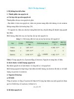
2.
Difference in result of measurement with circuit tester
The circuit tester power supply voltage depends on the tester type. 1.5 V, 3.0 V or 6.0 V is used.
The resistance of a semiconductor such as a diode varies with the circuit tester power supply voltage.
The diode characteristics are shown in the figure below.
(mA)
The resistance values of the same semiconductor measured with two types of circuit testers having different power
supply voltages are different.
6
Forward current
5
4
3
This manual describes the results of measurement with a
circuit tester whose power supply voltage is 3.0 V.
Germanium
diode
2
Silicon diode
1
0
3.
0.1 0.2
0.3 0.4 0.5 0.6
Forward voltage
0.7
0.8
(V)
Difference in measurement result by measurement range (analog type)
In the analog type circuit tester, changing the measurement range switches over the internal circuit to
vary the circuit resistance. Even when the same diode is measured, the measurement result varies
with the measurement range.
Always use the range described in the repair manual for
measurement.
Resistor
Meter
Current flow
0Ω
Variable resistor
Resistor
Range: × 10
Resistor
Range: × 1
Power source: 1.5 V
Red
(SW1)
3-1
CONTROLLER
Page
BOARD INSPECTION ............................................ 3-2
3
3-2
BOARD INSPECTION
When the cause of a trouble is judged to exist in the CPU board or the DC/MD board, connect SST
09240-23400-71 or 09230-13700-71 to the corresponding connector and measure the applied voltage
and resistance at each connector.
Always disconnect the battery plug before measuring the resistance.
Caution:
Always disconnect the battery plug before removing or installing the CPU board or the DC/MD
board.
Note:
When replacing the CPU or DC/MD board since it is judged as the cause of a trouble as the result
of troubleshooting, always measure the applied voltage and resistance of each related portion.
(1) SST setting method
Set the key switch to OFF and disconnect the battery plug.
Connect the SST to the corresponding connector pin.
Caution:
Carefully connect the SST to the correct connector pin by confirming the pin NO. since incorrect
connection may damage normal portions.
SST09240-23400-71
Connectors to which SST 09240-24300-71 is applicable
CPU board:
CN101 ~ CN104
DC/MD board: CN111 ~ CN113
SCPU board:
CN140 ~ CN142
DC/SD board: CN148
Connectors to which SST 09230-13700-71 is applicable
CPU board:
CN105 ~ CN107
DC/MD board: CN108 ~ CN110
SCPU board:
CN146, CN144 and CN145
DC/SD board: CN147
SST09230-13700-71
3-3
(2) Measurement method and standard list
How to read the list
Tester probe
Connector pin No.
→
→
→
Tester probe
Connector No. ↔ Connector No.
Conditions
Standard
Remarks
Approx. 0 V
(45, DSF)
(51, LS-)
Key switch OFF, DSF OFF
Approx. 5 V
→
Key switch OFF, DSF ON
→
CN101-26
→
CN101-1
Part name
3
Conditions for
measurement
Level No.
Traveling and load handling systems
CPU board
CN101 connector basic conditions (battery plug ON, key switch ON)
Connector No.↔ Connector No.
Conditions
Standard
CN101-1
(45, DSF)
CN101-26
(51, LS-)
Key switch OFF, DSF ON
Key switch OFF, DSF OFF
Approx. 0 V
Approx. 5 V
CN101-2
(46, DSR)
CN101-26
(51, LS-)
Key switch OFF, DSR ON
Key switch OFF, DSR OFF
Approx. 0 V
Approx. 5 V
CN101-3
(65, LSB)
CN101-26
(51, LS-)
Key switch OFF, LSB ON
Key switch OFF, LSB OFF
Approx. 5 V
Approx. 0 V
CN101-4
(66, LSPB)
CN101-26
(51, LS-)
Key switch OFF, LSPB ON
Key switch OFF, LSPB OFF
Approx. 5 V
Approx. 0 V
CN101-5
(67, LSD)
CN101-26
(51, LS-)
Key switch OFF, LSD ON (with shorting connector)
Key switch OFF, LSD OFF
Approx. 0 V
Approx. 5 V
CN101-6
Unused
–
CN101-7
Unused
–
CN101-8
Unused
–
CN101-9
(307, SMTSA)
Immeasurable
–
CN101-10
(308, SMTSK)
Immeasurable
–
Unused
–
CN101-12
(309, SSTMA)
Immeasurable
–
CN101-13
(310, SSTMK)
Immeasurable
–
CN101-11
(63, LSAT1)
CN101-14
(93, M15V)
CN101-26
(51, LS-)
Approx. 15 V
Remarks
3-4
Connector No.↔ Connector No.
CN101-15
(146, BIBC)
Conditions
Immeasurable
Standard
–
CN101-16
(61, LSTF)
CN101-26
(51, LS-)
Key switch OFF, LSTF ON
Key switch OFF, LSTF OFF
Approx. 0 V
Approx. 5 V
CN101-17
(62, LSTR)
CN101-26
(51, LS-)
Key switch OFF, LSTR ON
Key switch OFF, LSTR OFF
Approx. 0 V
Approx. 5 V
CN101-18
(70, SWTK)
CN101-26
(51, LS-)
Key switch OFF, SWTK ON
Key switch OFF, SWTK OFF
Approx. 0 V
Approx. 5 V
CN101-19
(90, MH1)
CN101-26
(51, LS-)
Lift cylinder at the bottom position
Approx. 0 V
CN101-20
(91, MH2-1)
CN101-26
(51, LS-)
Lift cylinder at the bottom position
Approx. 5 V
CN101-21
(92, MH2-2)
CN101-26
(51, LS-)
Lift cylinder at the bottom position
Approx. 5 V
CN101-22
(69, LSAT2)
Unused
–
CN101-23
Unused
–
CN101-24
(LSOPT2)
Unused
–
CN101-25
(145, BIBD)
Immeasurable
–
CN101-26
(51, LS-)
CN101-26
(51, LS-)
Approx. 0 V
CN101-27
(OPTO)
Unused
–
CN101-28
Unused
–
CN101-29
Unused
–
CN101-30
Unused
–
CN101-31
Unused
–
CN101-32
(60, LSL)
CN101-26
(51, LS-)
Key switch OFF, LSL ON
Key switch OFF, LSL OFF
Approx. 5 V
Approx. 0 V
CN101-33
Unused
–
CN101-34
Unused
–
Remarks
3-5
CN102 connector basic conditions (battery plug ON, key switch ON)
Connector No.↔ Connector No.
Conditions
Standard
CN102-1
(64, SWAC)
CN101-22
(69, LSAT2)
Key switch OFF, SWAC ON
Key switch OFF, SWAC OFF
Approx. 0 V
4V~5V
CN102-2
(52, POTA)
CN101-22
(69, LSAT2)
Key switch OFF, accelertor pedal full depression
0.5 V ~ 3 V
CN102-3
(AOPT)
Unused
CN102-4
(56, POTT)
CN101-22
(69, LSAT2)
CN102-5
(59, SPL)
CN101-22
(69, LSAT2)
Variation upon changeover from forward to
backward tilting
–
0.5 V ~ 4 V
0.5 V ~ 4 V
CN102-6
(81, SSD1)
Traveling in stopped state
Approx. 15 V
or 0 V
CN102-7
(82, SSD2)
Traveling in stopped state
Approx. 15 V
or 0 V
CN102-8
(84, SSP+)
CN101-22
(51, LS-)
CN102-9
(85, SSP-)
CN102-8
(84, SSP+)
CN102-10
(86, TD+)
CN101-22
(51, LS-)
Approx. 4.6 V
CN102-11
(87, TD-)
CN101-22
(51, LS-)
1V~4V
CN102-12
(88, TP+)
CN101-22
(51, LS-)
Approx. 5 V
C102-13
(89, TP-)
CN101-22
(51, LS-)
1V~4V
CN102-14
(53, POTA+)
CN101-22
(51, LS-)
Approx. 4.6 V
CN102-15
(54, AOPT+)
Approx. 0 V
Resistance measurement with battery OFF
Unused
Approx. 600 Ω
–
CN102-16
(57, POTT+)
CN101-22
(51, LS-)
Approx. 4.6 V
CN102-17
(58, SPL+)
CN101-22
(51, LS-)
Approx. 5 V
CN102-18
(80, SSD+)
CN101-22
(51, LS-)
Approx. 14 V
CN102-19
(83, SSD-)
CN101-22
(51, LS-)
Approx. 0 V
CN102-20
Unused
–
CN102-21
Unused
–
CN102-22
(51, POT-)
CN101-22
(51, LS-)
Remarks
Approx. 0 V
3
3-6
CN103 connector basic conditions (battery plug OFF, key switch ON)
Connector No.↔ Connector No.
Conditions
Standard
CN103-1
(3, SOLL+)
CN103-2
(4, SOLL-)
Measurement with
CN103-2
probe in contact with
CN103-2
(4, SOLL-)
CN103-1
(3, SOLL+)
Resistance measurement with battery OFF
Approx. 10 Ω
CN103-3
(41, B48V)
CN104-10
(N2, N2)
1·2 ton series
3 ton, J3.5 ton
Approx. 48 V
Approx. 80 V
CN103-4
(43, VBKY)
CN104-10
(N2, N2)
Key switch OFF
Key switch ON
1·2 ton series
3 ton, J3.5 ton
Approx. 0 V
CN103-6
(6, SOLT-)
Measurement during forward tilting with
in contact with CN103-6
CN103-6
(6, SOLT-)
CN103-5
(5, SOLT+)
Resistance measurement with battery OFF
CN103-7
(41, VBBT)
CN104-10
(N2, N2)
CN103-8
(44, VBMB)
CN104-10
(N2, N2)
CN103-10
(16, D15V)
probe
Approx. 11 V
Approx. 10 Ω
Approx. 48 V
1·2 ton series
3 ton, J3.5 ton
Key switch OFF
Approx. 48 V
Approx. 80 V
Approx. 0 V
Unused
–
CN104-10
(N2, N2)
CN103-11
CN103-12
(14, GNDD)
Approx. 11 V
Approx. 48 V
Approx. 80 V
CN103-5
(5, SOLT+)
CN103-9
Remarks
14 V ~ 15 V
Unused
–
CN104-10
(N2, N2)
Approx. 0 V
CN103-13
(144, SMTDK)
Immeasurable
–
CN103-14
(143, SDTMK)
Immeasurable
–
CN103-15
(142, SDTMA)
Immeasurable
–
CN103-16
(141, SMTDA)
Immeasurable
–
CN104 connector basic conditions (battery plug ON, key switch ON)
Connector No.↔ Connector No.
Conditions
Standard
CN104-1
(N2, N2C)
CN104-10
(N2, N2)
Approx. 0 V
CN104-2
(54, CSBATT)
CN104-10
(N2, N2)
Approx. 7 V
CN104-3
Unused
1·2 ton series
3 ton, J3.5 ton
–
CN104-4
(18, B80V)
CN104-10
(N2, N2)
Approx. 0 V
Approx. 80 V
CN104-5
(75, CSD+)
CN104-10
(N2, N2)
14 V ~ 15 V
CN104-6
(75, CSP+)
CN104-10
(N2, N2)
14 V ~ 15 V
Remarks
3-7
Connector No.↔ Connector No.
Conditions
Standard
CN104-7
(71, CSDA)
CN104-10
(N2, N2)
Approx. 7 V
CN104-8
(72, CSDB)
CN104-10
(N2, N2)
Approx. 7 V
CN104-9
(13, C20V)
CN104-10
(N2, N2)
Approx. 21 V
CN104-10
(N2, N2)
CN104-10
(N2, N2)
Approx. 0 V
CN104-11
(2, MB-)
CN104-13
(1, MB+)
CN104-12
(P2, VBP2)
CN104-10
(N2, N2)
CN104-13
(1, MB+)
CN104-11
(2, MB-)
Measurement with
CN104-11
CN104-14
(44, VBMB)
CN104-10
(N2, N2)
1·2 ton series
3 ton, J3.5 ton
Approx. 48 V
Approx. 80 V
CN104-15
(41, B48V)
CN104-10
(N2, N2)
1·2 ton series
3 ton, J3.5 ton
Approx. 48 V
Approx. 80 V
CN104-16
(16, D15V)
CN104-10
(N2, N2)
14 V ~ 15 V
CN104-17
(15, C15V)
CN104-10
(N2, N2)
14 V ~ 15 V
CN104-18
(73, CSPA)
CN104-10
(N2, N2)
Approx. 7 V
CN104-19
(74, CSPB)
CN104-10
(N2, N2)
Approx. 7 V
CN104-20
(78, THCD)
CN104-10
(N2, N2)
1V~4V
CN104-21
(77, THC+)
CN104-10
(N2, N2)
Approx. 5 V
CN104-22
(44, VBMB)
CN104-10
(N2, N2)
Approx. 50 V
CN104-23
(14, GNDD)
CN104-10
(N2, N2)
Approx. 0 V
CN104-24
(14, GNDC)
CN104-10
(N2, N2)
Approx. 0 V
CN104-25
(79, THCP)
CN104-10
(N2, N2)
1V~4V
CN104-26
Resistance measurement with battery OFF
Approx. 20 Ω
Approx. 50 V
Unused
probe in contact with
Approx. 11 V
–
CN104-27
(76, CSD-)
CN104-10
(N2, N2)
Approx. 0 V
CN104-28
(76, CSP-)
CN104-10
(N2, N2)
Approx. 0 V
Remarks
3-8
CN105 connector basic conditions (battery plug ON, key switch ON, direction lever at N, and motor
cable disconnection)
Connector No.↔ Connector No.
Conditions
Standard
Remarks
CN105-1
(38, FAN+)
CN104-10
(N2, N2)
Approx. 5 V
CN105-2
(38, FAN+)
CN104-10
(N2, N2)
Approx. 5 V
CN105-3
(36, FANCD)
CN104-10
(N2, N2)
Approx. 5 V Fan stopped
(Approx. 4.5 V) (fan ON)
CN105-4
(37, FANCP)
CN104-10
(N2, N2)
Approx. 5 V Fan stopped
(Approx. 4.5 V) (fan ON)
CN105-5
Unused
Approx. 6 V
CN105-6
(39, DDC)
CN104-10
(N2, N2)
Approx. 4 V
CN105-7
(40, PDC)
CN104-10
(N2, N2)
Approx. 4 V
CN105-8
(94, CKFAND+)
CN104-10
(N2, N2)
CN105-9
(97, CKFAND-)
CN105-10
(98, CKFANP+)
Immeasurable
CN105-11
(99, CKFANP-)
CN105-11
(99, CKFANP-)
CN105-12
CN105-13
CN105-14
(100, CHGFAN)
Approx. 0 V Fan stopped
(Approx. 0.5 V) (fan ON)
Approx. 0 V Fan stopped
(Approx. 0.5 V) (fan ON)
Immeasurable
–
Unused
–
Unused
CN104-10
(N2, N2)
–
–
Approx. 5 V
3-9
CN106 connector basic conditions (battery plug ON, key switch ON, direction lever at N, and motor
cable disconnection)
Connector No.↔ Connector No.
Conditions
Standard
CN106-1
(33, TMPU+)
CN104-10
(N2, N2)
Approx. 5 V
CN106-2
(27, TMPAU-)
CN104-10
(N2, N2)
Approx. 5 V
CN106-3
(28, TMPBU-)
CN104-10
(N2, N2)
Approx. 5 V
CN106-4
(29, TMPCU-)
CN104-10
(N2, N2)
Approx. 5 V
CN106-5
(30, TMPAD-)
CN104-10
(N2, N2)
Approx. 5 V
CN106-6
(31, TMPBD-)
CN104-10
(N2, N2)
Approx. 5 V
CN106-7
(32, TMPCD-)
CN104-10
(N2, N2)
Approx. 5 V
CN106-8
(33, TMPD+)
CN104-10
(N2, N2)
Approx. 5 V
CN106-9
(35, CKPV)
CN104-10
(N2, N2)
Approx. 10 V
CN106-10
Unused
–
CN106-11
Unused
–
Remarks
CN107 connector basic conditions (battery plug ON, key switch ON, direction lever at N, and motor cable disconnection)
Connector No.↔ Connector No.
Conditions
Standard
CN107-1
(26, TMDU+)
CN104-10
(N2, N2)
Approx. 5 V
CN107-2
(20, TMDAU-)
CN104-10
(N2, N2)
Approx. 5 V
CN107-3
(21, TMDBU-)
CN104-10
(N2, N2)
Approx. 5 V
CN107-4
(22, TMDCU-)
CN104-10
(N2, N2)
Approx. 5 V
CN107-5
(23, TMDAD-)
CN104-10
(N2, N2)
Approx. 5 V
CN107-6
(24, TMDBD-)
CN104-10
(N2, N2)
Approx. 5 V
CN107-7
(25, TMDCD-)
CN104-10
(N2, N2)
Approx. 5 V
CN107-8
(26, TMDD+)
CN104-10
(N2, N2)
Approx. 5 V
CN107-9
(34, CKDV)
CN104-10
(N2, N2)
Approx. 10 V
CN107-10
Unused
–
Remarks
3-10
DC/MD board
CN111 connector basic conditions
(battery plug ON, key switch ON, direction lever at neutral, and motor cable disconnection)
Connector No.↔ Connector No.
Conditions
Standard
CN111-1
CN111-14
(150, TMDAU1+) (P3, TMDAU-SD)
13 V ~ 15 V
CN111-2
CN111-15
(152, TMDAD1+) (N2, TMDAD-SD)
13 V ~ 15 V
CN111-3
CN111-16
(154, TMDBU1+) (P5, TMDBU-SD)
13 V ~ 15 V
CN111-4
CN111-14
(153, TMDAU-G) (P3, TMDAU-SD)
13 V ~ 15 V
CN111-5
CN111-15
(153, TMDAD-G) (N2, TMDAD-SD)
13 V ~ 15 V
CN111-6
CN111-16
(155, TMDBU-G) (P5, TMDBU-SD)
13 V ~ 15 V
CN111-7
CN111-24
(157, TMDBD-G) (N2, TMDBD-SD)
13 V ~ 15 V
CN111-8
CN111-25
(159, TMDCU-G) (P7, TMDCU-SD)
13 V ~ 15 V
CN111-9
CN111-26
(161, TMDCD-G) (N2, TMDCD-SD)
13 V ~ 15 V
CN111-10
Unused
–
CN111-11
CN111-24
(156, TMDBD1+) (N2, TMDBD-SD)
13 V ~ 15 V
CN111-12
CN111-25
(158, TMDCU1+) (P7, TMDCU-SD)
13 V ~ 15 V
CN111-13
CN111-26
(160, TMDCD1+) (N2, TMDCD-SD)
13 V ~ 15 V
CN111-14
(P3, TMDAU-SD)
Immeasurable
–
CN111-15
(N2, TMDAD-SD)
Immeasurable
–
CN111-16
(P5, TMDBU-SD)
Immeasurable
–
CN111-17
CN111-14
(150, TMDAU2+) (P3, TMDAU-SD)
13 V ~ 15 V
CN111-18
CN111-15
(152, TMDAD2+) (N2, MDAD-SD)
13 V ~ 15 V
CN111-19
CN111-16
(154, TMDBU2+) (P5, TMDBU-SD)
13 V ~ 15 V
CN111-20
CN111-24
(156, TMDBD2+) (N2, TMDBD-SD)
13 V ~ 15 V
CN111-21
CN111-25
(158, TMDCU2+) (P7, TMDCU-SD)
13 V ~ 15 V
CN111-22
CN111-26
(160, TMDCD2+) (N2, TMDCD-SD)
13 V ~ 15 V
CN111-23
Unused
–
Remarks
3-11
Connector No.↔ Connector No.
Conditions
Standard
CN111-24
(N2, TMDBD-SD)
Immeasurable
–
CN111-25
(P7, TMDCU-SD)
Immeasurable
–
CN111-26
(N2, TMDCD-SD)
Immeasurable
–
Remarks
CN112 connector basic conditions
(battery plug ON, key switch ON, direction lever at neutral, and motor cable disconnection)
Connector No.↔ Connector No.
Conditions
Standard
CN112-1
CN112-14
(162, TMPAU1+) (P12, TMPAU-SD)
13 V ~ 15 V
CN112-2
CN112-15
(164, TMPAD1+) (N2, TMPAD-SD)
13 V ~ 15 V
CN112-3
CN112-16
(166, TMPBU1+) (P14, TMPBU-SD)
13 V ~ 15 V
CN112-4
CN112-14
(163, TMPAU-G) (P12, TMPAU-SD)
13 V ~ 15 V
CN112-5
CN112-15
(165, TMPAD-G) (N2, TMPAD-SD)
13 V ~ 15 V
CN112-6
CN112-16
(167, TMPBU-G) (P14, TMPBU-SD)
13 V ~ 15 V
CN112-7
CN112-24
(169, TMPBD-G) (N2, TMPBD-SD)
13 V ~ 15 V
CN112-8
CN112-25
(171, TMPCU-G) (P16, TMPCU-SD)
13 V ~ 15 V
CN112-9
CN112-26
(173, TMPCD-G) (N2, TMPCD-SD)
13 V ~ 15 V
CN112-10
Unused
–
CN112-11
CN112-24
(168, TMPBD1+) (N2, TMPBD-SD)
13 V ~ 15 V
CN112-12
CN112-25
(170, TMPCU1+) (P16, TMPCU-SD)
13 V ~ 15 V
CN112-13
CN112-26
(172, TMPCD1+) (N2, TMPCD-SD)
13 V ~ 15 V
CN112-14
Immeasurable
–
CN112-15
(N2, TMPAD-SD)
Immeasurable
–
CN112-16
Immeasurable
–
(P12, TMPAU-SD)
(P14, TMPBU-SD)
CN112-17
CN112-14
(162, TMPAU2+) (P12, TMPAU-SD)
13 V ~ 15 V
CN112-18
CN112-15
(164, TMPAD2+) (N2, TMPAD-SD)
13 V ~ 15 V
CN112-19
CN112-16
(166, TMPBU2+) (P14, TMPBU-SD)
13 V ~ 15 V
CN112-20
CN112-24
(168, TMPBD2+) (N2, TMPBD-SD)
13 V ~ 15 V
Remarks
3-12
Connector No.↔ Connector No.
Conditions
Standard
CN112-21
CN112-25
(170, TMPCU2+) (P16, TMPCU-SD)
13 V ~ 15 V
CN112-22
CN112-26
(172, TMPCD2+) (N2, TMPCD-SD)
13 V ~ 15 V
CN112-23
Unused
–
CN112-24
(N2,TMPBD-SD)
Immeasurable
–
CN112-25
Immeasurable
–
Immeasurable
–
Remarks
(P16, TMPCU-SD)
CN112-26
(N2, TMPCD-SD)
CN113 connector basic conditions
(battery plug ON, key switch ON, direction lever at neutral, and motor cable disconnection)
Connector No.↔ Connector No.
Conditions
Standard
CN113-1
(41, B48V)
CN113-18
(N2, N2)
1·2 ton series
3 ton, J3.5 ton
Approx. 48 V
Approx. 80 V
CN113-2
(44, VBMB)
CN113-18
(N2, N2)
1·2 ton series
3 ton, J3.5 ton
Approx. 48 V
Approx. 80 V
CN113-3
CN113-4
(7, FAND+)
Unused
CN113-18
(N2, N2)
CN113-5
(8, FAND-)
C113-6
(9, FANP+)
–
Approx. 0 V Fan stopped
(Approx. 24 V) (fan ON)
Immeasurable
CN113-18
(N2, N2)
CN113-7
(10, FANP-)
Remarks
–
Approx. 0 V Fan stopped
(Approx. 24 V) (fan ON)
Immeasurable
–
CN113-8
Unused
–
CN113-9
Unused
–
CN113-10
Unused
–
CN113-11
Unused
–
CN113-12
(14, GNDD)
CN113-18
(N2, N2)
Approx. 0 V
CN113-13
(14, GNDC)
CN113-18
(N2, N2)
Approx. 0 V
CN113-14
(15, D15V)
CN113-18
(N2, N2)
14 V ~ 15 V
CN113-15
(15, C15V)
CN113-18
(N2, N2)
14 V ~ 15 V
CN113-16
(13, C20V)
CN113-18
(N2, N2)
Approx. 21 V
CN113-17
(N2, N2)
Immeasurable
–
CN113-18
(N2, N2)
Immeasurable
–
3-13
MMP board
CN114 to CN125 connectors basic conditions (battery plug ON, key switch ON)
Connector No.↔ Connector No.
Conditions
Standard
CNOOO-1
(TM
2+)
CNOOO-3
(TM
-SD)
14 V ~ 15 V
CNOOO-2
(TM
1+)
CNOOO-3
(TM
-SD)
14 V ~ 15 V
***
***
CNOOO-3
(TM
-SD)
***
CNOOO-4
(TM
-G)
***
***
***
–
CNOOO-3
(TM
-SD)
***
–
13 V ~ 15 V
Remarks
3-14
PS system
SCPU board
CN140 connector: For software writing and not connected
CN141 connector basic conditions
(battery plug ON, key switch ON)
Connector No.↔ Connector No.
Conditions
Standard
CN141-1
(SSTXA)
Immeasuable
–
CN141-2
(SXTSA)
Immeasurable
–
CN141-3
(309, SSTMA)
Immeasurable
–
CN141-4
(307, SMTSA)
Immeasurable
–
CN141-5
(324, SS+)
CN141-15
(325, SS-)
Traveling stopped
Battery plug OFF and traveling stopped
0V
0 V, 620 Ω
CN141-5
(324, SS+)
CN141-15
(325, SS-)
Battery plug OFF and traveling stopped
620 Ω
CN141-6
(312, STS1)
Immeasurable
–
CN141-7
(313, STS2)
Immeasurable
–
CN141-8
(314, STSC)
Immeasurable
–
CN141-9
(SSTXK)
Immeasurable
–
CN141-10
(SXTSK)
Immeasurable
–
CN141-11
(310, SSTMK)
Immeasurable
–
CN141-12
(308, SMTSK)
Immeasurable
–
CN141-13
(138, SL/L-)
CN141-16
(315, STS-)
Approx. 5 V
CN141-14
(137, SL/L+)
CN141-16
(315, STS-)
Approx. 5 V
CN141-15
(325, SS-)
CN146-6
(312, STS1)
CN141-16
(315, STS-)
CN146-6
(312, STS1)
0V
CN141-17
(311, STS+)
CN141-16
(315, STS-)
Approx. 15 V
CN141-18
Traveling stopped
Unused
Approx. 2.5 V
–
Remarks