Schiller defigard 5000 defibrillator service manual
Bạn đang xem bản rút gọn của tài liệu. Xem và tải ngay bản đầy đủ của tài liệu tại đây (4.37 MB, 117 trang )
DEFIGARD 5000
Service Manual
Version 01.00
SCHILLER MEDICAL S.A.S
ZAE SUD
4, rue Louis pasteur
BP 90050
F-67162 WISSEMBOURG CEDEX
Téléphone : +33 (0) 3 88 63 36 00
Télécopie : +33 (0) 3 88 94 12 82
Internet :
E.mail :
Part : 0-48-0065
DEFIGARD 5000
Revision history
of the service manual
Version 01.00 :
0-48-0065
June 2005
Page I
June 2005
DEFIGARD 5000
WARNING
This manual shall be considered to form an integral part of the device
described.
This technical manual is intended for qualified personnel and describes
the operating, maintenance and troubleshooting procedures for
DEFIGARD 5000.
Compliance with its content is a prerequisite for proper device
performance and for the safety of the patient and operator.
The manufacturer shall only be liable for the safety, reliability and
performance of the device if:
- assembly, extensions, adjustments, modifications or repairs are
performed by the manufacturer or by persons authorised by the
manufacturer.
- the electrical installation of the facility of use complies with the
requirements applicable in the country.
- the device is used in accordance with its instructions for use.
- the spare parts used are original parts from SCHILLER.
This manual describes the device at the time of printing.
The supply of this manual does not in any event constitute permission
or approval to modify or repair a device.
The manufacturer agrees to supply all the spare parts for a period of
ten years.
All rights reserved for the devices, circuits, processes and names
appearing in this manual.
The DEFIGARD 5000 device shall be used as described in the User’s
Manual. The device may not be used for any purpose that has not been
specifically described in the manual, as such use could be hazardous.
0-48-0065
Page II
June 2005
DEFIGARD 5000
SAFETY INFORMATION
·
The product is marked as follows:
CE- 0459
in accordance with the requirements of Council Directive 93/42/EEC relating to medical
equipment, based on the essential requirements of annex I of the directive.
·
It fully meets the electromagnetic compatibility requirements of standard IEC 60601-1-2/EN
60601-2 “Electromagnetic compatibility of medical electrical devices”.
·
The device has undergone interference suppression in accordance with the requirements of
standard EN 50011, class B.
·
In order to optimise patient safety, electromagnetic compatibility, accurate measurement
indication and proper device performance, users are advised to use only original spare parts
supplied by SCHILLER. Any use of accessories other than original accessories shall be at the
exclusive risk of the user. The manufacturer shall not be liable for any damage due to the use of
incompatible accessories or consumable supplies.
·
The manufacturer shall only be liable for the safety, reliability and performance of the device if:
- assembly, configuration, modifications, extensions or repairs are made by personnel from
SCHILLER MEDICAL or personnel duly authorised by SCHILLER MEDICAL.
- the device is used in accordance with its instructions for use.
·
Any use of the device other than as described in the instructions for use shall be made at the
exclusive risk of the user.
·
This manual covers the device version and the safety standards applicable at the time of
printing. All rights reserved for the circuits, processes, names, software and devices appearing
in this manual.
·
The quality assurance system in use in the facilities of SCHILLER meets international standards
EN ISO 9001 and EN 46001.
·
Unless otherwise agreed in writing by SCHILLER, no part of the manufacturer’s literature may be
duplicated or reproduced.
0-48-0065
Page III
June 2005
DEFIGARD 5000
Safety symbols used on the device
Danger! High voltage
Conventions used in the manual
G
Danger:
indicates an imminent hazard which, if not avoided, will result in
death or serious injury to the user (and/or others).
I
Caution:
Warning indicating conditions or actions that could lead to device
or software malfunctioning.
Note:
Useful information for more effective and
operation.
F
practical device
Additional information or explanation relating to the paragraphs
preceding the note.
Manufacturer:
SCHILLER
MEDICAL SA
4, rue Louis Pasteur ZAE sud
F- 67 162 Wissembourg
Tel.
Fax
: **33 / (0) 3.88.63.36.00
: **33 / (0) 3.88.94.12.82
0-48-0065
Page IV
June 2005
DEFIGARD 5000
PRECAUTIONS WHILE TESTING THE DEVICE
While testing the DEFIGARD 5000 defibrillator, the patient may only be simulated with fixed highvoltage and high-power resistors that are well insulated from the ground or earth. Poorly insulated
devices or devices with loose contacts or devices containing components such as spark arresters or
electronic flash lamps may never be used as they could irremediably destroy the device..
0-48-0065
Page V
June 2005
DEFIGARD 5000
CONTENTS
1.
Operation_________________________________________________________ 1-1
1.1.
1.2.
1.3.
1.4.
2.
Display and controls._____________________________________________________ 1-1
Explanation of symbols used ______________________________________________ 1-3
Device operation. _______________________________________________________ 1-5
Technical specifications __________________________________________________ 1-9
Testing and maintenance ____________________________________________ 2-1
2.1. Functional testing _______________________________________________________ 2-1
2.2. Cleaning and disinfecting _________________________________________________ 2-1
3.
Troubleshooting____________________________________________________ 3-1
4.
Replacement of parts _______________________________________________ 4-1
4.1.
4.2.
4.3.
4.4.
5.
Technical description of boards________________________________________ 5-1
5.1.
5.2.
5.3.
5.4.
5.5.
5.6.
5.7.
6.
Overall description of the DEFIGARD 5000.___________________________________ 5-1
DEFI BOARD (part no. WSM0050A) ________________________________________ 5-2
CPU BOARD (part no. 3.2852) ____________________________________________ 5-31
POWER BOARD (part no. 3.2653) _________________________________________ 5-36
UPPER KEYPAD BOARD (part no. WSM0062A) _____________________________ 5-37
KEYPAD + BATTERY BOARD: (part no. WSM0060A) _________________________ 5-38
PACEMAKER BOARD: (part no. WSM0059A) ________________________________ 5-39
Device modifications ________________________________________________ 6-1
6.1.
6.2.
6.3.
6.4.
6.5.
6.6.
6.7.
7.
Device disassembly procedure _____________________________________________ 4-2
Replacing the high-voltage capacitor ________________________________________ 4-4
Reassembling the device _________________________________________________ 4-5
Replacement of parts ____________________________________________________ 4-6
Définition ______________________________________________________________ 6-1
DEFI BOARD __________________________________________________________ 6-1
CPU BOARD___________________________________________________________ 6-1
POWER BOARD________________________________________________________ 6-2
UPPER KEYPAD BOARD ________________________________________________ 6-2
KEYPAD + BATTERY BOARD _____________________________________________ 6-2
PACEMAKER BOARD ___________________________________________________ 6-2
Diagrams and layout drawings ________________________________________ 7-1
7.1.
7.2.
7.3.
7.4.
7.5.
7.6.
7.7.
7.8.
7.9.
General synoptic ________________________________________________________ 7-1
DEFI BOARD (part no. WSM0050A) ________________________________________ 7-3
CPU BOARD (part no. 3.2852) _____________________________________________ 7-6
POWER BOARD (part no. 3.2653) __________________________________________ 7-9
UPPER KEYPAD BOARD (part no. WSM0062A) _____________________________ 7-11
KEYPAD + BATTERY BOARD: (part no. WSM0060A) _________________________ 7-13
PACEMAKER BOARD: (part no. WSM0059A) ________________________________ 7-15
LCD DISPLAY TFT 800X600 : (part no. 4-30-0001) ___________________________ 7-18
LIGHTING BOARD: (part no. 4-24-0003) ____________________________________ 7-19
0-48-0065
Page VI
June 2005
Operation
1. Operation
This section briefly outlines the operating of the device. For more detailed information, please refer to the
User’s Manual.
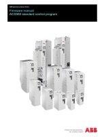
1.1. Display and controls.
2
3
4
1
5
6
14
7
8
13
12
1 : Loudspeaker
15
11
10
9
9 : ECG patient cable connection
2 : ON / OFF key
10 : NIBP connection
3 : Analysis key
11 : SOP2 connection
4 : Shock key
12 : Left paddle
5 : Microphone
13 : Printer start key
6 : Navigation, and programming key
14 : Paper compartment release
7 : Softkeys
15 : Adapter module for the different electrodes
8 : Right paddle
0-48-0065
Page 1-1
June 2005
Operation
17
16
18
20
19
21
27
22
26
25
24
23
16 : Indicator when the device is powered from an external constant power source
17 : Indicator to indicate that the batteries are charging
18 : Indicator when the device connected to the main
19 : Swing-out fastening bows
20 : Additional battery (option)
21 : Signal output (QRS-Trigger, 1-channel ECG, remote alarm)
22 : USB connector
23 : Mains connector
24 : Potential equalisation
25 : External 9…48 VDC connector
26 : RS232 interface
27 : Ethernet connector
0-48-0065
Page 1-2
June 2005
Operation
1.2. Explanation of symbols used
Symbols used on the device.
BF type signal input, protected from defibrillation
CF type signal input, protected from defibrillation
Notified body of the CE certification (G-MED)
Follow the instructions for use
Potential equalisation
Device may not be disposed of with domestic refuse.
Symbols used on the electrode package.
Open the electrode package
Peel off the protective foil
Disposable item; do not reuse
Do not bend packing
Storage temperature for the electrodes
Expiration date
0-48-0065
Page 1-3
June 2005
Operation
Symbols used on the battery
The unit/component can be recycled.
Battery may not be disposed of with domestic refuse.
Do not burn the battery
Do not saw up the battery
Do not crash the battery
The battery can be recharged
Do not short the battery
Storage temperature for the battery. Unlimited: 0 ... +40 °C
0-48-0065
Page 1-4
June 2005
Operation
1.3. Device operation.
DEFIGARD 5000 is a monitor/defibrillator designed for in-hospital use. It is started up by keeping the On/Off
key on the upper keypad pressed down for two seconds or more.
Power supply:
The device is powered by the mains, a battery (lithium ion battery only) or an external 9 - 48 VDC power
supply. It has a fixed battery in the lower slot, which can be charged from the mains or the external VDC
power supply. The capacity of the battery is sufficient for:
- 70 shocks at the maximum energy or
- 2 hours of monitor operation.
A second removable battery (optional) may be inserted in the upper slot to double the life.
Defibrillation:
DEFIGARD 5000 is a defibrillator that uses pulse biphasic waveforms - Multipulse Biowave®.
The device offers two operating modes, the semiautomatic mode, called SAD, and the manual mode. These
two operating modes depend on the type of defibrillation cartridge inserted. There are three types of cartridge
- adhesive electrode cartridge, internal electrode cartridge and handheld paddle electrode cartridge. A
window on the screen indicates the defibrillator settings.
Possibilities offered by the defibrillator:
- Manual defibrillation with adhesive electrodes
For manual defibrillation with adhesive electrodes, you need to use the cartridge for adhesive electrodes. The
charge and energy selection buttons are located on the side keypad, whilst the shock button is located on the
upper keypad.
- Semiautomatic defibrillation with adhesive electrodes
The same cartridge is used with adhesive electrodes. The device must offer the semiautomatic function.
Adhesive electrodes are available for children and adults. The device recognises the type of electrode applied
and selects the defibrillation energy levels accordingly. The control buttons for analysing and shock delivery
are located on the upper keypad.
- Internal manual defibrillation (optional)
Use the cartridge that offers the facility to use the internal defibrillation paddles. The charge and energy
selection buttons are on the side keypad. The shock button is located on the upper keypad.
- Manual defibrillation with handheld electrodes (optional)
Use the handheld electrode cartridge. The charge/shock button and the energy selection button can be found
on the electrodes.
Semiautomatic mode:
In the SAD mode, the user takes action on the basis of the messages sent by the system (in accordance with
AHA/ERC protocols).
At any time (except during CPR), if an electrode fault is detected, the AHA/ERC protocol is stopped. It is
resumed when the fault disappears.
During the analysis (which is set off by pressing the Analyse key), if a loose contact is detected, the analysis
is interrupted throughout the duration of the fault. It is automatically resumed when the fault disappears.
After an initial analysis, if the analysed ECG signal is too weak, a message asks the user to apply CPR
(cardiac pulmonary resuscitation) for one minute. The display lasts during that time, when pressing the
Analyse key starts off the analysis cycle.
After an initial analysis, if there is noise in the ECG signal, a message is displayed for one minute to ask the
user to apply CPR (cardiopulmonary resuscitation). The display lasts during that time, when pressing the
Analyse key starts off the analysis cycle.
0-48-0065
Page 1-5
June 2005
Operation
The energy is selected automatically by the system in accordance with the AHA/ERC protocol. An energy
sequence is available:
Shock 1 : Energy selected 130 J
Shock 2 : Energy selected 130 J
Shock 3 : Energy selected 150 J
.................................................................
Shock N : Energy selected 150 J
If VF is recognised during the analysis, the software automatically starts charging the capacitor with the
appropriate energy. If the charge lasts too long, it is discharged internally.
The shock is delivered manually. Pressing a key automatically delivers the energy stored in the capacitor.
The system receives the values of the delivered energy, the patient current and the patient impedance.
If the shock is not given within a given time or if the system detects a heart rhythm that does not call for a
shock, the energy is discharged internally.
ERC 2000 one-minute protocol
ANALYSIS WAITING
Ask analysis
ANALYSIS 1
VF
SHOCK 1
Wait 5 s
ANALYSIS 2
VF
SHOCK 2
No VF
Wait 1 minute
Wait 5 s
ANALYSE 3
No VF
No VF
SHOCK 3
Wait 5 s
CIRCULATION SIGN
Wait 1 s
RCP
0-48-0065
Page 1-6
June 2005
Operation
ERC 2000 three-minute protocol
ANALYSIS WAITING
Ask analysis
ANALYSIS 1
No VF
VF
No
CIRCULATION SIGN
SHOCK 1
Wait 1 s
Wait 5 s
Yes
ANALYSIS 2
START
VF
RCP
Wait 3 minutes
ASYSTOLIE ?
SHOCK 2
Wait 1 minute
Wait 5 s
ANALYSiS 3
VF
No VF
SHOCK 3
No VF
Wait 5 s
ANALYSiS 4
No VF
VF
CIRCULATION SIGN
Wait 1 s
RCP
Manual mode:
The manual mode is accessible directly when the device is turned on or when the Physician key is pressed
while in the semiautomatic mode. It unlocks the use of the defibrillator, allowing the operator to control the
device entirely.
In the manual mode, the user can defibrillate patients synchronously with an ECG.
Pacemaker (optional)
For the pacemaker function, you need to use the cartridge for adhesive electrodes. The keys for starting up
the pacemaker and setting the pacing frequency or current and the fixed, demand or overdrive mode are
located on the side keypad. If the pacemaker is operating, the defibrillation function is disabled.
ECG function
This module is always powered and the ECG signal can be collected with 3, 4 or 10-lead cable. Depending
on the configuration, the device can display up to 12 leads at the same time. Four amplitude values may be
set (0.25, 0.5, 1 and 2 cm/mV), as may two signal scanning speeds (25 and 50 mm/s).
The QRS frequency is also displayed.
0-48-0065
Page 1-7
June 2005
Operation
SPO2 function (optional)
The window of this function is only displayed on the screen when the SPO2 connector is detected by the
device. The window displays the SPO2 curve and the saturation rate.
When the screen displays the 12 leads of the ECG, the SPO2 curves disappears, but the saturation rate
remains displayed.
NIBP function (optional)
The NIBP may be set to Adult or Infant. For each configuration, you can take manual, continuous or cyclical
measurements.
The Sys, Dia and MAP values are displayed on the screen.
Memory function
The ECG curve and the trends are saved in a compact flash memory in the device.
Data transmission function
- A connection for GSM or standard modems is provided for transmitting the 12-lead ECG
- A USB connector is provided for retrieving data from the device
- An Ethernet link for upgrading software
All the connectors are located at the rear of the device.
Recorder function (optional)
The recorder can print ECG, SPO2 or trend curves.
0-48-0065
Page 1-8
June 2005
Operation
1.4. Technical specifications
·
Manufacturer
: SCHILLER MEDICAL
·
Device type
: DEFIGARD 5000
·
Dimensions
: 289 x 271 x 177 mm (height x width x depth)
·
Weight
: 5,3 kg
·
Protection case
: IPX 1
·
Power supply
Voltage
Power consumption
Battery operation
Fuses
External power supply
·
Batteriy
Battery type
Autonomy
·
Environmental conditions
Transport / storage
Operating
: 100 - 240 VAC, 50/60Hz
: 120 VA
: Up to 2 hours, option with additional battery up to 4 hours.
: 2 x 200 mAT at 250 VAC, 2 x 315 mAT at 115 VAC
: 9 - 48 VDC max. 2,5 A
: The unit is suitable for use in networks according to IEC 60601-1-2
: Lithium / ion 10,8 V 4,3 A.
: 70 schocks with maximum energy or 4 hours of monitoring (alternately 30
min on, 30 min off).
: Temperature -10 to + 50 °C
: Relative humidity 0 to 95 %, no condensation
: Atmospheric pressure 700 à 1060 hPa
: Temperature 0 à + 40 °C
: Relative humidity 30 à 95 %, no condensation
: Atmospheric pressure 500 à 1060 hPa
·
Display
Type
Dimensions
: High resolution colour LCD (800 X 600) with backlight
: 214 mm x 158,4 mm (10,4")
·
Printer
Resolution
Paper
Print speed
Recording tracks
: 8 dots / mm (amplitude-axis), 40 dots / mm (time-axis) at 25 mm / s
: Thermoreactive, Z-foldet, 72 mm width, length approx. 20 m.
: 25, 50 mm / s
: 3-channel display, with optimal width of 72 mm.
·
Connections
: ECG patient cable, SPO2, PNI.
·
Interfaces
: RS-232
: Analogue for QRS trigger, 1-chanel ECG and remote alarm
: USB
: Ethernet
·
Défibrillation pulse form
- Biphasic pulsed defibrillation impulse with fixed physiological optimum phase durations.
- Near stabilisation of the emitted energy in function with the patient resistance us ing pulse-pause
modulation depending on the measured patient resistance.
0-48-0065
Page 1-9
June 2005
Operation
·
Standard energy settings :
Adult
: 130 -130 -150 J (configurable)
Paediatric
: 15 -30 -50 J (configurable)
(automatic switch when the paediatric electrodes are connected) :
Paddle
: 0 - 2 - 4 - 8 - 15 - 30 - 50 - 90 - 130 - 180 J.
Adhesive electrodes
: 2 - 4 - 8 - 15 - 30 - 50 - 70 - 90 - 110 - 130 - 150 - 180 J.
Internal
: 2 - 4 - 6 - 8 - 15 - 30 J.
Tolerance at 50 Ω
: Tolerance à 50 Ω : ± 3 J or ± 15 % (the higher value is assumed).
·
Charging time for shock (with new batteries and after 15 discharges at max. energy output).
From shock recommendation to shock standby
: 8 s pour 180 J
Max. energy from analysis efter 15 shocks
: 25 s
Max. energy after switching on
: 29 s
·
Operating modes.
- Synchronised with heart action 25 ms after R wave.
- Unsychronised
- AED
·
Cycle time shock - shock : < 25 s
·
Charge control and monitoring :
- Automatic shock recommendation of analysis in AED mode.
- Using the set wheel on the paddle
- Using the device's keyboard
·
Patient resistance 30 to 220 Ω .
·
Display of shock standby : Key
·
Shock delivery
·
Safety discharge when :
- the heart rate does not call for defibrillation.
- after 20 seconds of the device indicating its readiness for a shock, no shock is delivered
- there is an electrode fault
- the battery voltage is insufficient.
- the device is defective
- the device is turned off.
0-48-0065
is lit.
Page 1-10
June 2005
Operation
·
Shock delivery.
- Via applied disposable adhesive defibrillation electrodes.
- Via paddles.
- Via spoons
·
Defibrillation electrode connection.
External defibrillation
: Type BF.
Internal defibrillation
: Type CF.
·
Defibrillation electrodes:
- Adult electrode
- Paediatric electrode
- Electrode cable length
·
VF/VT detection :
- Shock recommendation : in case of VF and VT (VT > 180 p/min)
- Sensitivity : 98.43 %
Specificity: 99.8 %. These values have been found with the AHA database, which contains cases
of VF and VT with and without artefacts..
- Conditions required for ECG analysis :
Minimum amplitude for the signals used > 0.15 mV , signals of < 0.15 mV are considered to show
asystole
- Definition :
Sensitivity: Correct detection of heart rates for which defibrillation shocks are recommended.
Specificity: Correct detection of heart rates for which defibrillation shocks are not recommended.
·
ECG :
Leads
Patient cable
Heart rate
Lead display
Band pass
·
NIBP - non-invasive blood pressure :
Measurement
: Automatic or manual
Measuring method
: Oscillometric
Connection
: Type CF
Measurement range :
Adults
: Sys 30...255 mmHg, dia 15...220 mmHg
Neonates
: Sys 30...135 mmHg, dia 15...110 mmHg
Accuracy
: ± 3 mmHg et ± 2 B/min
·
SPO2 (pulsoximetry) :
Amplifier
Using the Monitor
Accuracy
Calibration range
Connection
Measurement range
Displayed range
·
Saving
ECG
Events
0-48-0065
: 78 cm2 de surface active
: 28 cm2 de surface active
:2m
: Simultaneous, synchronous recording 12 leads
: 3-,4-, 10-lead cable, type CF
: 30 – 300 beats/min
: Selection of 1 to 12 simultaneous leads
: 0.5...35 Hz or 0.05...150 Hz (depending on the ECG source)
: Masimo
: Normal and sensitive
: - SPO2
Adults 1…100% ± 2
Neonates 70…100% ± 3
- PP
25 …240/min ± 4
: 70…100%
: Type CF
: SPO2 1…100%
: PP 25 …240/min
: 1…100%
: 1 hour
: 500
Page 1-11
June 2005
Testing and maintenance
2. Testing and maintenance
This section describes the test and maintenance procedures recommended with DEFIGARD 5000.
2.1. Functional testing
The device runs an automatic test every time is switched on. The test lasts less than 5 seconds and consists
in checking all the hardware functions. If a blocking error is found, an error message is displayed on the
screen and a sound alarm is emitted till the device is switched off by the operator (by pressing the Off key).
The device is blocked and goes off automatically after five minutes.
The device can run a periodic automatic test at a configurable frequency. That automatic test may be daily,
weekly or user-defined by indicating the number of days between two tests (1 to 30 days). A key for
immediately starting up the test is available as well. During the self test, all the hardware functions and the
battery charge status are tested. No information is displayed on the screen during the test. The test result is
saved and can be retrieved subsequently. The last 30 tests are saved.
If the tests do not show any error, the system goes off automatically.
If, on the other hand, a serious error is found, a sound alarm is emitted for 10 seconds every 2 minutes till the
device is switched on again. At that time, the error is displayed on the screen. The device is blocked.
A selection is available to restart all the tests.
If the tests do not show any error, the system starts up nominal operation.
If, on the other hand, a blocking error is found, the error is displayed on the screen and a sound alarm is
emitted till the device is switched off by the operator (by pressing Off). The device is blocked.
2.2. Cleaning and disinfecting
I
Caution:
Switch the device off before cleaning it. Remove the cell
before you start cleaning the device in order to eliminate the
risk of the device starting up accidentally. Also disconnect
the defibrillation electrodes of the device before cleaning.
No liquid shall be allowed to enter into the device. However,
if that does happen, the device may not be used before it is
verified by the after-sales service department.
The device or electrodes may never be cleaned with substances such as ether, acetone, esters,
aromatic chemicals etc.
Never use phenol-based cleaners or cleaners containing peroxide derivatives to disinfect the
surfaces of the housing of the device.
·
Dispose of all single-use electrodes immediately after use in order to eliminate the risk of
accidental reuse (disposal with hospital waste).
·
Before cleaning the electrode cables of sensors, disconnect them from the device. For cleaning
and disinfecting, wipe the cables with a gauze cloth moistened with cleaner or disinfectant.
Never immerse the connectors in liquid. The cleaning solution used may be any cleaning or
disinfecting solution that is commonly used in hospitals.
·
Proceed likewise with the device housing, with a cloth moistened with cleaner or disinfectant. No
liquid may be allowed to penetrate into the device during the operation.
0-48-0065
Page 2-1
June 2005
Troubleshooting
3. Troubleshooting
This section addresses the troubleshooting procedures for DEFIGARD 5000. If you have trouble locating or
correcting the problem, contact the after-sales service department of SCHILLER.
F
Note:
If an error message is displayed before you call in a Schiller
technician, note the error number and restart the device to check
that the reason for the problem is not merely a program crash.
Precautions during troubleshooting
While testing the DEFIGARD 5000 defibrillator, the patient may only be simulated with fixed highvoltage and high-power resistors that are well insulated from the ground or earth. Poorly insulated
devices or devices with loose contacts or devices containing components such as spark arresters or
electronic flash lamps may never be used as they could irremediably destroy the device.
G
Danger:
ERROR
Before any work on an open device, you need to IMPERATIVELY
CHECK IF THE HV CAPACITOR IS PROPERLY DISCHARGED.
FINDING
POSSIBLE CAUSES
CORRECTIVE ACTION
ERROR MESSAGES
Board error
(in the ECG window)
Board error
(in the SPO2 window)
Board error
(in the NIBP window)
Analogue board
Power board error
VF error
NIBP error
1. CPU board problem
1. Replace the CPU board
1. SPO2 board problem
1. Replace the SPO2 board
1. NIBP board problem
1. Replace the NIBP board
1. CPU board fault
1. POWER board fault
1. CPU board fault
1. NIBP module fault
1. Replace the CPU board
1. Replace the POWER board
1. Replace the CPU board
1. Replace the NIBP board
DEFIBRILLATOR ERROR MESSAGES
Board error
(in DEFI window)
PROCESSOR ERROR
PROGRAM ERROR
ERROR DETECTION CIRCUIT ERROR
SELECTED ENERGY
VOLTAGE REFERENCE ERROR
ADC CONVERTER ERROR
CHARGE TRANSISTOR ERROR
DISCHARGE TRANSISTOR ERROR
COMPENSATION EPROM ERROR
SHOCK BUTTON ERROR
0-48-0065
1. DEFI board problem
1. Replace the DEFI board
1. DEFI board fault
1. Program problem with
DEFI board
1. DEFI board fault
1. DEFI board fault
1. Replace the DEFI board
1. Reload the program
1. DEFI board fault
1. DEFI board fault
1. DEFI board fault
1. DEFI board fault
1. Problem with handheld
paddle cartridge
2. UPPER KEYPAD board
fault
1. Replace the DEFI board
1. Replace the DEFI board
1. Replace the DEFI board
1. Replace the DEFI board
1. Replace the cartridge
Page 3-1
1. Replace the DEFI board
1. Replace the DEFI board
2. Replace the UPPER
KEYPAD board
June 2005
Replacement of parts
4. Replacement of parts
This section addresses the issue of how to dismantle DEFIGARD 5000 in order to replace faulty parts. The
warnings below apply to all work inside the device.
G
Warning:
The DEFIGARD 5000 is a defibrillator with a high-voltage
capacitor that can be charged to a fatal voltage. The device
may only be dismantled by specially authorised and trained
personnel.
Before any work on an open device, you need to
IMPERATIVELY CHECK IF THE HV CAPACITOR IS PROPERLY
DISCHARGED.
I
I
I
0-48-0065
Caution:
Before dismantling the device, remove the battery or the cell
from its slot.
Caution:
The device contains circuits sensitive to electrostatic
discharge. All work on the DEFIGARD 5000 device shall be
performed in accordance with ESD rules. The repairs shall be
performed on an antistatic mat connected to the earth and the
operator shall wear an antistatic strap also connected to the
mat. In the event of any work on the high-voltage part of the
defibrillator, remove the antistatic strap.
Caution:
A general device test shall be performed each time the device
is opened.
Page 4-1
June 2005
Replacement of parts
4.1. Device disassembly procedure
Unfasten the 8 screws at the locations shown by the arrows.
Open the housing halfway on the right side and disconnect the four cables shown by the arrows.
0-48-0065
Page 4-2
June 2005
Replacement of parts
Now remove the two parts.
View of the front
Rep. 5
Rep. 4
View of the rear
0-48-0065
Page 4-3
June 2005
Replacement of parts
4.2. Replacing the high-voltage capacitor
G
Warning:
This operation relates to the high-voltage capacitor, which
can carry fatal charges. Before starting to work, take care to
discharge the high-voltage capacitor completely. The
terminals of the high-voltage capacitor must never be
touched directly. The high-voltage capacitor may never be
replaced by people other than specially authorised and
trained personnel.
The replacement of the HV capacitor is an extremely rare operation, as the life of an HV capacitor is
very long. However, if that is ever necessary, the HV capacitor may be replaced in accordance with
the instructions below:
IMPORTANT! IMPERATIVELY CHECK IF THE HV CAPACITOR IS PROPERLY DISCHARGED.
- Take off the cable ties and disconnect the wires.
- Lift off the capacitor, using a tool (e.g. screwdriver) for leverage, as it has been glued in
place with strong glue.
+
-
F
After removing the (fully discharged) high-voltage capacitor from the lower
part, short the three terminals of the capacitor with conducting wire.
While replacing the HV capacitor, glue it onto the support with a piece of double-sided adhesive tape.
Twist the wires and connect them, minding the polarity. Also, make sure that the wire path is as
instructed.
Check that nothing has been forgotten before you start up the device.
I
Caution:
This operation relates to an essential component of the highvoltage part. It may only be performed by specially authorised
personnel who have been trained in repairing FREDâ easy
devices.
The delivered energy must undergo testing.
0-48-0065
Page 4-4
June 2005
Replacement of parts
4.3. Reassembling the device
Reverse the procedure to reassemble the device.
Place the boards one layer after the other, starting from the bottom.
Do not forget to connect the various cables..
I
Important :
Follow the connection direction of the DEFI input HV cables,
refs. 4 and 5 (see photograph "View of front").
Check if all the boards in their grooves.
Check that the cables will not get caught when the device is
closed.
- Put the device into this position and
connect the four cables.
Front
- Set the device straight and place the
boards in the three grooves (right-hand
side).
- The battery tank wiring must be placed
between the board and tank.
- The external VDC connector must be place
between the tank and the bottom of the
0-48-0065
Page 4-5
June 2005