IEEE standard HDL base on verilog HDL
Bạn đang xem bản rút gọn của tài liệu. Xem và tải ngay bản đầy đủ của tài liệu tại đây (6.32 MB, 675 trang )
Recognized as an
American National Standard (ANSI)
The Institute of Electrical and Electronics Engineers, Inc.
345 East 47th Street, New York, NY 10017-2394, USA
Copyright © 1996 by the Institute of Electrical and Electronics Engineers, Inc.
All rights reserved. Published 1996. Printed in the United States of America
ISBN 1-55937-727-5
No part of this publication may be reproduced in any form, in an electronic retrieval system or otherwise, without the prior
written permission of the publisher.
IEEE Std 1364-1995
IEEE Standard Hardware Description
Language Based on the Verilog
¨
Hardware Description Language
Sponsor
Design Automation Standards Committee
of the
IEEE Computer Society
Approved 12 December 1995
IEEE Standards Board
Approved 1 August 1996
American National Standards Institute
Abstract:
The Verilog
¨
Hardware Description Language (HDL) is defined. Verilog HDL is a formal
notation intended for use in all phases of the creation of electronic systems. Because it is both ma-
chine readable and human readable, it supports the development, verification, synthesis, and test-
ing of hardware designs; the communication of hardware design data; and the maintenance,
modification, and procurement of hardware. The primary audiences for this standard are the imple-
mentors of tools supporting the language and advanced users of the language.
Keywords:
computer, computer languages, electronic systems, digital systems, hardware, hard-
ware design, hardware description languages, HDL, programming language interface, PLI, Verilog
HDL, Verilog PLI, Verilog
¨
IEEE Standards
documents are developed within the Technical Committees of the IEEE Societies
and the Standards Coordinating Committees of the IEEE Standards Board. Members of the com-
mittees serve voluntarily and without compensation. They are not necessarily members of the Insti-
tute. The standards developed within IEEE represent a consensus of the broad expertise on the
subject within the Institute as well as those activities outside of IEEE that have expressed an inter-
est in participating in the development of the standard.
Use of an IEEE Standard is wholly voluntary. The existence of an IEEE Standard does not imply
that there are no other ways to produce, test, measure, purchase, market, or provide other goods and
services related to the scope of the IEEE Standard. Furthermore, the viewpoint expressed at the
time a standard is approved and issued is subject to change brought about through developments in
the state of the art and comments received from users of the standard. Every IEEE Standard is sub-
jected to review at least every Þve years for revision or reafÞrmation. When a document is more
than Þve years old and has not been reafÞrmed, it is reasonable to conclude that its contents,
although still of some value, do not wholly reßect the present state of the art. Users are cautioned to
check to determine that they have the latest edition of any IEEE Standard.
Comments for revision of IEEE Standards are welcome from any interested party, regardless of
membership afÞliation with IEEE. Suggestions for changes in documents should be in the form of a
proposed change of text, together with appropriate supporting comments.
Interpretations: Occasionally questions may arise regarding the meaning of portions of standards as
they relate to speciÞc applications. When the need for interpretations is brought to the attention of
IEEE, the Institute will initiate action to prepare appropriate responses. Since IEEE Standards rep-
resent a consensus of all concerned interests, it is important to ensure that any interpretation has
also received the concurrence of a balance of interests. For this reason IEEE and the members of its
technical committees are not able to provide an instant response to interpretation requests except in
those cases where the matter has previously received formal consideration.
Comments on standards and requests for interpretations should be addressed to:
Secretary, IEEE Standards Board
445 Hoes Lane
P.O. Box 1331
Piscataway, NJ 08855-1331
USA
Authorization to photocopy portions of any individual standard for internal or personal use is
granted by the Institute of Electrical and Electronics Engineers, Inc., provided that the appropriate
fee is paid to Copyright Clearance Center. To arrange for payment of licensing fee, please contact
Copyright Clearance Center, Customer Service, 222 Rosewood Drive, Danvers, MA 01923 USA;
(508) 750-8400. Permission to photocopy portions of any individual standard for educational class-
room use can also be obtained through the Copyright Clearance Center.
Note: Attention is called to the possibility that implementation of this standard may
require use of subject matter covered by patent rights. By publication of this standard,
no position is taken with respect to the existence or validity of any patent rights in
connection therewith. The IEEE shall not be responsible for identifying all patents for
which a license may be required by an IEEE standard or for conducting inquiries into
the legal validity or scope of those patents that are brought to its attention.
iii
Introduction
(This introduction is not a part of IEEE Std 1364-1995, IEEE Standard Hardware Description Language Based on the
Verilog
¨
Hardware Description Language.)
The Verilog
¨
Hardware Description Language (Verilog HDL) was designed to be simple, intuitive, and
effective at multiple levels of abstraction in a standard textual format for a variety of design tools, including
veriÞcation simulation, timing analysis, test analysis, and synthesis. The Verilog HDL was designed by Phil
Moorby during the winter of 1983Ð1984, and it was introduced into the EDA market in 1985 as the corner-
stone of a veriÞcation simulator product.
The Verilog HDL contains a rich set of built-in primitives, including logic gates, user-deÞnable primitives,
switches, and wired logic. It also has device pin-to-pin delays and timing checks. The mixing of abstract lev-
els is essentially provided by the semantics of two data types: nets and registers. Continuous assignments, in
which expressions of both registers and nets can continuously drive values onto nets, provide the basic struc-
tural construct. Procedural assignments, in which the results of calculations involving register and net values
can be stored into registers, provide the basic behavioral construct. A design consists of a set of modules,
each of which has an I/O interface and a description of its function, which can be structural, behavioral, or a
mix. These modules are formed into a hierarchy and are interconnected with nets.
The Verilog language is extensible via the Programming Language Interface (PLI). The PLI is a collection of
routines that allows foreign functions to access information contained in a Verilog HDL description of the
design and facilitates dynamic interaction with simulation. Applications of PLI include connecting to a Ver-
ilog HDL simulator with other simulation and CAD systems, customized debugging tasks, delay calculators,
and annotators.
The language that inßuenced Verilog HDL the most was HILO-2, which was developed at Brunel University
in England under a contract to produce a test generation system for the British Ministry of Defense. HILO-2
successfully combined the gate and register transfer levels of abstraction and supported veriÞcation simula-
tion, timing analysis, fault simulation, and test generation.
In 1990, Cadence Design Systems placed the Verilog HDL into the public domain and the independent Open
Verilog International (OVI) was formed to manage and promote Verilog HDL.
In 1992, the Board of Directors of OVI began an effort to establish Verilog HDL as an IEEE standard. With
many designers all over the world designing electronic circuits with Verilog HDL, this idea was enthusiasti-
cally received by the Verilog user community. When the Project Authorization Request (1364) was approved
by the IEEE in 1993, a working group was formed and the Þrst meeting was held on October 14, 1993.
Objective
The starting point for the IEEE P1364 Working Group were the OVI LRM version 2.0 and OVI PLI versions
1.0 and 2.0. The standardization process started with the clear objective of making it easier for the user to
understand and use Verilog. The IEEE P1364 standard had to be clear, unambiguous, implementable, and not
overly constraining. Since Verilog HDL has been in use for some time, it was quite robust enough to be pre-
sented to the user community without a great deal of enhancements. The working group, therefore, decided
not to spend a lot of time extending the language, but, for the purpose of this standardization, to concentrate
on clarifying the language.
Since Verilog HDL has been in widespread use and a number of ASIC vendors have built extensive libraries
in Verilog HDL, it was very important to maintain the integrity of these existing models. With this in mind, it
iv
was decided that the intent of the working group would be to maintain the integrity of the standard and every
care would be taken not to invalidate existing models.
The standardization process
In order to clarify the language, many changes were proposed from a number of sources. The working group
met 15 times over a period of 18 months and voted on nearly 400 motions. Four drafts of the document were
generated and reviewed. It is a tribute to the hard work and dedication put forward by all the members of the
working group that this standard was completed in the short span of 18 months.
Many new sections were created, one of which is the section on scheduling semantics. A number of sections
were merged to form new sections. The two annexes containing compiler directives and system tasks were
moved into main text as two sections. Every effort has been made to clarify all ambiguities, add explana-
tions, and delete references that were deemed unnecessary.
Changes also included removing product speciÞc references and restrictions. The minimum product require-
ments for implementing this standard were clariÞed. A number of examples, Þgures, and tables were
retained in order to provide better context and explanation.
The PLI Task Force provided a clear and accurate description of OVI PLI 1.0 implementations already in
existence, and revisited the OVI PLI 2.0 speciÞcation to ensure its accuracy and completeness. The baseline
for the access routines and the task/function routines was the OVI PLI 1.0 speciÞcation. As there are a large
number of OVI PLI 1.0 routines in widespread use that were not included in the OVI PLI 1.0 document, it
was decided to consider additions to this document from the pool of existing OVI PLI 1.0 implementations.
The access routines and the task/function routines provide full backwards compatibility with Verilog HDL
software tools and PLI applications.
The baseline for the VPI routines was the existing OVI PLI 2.0 document. To this, the task force brought
new experience from the implementations in progress, which helped prove the worthiness of the previously
untested speciÞcation.
Acknowledgments
This standard is based on work originally developed by Cadence Design Systems, Inc. (in their Verilog LRM
1.6 and 2.0 and PLI documents) and Open Verilog International (in their Verilog LRM 2.0 and PLI 1.0 and
2.0). The IEEE is grateful to Cadence Design Systems and Open Verilog International for permission to use
their materials as the basis for this standard.
The IEEE Std 1364-1995 working group organization
Many individuals from many different organizations participated directly or indirectly in the standardization
process. The main body of the IEEE P1364 working group is located in the United States, with a subgroup in
Japan. Over a period of 18 months many task forces were created, of which the PLI task force was
prominent.
The members of the IEEE P1364 working group had voting privileges, and all motions had to be approved
by this group to be implemented. All task forces and subgroups focused on some speciÞc areas, and their
recommendations were eventually voted on by the IEEE P1364 working group.
v
At the time this document was approved, the IEEE P1364 working group had the following membership:
Maqsoodul (Maq) Mannan,
Chair
Yoshiharu Furui,
Vice Chair (Japan)
Alec G. Stanculescu,
Vice Chair (USA)
Lynn A. Horobin,
Secretary
Yatin Trivedi,
Technical Editor
Victor Berman John Mancini John Sanguinetti
Leigh Brady Michael McNamara Joseph P. Skudlarek
Clifford E. Cummings Elliot Mednick Stuart Sutherland
Peter Eichenberger Phil Moorby John R. Williamson
Andrew T. Lynch Gabe Moretti Alex N. ZamÞrescu
The PLI task force consisted of the following members:
Andrew T. Lynch,
PLI Task Force Leader
Stuart Sutherland,
Technical Editor
Charles A. Dawson Joel Paston Marco Zelado
Rajeev Madhavan Sathyam K. Pattanam Guoqing Zhang
David Roberts
The IEEE P1364 Japan subgroup consisted of the following members:
Yoshiharu Furui,
Vice-Chair, IEEE-1364 Working Group
Takaaki Akashi Junichi Murayama Toshiyuki Sakamoto
Kasumi Hamaguchi Masaharu Nakamura Hitomi Sato
Masato Ikeda Shouhei Oda Katsushida Seo
Masaru Kakimoto Fujio Otsuka Mitsuhiro Yasuda
Kazuya Morii Kazuhiro Yoshinaga
The following persons were members of the balloting group:
Guy Adam
H. Gordon Adshead
Unmesh Agarwala
Anant Agrawal
John Ainscough
Takaaki Akashi
Tom Albers
Glen Anderson
Lawrence F. Arnstein
Michael Atkin
Venkata Atluri
Rick Bahr
Jim Ball
Jose Baradiaran
Daniel S. Barclay
David L. Barton
Jean-Michel Berge
Victor Berman
J. Bhasker
Ron Bianchini
William D. Billowitch
Ronald D. Blanton
Miriam Blatt
James Brandt
Dennis B. Brophy
Randal E. Bryant
John A. Busco
Ben Buzonas
L. Richard Carley
Thomas Chao
Daniel Chapiro
Clive R. Charlwood
Chin-Fu Chen
Mojy C. Chian
Kai Moon Chow
Michael D. Ciletti
Joseph C. Circello
Luc Claesen
George M. Cleveland
Edmond S. Cooley
Tedd Corman
David Crohn
Clifford E. Cummings
Godfrey Paul D'Souza
Brian A. Dalio
Carlos Dangelo
Hal Daseking
Timothy R. Davis
Charles A. Dawson
Willem De Lange
Rajiv Deshmukh
Caroline DeVore-Kenney
Allen Dewey
Bill Doss
Douglas D. Dunlop
Peter Eichenberger
Hazem El Tahawy
John A. Eldon
Bassam N. Elkhoury
Ted Elkind
Brian Erickson
Robert A. Flatt
Bob Floyd
Alain Blaise Fonkoua
Douglas W. Forehand
Paul Franzon
Bill Fuchs
vi
Yoshiharu Furui
Vassilios Gerousis
Emil Girczyc
Rita A. Glover
Timothy G. Goldsbury
Alan Goodrum
Suresh Gopalakrishnan
Harutaka Goto
Kenji Goto
Brian GrifÞn
Steve Grout
Kazuyuki Hagiwara
Michael J. Haney
James P. Hanna
Anne C. Harris
Akira Hasegawa
Stuart Hecht
Shankar Hemmady
John Hillawi
Chris N. Hinds
Kazuyuki Hirakawa
Fumiyasu Hirose
Lynn A. Horobin
Tamio Hoshino
May Huang
Sylvie Hurat
Masaharu Imai
Ann Irza
Mitsuaki Ishikawa
Yoshi Ishizaka
David Jakopac
Paul Jeffs
Roger Jennings
Eugene E. Jones
Richard Jones
Tetsuro Kage
Masaru Kakimoto
Osamu Karatsu
Jake Karrfalt
Kaoru Kawamura
Masamichi Kawarabayashi
Pratibha Kelapure
Khozema Khambati
Bruce Kim
Choon B. Kim
Tsutomu Kimoto
Chris Kingsley
Masayuki Koyama
Tokinori Kozawa
Sarangan K. Kumar
Ramachandra P. Kunda
Douglas Laird
Jean Lebrun
Bill Ledbetter
Hung-Yi Lee
Shawn Leonard
Oz Levia
George Lippincott
Herbert Lopez-Aguado
Jin-Qin Lu
Andrew T. Lynch
Viranjit S. Madan
Rajeev Madhavan
Naotaka Maeda
Serge Maginot
James Magro
Wojciech P. Maly
Maqsoodul Mannan
Guillermo Maturana
Michael McNamara
Paul J. Menchini
Jean Mermet
Gerald T. Michael
Glen S. Miranker
Shankha Mitra
Kristan Monsen
John T. Montague
Patrick Moore
Gabe Moretti
David S. Morris
Chandra Moturu
Wolfgang Mueller
Shankar Ranjan Mukherjee
Yoshiaki Nagashima
David Nagle
Hiroshi Nakamura
Hiroshi Nakamura
Seiji Nakamura
Zainalabedin Navabi
Sivaram K. Nayudu
Robert N. Newshutz
Jun Numata
John W. OÕLeary
Tetsuya Okabe
Vincent Olive
Yoichi Onishi
Samir Palnitkar
Mark Papamarcos
David M. Parry
Rajesh Patil
Robert A. Pease
Mitchell Perilstein
Bruce Petrick
John Petry
Robert Piloty
Juan Pineda
Ron Poon
Jan Pukite
Selliah Rathnam
David Rich
John P. Ries
Hemant G. Rotithor
Jacques Rouillard
Paul Rowbottom
Jon Rubinstein
Stefan Rusu
Rob A. Rutenbar
Karem A. Sakallah
Toshiyuki Sakamoto
John Sanguinetti
Hitomi Sato
Larry F. Saunders
Quentin Schmierer
Michael L. Seavey
Alex Seibulescu
Shailesh Shah
Moe Shahdad
Ravi Shankar
Charles Shelor
John P. Shen
Hiroshi Shiraishi
Toru Shonai
Alexander A. Silbey
Supreet Singh
Joseph P. Skudlarek
David M. Smith
David R. Smith
William Bong H. Soon
Larry P. Soule
John Spittal
Chakra R. Srivatsa
Joseph J. Stanco
Alec G. Stanculescu
Jay K. Strosnider
Stuart Sutherland
Kinya Tabuchi
Atsushi Takahara
Donald Thomas
Partha Tirumalai
Jose A. Torres
Paul Traynar
Richard Trihy
Yatin Trivedi
Shunjen Tsay
Radha Vaidyanathan
Arie van Rhijn
Kerry Veenstra
Venkat V. Venkataraman
Sanjay Vishin
Robert A. Walker
Tsu-Hua Wang
John J. Watters
Ronald Waxman
J. Richard Weger
Paul Weil
John R. Williamson
John C. Willis
Claudia H. Ye
William R. Young
Tetsuo Yutani
Alex N. ZamÞrescu
Guoqing Zhang
vii
When the IEEE Standards Board approved this standard on 12 December 1995, it had the following mem-
bership:
E. G. ÒAlÓ Kiener,
Chair
Donald C. Loughry,
Vice Chair
Andrew G. Salem,
Secretary
*Member Emeritus
Also included are the following nonvoting IEEE Standards Board liaisons:
Satish K. Aggarwal
Steve Sharkey
Robert E. Hebner
Chester C. Taylor
Mary Lynne Nielsen
IEEE Standards Project Editor
Verilog is a registered trademark of Cadence Design Systems, Inc.
Gilles A. Baril
Clyde R. Camp
Joseph A. Cannatelli
Stephen L. Diamond
Harold E. Epstein
Donald C. Fleckenstein
Jay Forster*
Donald N. Heirman
Richard J. Holleman
Jim Isaak
Ben C. Johnson
Sonny Kasturi
Lorraine C. Kevra
Ivor N. Knight
Joseph L. KoepÞnger*
D. N. ÒJimÓ Logothetis
L. Bruce McClung
Marco W. Migliaro
Mary Lou Padgett
John W. Pope
Arthur K. Reilly
Gary S. Robinson
Ingo RŸsch
Chee Kiow Tan
Leonard L. Tripp
Howard L. Wolfman
viii
Contents
Section 1 Overview 1
Section 2 Lexical conventions 5
Section 3 Data types 13
Section 4 Expressions 27
Section 5 Scheduling semantics 45
Section 6 Assignments 50
Section 7 Gate and switch level modeling 55
Section 8 User-defined primitives (UDPs) 87
Section 8 Behavioral modeling 98
Section 10 Tasks and functions 125
Section 11 Disabling of named blocks and tasks 132
Section 12 Hierarchical structures 135
Section 13 Specify blocks 152
Section 14 System tasks and functions 172
Section 15 Value change dump (VCD) file 207
Section 16 Compiler directives 219
Section 17 PLI TF and ACC interface mechanism 228
Section 18 Using ACC routines 234
Section 19 ACC routine definitions 270
Section 20 Using TF routines 444
Section 21 TF routine definitions 449
Section 22 Using VPI routines 525
Section 23 VPI routine definitions 554
Annex A Formal syntax definition 594
Annex B List of keywords 604
ix
Annex C The acc_user.h file 605
Annex D The veriuser.h file 615
Annex E The vpi_user.h file 622
Annex F System tasks and functions 635
Annex G Compiler directives 642
Annex H Bibliography 644
Section 1 1
IEEE Standard Hardware Description
Language Based on the Verilog
¨
Hardware Description Language
Section 1
Overview
1.1 Objectives of this standard
The intent of this standard is to serve as a complete speciÞcation of the Verilog
¨
Hardware Description Language
(HDL). This document contains
Ñ The formal syntax and semantics of all Verilog HDL constructs
Ñ Simulation system tasks and functions, such as text output display commands
Ñ Compiler directives, such as text substitution macros and simulation time scaling
Ñ The Programming Language Interface (PLI) binding mechanism
Ñ The formal syntax and semantics of access routines, task/function routines, and Verilog procedural interface
routines
Ñ Informative usage examples
Ñ Listings of header Þles for PLI
1.2 Conventions used in this standard
This standard is organized into sections, each of which focuses on some speciÞc area of the language. There are sub-
clauses within each section to discuss individual constructs and concepts. The discussion begins with an introduction
and an optional rationale for the construct or the concept, followed by syntax and semantic descriptions, followed by
some examples and notes.
The verb ÒshallÓ is used through out this standard to indicate mandatory requirements, whereas the verb ÒcanÓ is used
to indicate optional features. These verbs denote different meanings to different readers of this standard:
IEEE
Std 1364-1995 IEEE STANDARD HARDWARE DESCRIPTION LANGUAGE BASED ON
2 Section 1
a) To the developers of tools that process the Verilog HDL, the verb ÒshallÓ denotes a requirement that the
standard imposes. The resulting implementation is required to enforce the requirements and to issue an error
if the requirement is not met by the input.
b) To the Verilog HDL model developer, the verb ÒshallÓ denotes that the characteristics of the Verilog HDL are
natural consequences of the language deÞnition. The model developer is required to adhere to the constraint
implied by the characteristic. The verb ÒcanÓ denotes optional features that the model developer can exercise
at discretion. If used, however, the model developer is required to follow the requirements set forth by the
language deÞnition.
c) To the Verilog HDL model user, the verb ÒshallÓ denotes that the characteristics of the models are natural
consequences of the language deÞnition. The model user can depend on the characteristics of the model
implied by its Verilog HDL source text.
1.3 Syntactic description
The formal syntax of the Verilog HDL is described using Backus-Naur Form (BNF). The following conventions are
used:
a) Lowercase words, some containing embedded underscores, are used to denote syntactic categories. For
example:
module_declaration
b) Boldface words are used to denote reserved keywords, operators, and punctuation marks as a required part of
the syntax. These words appear in a larger font for distinction. For example:
module
=>
;
c) A vertical bar separates alternative items unless it appears in boldface, in which case it stands for itself. For
example:
unary_operator ::=
+
|
-
|
!
|
~
|
&
|
~&
|
|
|
~|
|
^
|
~^
|
^~
d) Square brackets enclose optional items. For example:
input_declaration ::=
input
[range] list_of_variables
;
e) Braces enclose a repeated item unless it appears in boldface, in which case it stands for itself. The item may
appear zero or more times; the repetitions occur from left to right as with an equivalent left-recursive rule.
Thus, the following two rules are equivalent:
list_of_param_assignments ::= param_assignment
{
,
param_assignment }
list_of_param_assignments ::=
param_assignment
| list_of_param_assignment
,
param_assignment
f) If the name of any category starts with an italicized part, it is equivalent to the category name without the
italicized part. The italicized part is intended to convey some semantic information. For example,
msb_
constant_expression and
lsb_
constant_expression are equivalent to constant_expression.
The main text uses
italicized
font when a term is being deÞned, and
constant-width
font for examples, Þle
names, and while referring to constants, especially
0
,
1
,
x
, and
z
values.
IEEE
THE VERILOG
¨
HARDWARE DESCRIPTION LANGUAGE Std 1364-1995
Section 1 3
1.4 Contents of this standard
A synopsis of the sections and annexes is presented as a quick reference. There are 23 sections and 7 annexes. All the
sections and annexes A through E are normative parts of this standard. Annexes F and G are included for informative
purposes only.
1)
Overview
This section discusses the conventions used in this standard and its contents.
2)
Lexical conventions
This section describes how to specify and interpret the lexical tokens.
3)
Data types
This section describes net and reg data types. This section also discusses the parameter data type for con-
stant values and describes drive and charge strength of the values on nets.
4)
Expressions
This section describes the operators and operands that can be used in expressions.
5)
Scheduling semantics
This section describes the scheduling semantics of the Verilog HDL.
6)
Assignments
This section compares the two main types of assignment statements in the Verilog HDLÑcontinuous
assignments and procedural assignments. It describes the continuous assignment statement that drives
values onto nets.
7)
Gate and switch level modeling
This section describes the gate and switch level primitives and logic strength modeling.
8)
User-defined primitives (UDPs)
This section describes how a primitive can be deÞned in the Verilog HDL and how these primitives are
included in Verilog HDL models.
9)
Behavioral modeling
This section describes procedural assignments, procedural continuous assignments, and behavioral lan-
guage statements.
10)
Tasks and functions
This section describes tasks and functionsÑprocedures that can be called from more than one place in a
behavioral model. It describes how tasks can be used like subroutines and how functions can be used to
deÞne new operators.
11)
Disabling of named blocks and tasks
This section describes how to disable the execution of a task and a block of statements that has a speci-
Þed name.
12)
Hierarchical structures
This section describes how hierarchies are created in the Verilog HDL and how parameter values
declared in a module can be overridden.
13)
Specify blocks
This section describes how to specify timing relationships between input and output ports of a module.
14)
System tasks and functions
This section describes the system tasks and functions.
15)
Value change dump (VCD) Þle
This section describes the system tasks associated with Value Change Dump (VCD) Þle, and the format
of the Þle.
16)
Compiler directives
This section describes the compiler directives.
17)
PLI TF and ACC interface mechanism
This section describes the interface mechanism that provides a means for users to link PLI task/function
(TF) routine and access (ACC) routine applications to Verilog software tools.
18)
Using ACC routines
This section describes the ACC routines in general, including how and why to use them.
IEEE
Std 1364-1995
4 Section 1
19)
ACC routine definitions
This section describes the speciÞc ACC routines, explaining their function, syntax, and usage.
20)
Using TF routines
This section provides an overview of the types of operations that are done with the TF routines.
21)
TF routine definitions
This section describes the speciÞc TF routines, explaining their function, syntax, and usage.
22)
Using VPI routines
This section provides an overview of the types of operations that are done with the Verilog Programming
Interface (VPI) routines.
23)
VPI routine definitions
This section describes the VPI routines.
A
Formal syntax definition
This normative annex describes, using BNF, the syntax of the Verilog HDL.
B)
List of keywords
This normative annex lists the Verilog HDL keywords.
C)
The acc_user.h file
This normative annex provides a listing of the contents of the
acc_user.h
Þle.
D)
The veriuser.h file
This normative annex provides a listing of the contents of the
veriuser.h
Þle.
E)
The vpi_user.h file
This normative annex provides a listing of the contents of the
vpi_user.h
Þle.
F)
System tasks and functions
This informative annex describes system tasks and functions that are frequently used, but that are not
part of the standard.
G)
Compiler directives
This informative annex describes compiler directives that are frequently used, but that are not part of the
standard.
H)
Bibliography
This informative annex contains bibliographic entries pertaining to this standard.
1.5 Header file listings
The header Þle listings included in the annexes C, D, and E for
veriuser.h
,
acc_user.h
and
vpi_user.h
are a normative part of this standard. All compliant software tools should use the same function declarations, constant
deÞnitions, and structure deÞnitions contained in these header Þle listings.
1.6 Examples
Several small examples in the Verilog HDL and the C programming language are shown throughout this standard.
These examples are
informative
Ñthey are intended to illustrate the usage of Verilog HDL constructs and PLI func-
tions in a simple context and do not deÞne the full syntax.
1.7 Prerequisites
Sections 17 through 23 and annexes C through E presuppose a working knowledge of the C programming language.
IEEE
Std 1364-1995
Section 2 5
Section 2
Lexical conventions
This section describes the lexical tokens used in Verilog HDL source text and their conventions.
2.1 Lexical tokens
Verilog HDL source text Þles shall be a stream of lexical tokens. A
lexical token
shall consist of one or more charac-
ters. The layout of tokens in a source Þle shall be free formatÑthat is, spaces and newlines shall not be syntactically
signiÞcant other than being token separators, except for escaped identiÞers (see 2.7.1).
The types of lexical tokens in the language are as follows:
Ñ White space
Ñ Comment
Ñ Operator
Ñ Number
Ñ String
Ñ IdentiÞer
Ñ Keyword
2.2 White space
White space shall contain the characters for spaces, tabs, newlines, and formfeeds. These characters shall be ignored
except when they serve to separate other lexical tokens. However, blanks and tabs shall be considered signiÞcant
characters in strings (see 2.6).
2.3 Comments
The Verilog HDL has two forms to introduce comments. A
one-line comment
shall start with the two characters
//
and end with a newline. A
block comment
shall start with
/*
and end with
*/
. Block comments shall not be nested.
The one-line comment token
//
shall not have any special meaning in a block comment.
2.4 Operators
Operators are single-, double-, or triple-character sequences and are used in expressions. Section 4 discusses the use
of operators in expressions.
Unary operators
shall appear to the left of their operand.
Binary operators
shall appear between their operands. A
conditional operator
shall have two operator characters that separate three operands.
2.5 Numbers
Constant numbers
can be speciÞed as integer constants or real constants.
IEEE
Std 1364-1995 IEEE STANDARD HARDWARE DESCRIPTION LANGUAGE BASED ON
6 Section 2
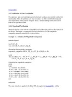
Syntax 2-1ÑSyntax for integer and real numbers
2.5.1 Integer constants
Integer constants
can be speciÞed in decimal, hexadecimal, octal, or binary format.
There are two forms to express integer constants. The Þrst form is a simple decimal number, which shall be speciÞed
as a sequence of digits
0
through
9
, optionally starting with a plus or minus unary operator. The second form speciÞes
a
sized constant
, which shall be composed of up to three tokensÑan optional size constant, a single quote followed
by a base format character, and the digits representing the value of the number.
number ::=
decimal_number
| octal_number
| binary_number
| hex_number
| real_number
decimal_number ::=
[ sign ] unsigned_number
| [ size ] decimal_base unsigned_number
binary_number ::=
[ size ] binary_base binary_digit { _ | binary_digit }
octal_number ::=
[ size ] octal_base octal_digit { _ | octal_digit }
hex_number ::=
[ size ] hex_base hex_digit { _ | hex_digit }
real_number ::=
[ sign ] unsigned_number . unsigned_number
| [ sign ] unsigned_number [ . unsigned_number ] e [ sign ] unsigned_number
| [ sign ] unsigned_number [ . unsigned_number ] E [ sign ] unsigned_number
sign ::=
+ | -
size ::=
unsigned_number
unsigned_number ::=
decimal_digit { _ | decimal_digit }
decimal_base ::=
'd | 'D
binary_base ::=
'b | 'B
octal_base ::=
'o | 'O
hex_base ::=
'h | 'H
decimal_digit ::=
0 | 1 | 2 | 3 | 4 | 5 | 6 | 7 | 8 | 9
binary_digit ::=
x | X | z | Z | 0 | 1
octal_digit ::=
x | X | z | Z | 0 | 1 | 2 | 3 | 4 | 5 | 6 | 7
hex_digit ::=
x | X | z | Z | 0 | 1 | 2 | 3 | 4 | 5 | 6 | 7 | 8 | 9 | a | b | c | d | e | f | A | B | C | D | E | F
IEEE
THE VERILOG
¨
HARDWARE DESCRIPTION LANGUAGE Std 1364-1995
Section 2 7
The Þrst token, a size constant, shall specify the size of the constant in terms of its exact number of bits. It shall be
speciÞed as an unsigned decimal number. For example, the size speciÞcation for two hexadecimal digits is 8, because
one hexadecimal digit requires 4 bits.
The second token, a base_format, shall consist of a letter specifying the base for the number, preceded by the single
quote character (Õ). Legal base speciÞcations are d, D, h, H, o, O, b, or B, for the bases decimal, hexadecimal, octal,
and binary respectively.
The use of x and z in deÞning the value of a number is case insensitive.
The single quote and the base format character shall not be separated by any white space.
The third token, an unsigned number, shall consist of digits that are legal for the speciÞed base format. The unsigned
number token shall immediately follow the base format, optionally preceded by white space. The hexadecimal digits
a to f shall be case insensitive.
Simple decimal numbers without the size and the base format shall be treated as signed integers, whereas the numbers
speciÞed with the base format shall be treated as unsigned integers.
A plus or a minus operator preceding the size constant is a sign for the constant number; the size constant does not
take a sign. A plus or minus operator between the base format and the number is an illegal syntax.
Negative numbers shall be represented in 2Õs complement form.
An x represents the unknown value in hexadecimal, octal, and binary constants. A z represents the high-impedance
value. See 3.1 for a discussion of the Verilog HDL value set. An x shall set 4 bits to unknown in the hexadecimal base,
3 bits in the octal base, and 1 bit in the binary base. Similarly, a z shall set 4 bits, 3 bits, and 1 bit, respectively, to the
high-impedance value.
If the size of the unsigned number is smaller than the size speciÞed for the constant, the unsigned number shall be
padded to the left with zeros. If the leftmost bit in the unsigned number is an x or a z, then an x or a z shall be used
to pad to the left respectively.
When used in a number, the question-mark (?) character is a Verilog HDL alternative for the z character. It sets 4
bits to the high-impedance value in hexadecimal numbers, 3 bits in octal, and 1 bit in binary. The question mark can
be used to enhance readability in cases where the high-impedance value is a donÕt-care condition. See the discussion
of casez and casex in 9.5.1. The question-mark character is also used in user-deÞned primitive state table. See 8.1.4.
The underscore character (_) shall be legal anywhere in a number except as the Þrst character. The underscore charac-
ter is ignored. This feature can be used to break up long numbers for readability purposes.
Examples:
Unsized constant numbers
Sized constant numbers
659 // is a decimal number
Õh 837FF // is a hexadecimal number
Õo7460 // is an octal number
4af // is illegal (hexadecimal format requires Õh)
IEEE
Std 1364-1995 IEEE STANDARD HARDWARE DESCRIPTION LANGUAGE BASED ON
8 Section 2
Using sign with constant numbers
Automatic left padding
Using underscore character in numbers
NOTES
1ÑA sized negative number is not sign-extended when assigned to a register data type.
2ÑEach of the three tokens for specifying a number may be macro substituted.
3ÑThe number of bits that make up an unsized number (which is a simple decimal number or a number without the size speciÞca-
tion) shall be at least 32.
2.5.2 Real constants
The real constant numbers shall be represented as described by IEEE Std 754-1985 [B1],
1
an IEEE standard for dou-
ble-precision ßoating-point numbers.
Real numbers can be speciÞed in either decimal notation (for example, 14.72) or in scientiÞc notation (for example,
39e8, which indicates 39 multiplied by 10 to the eighth power). Real numbers expressed with a decimal point shall
have at least one digit on each side of the decimal point.
Examples:
1.2
0.1
2394.26331
1
The numbers in brackets correspond to those of the bibliography in Annex H.
4Õb1001 // is a 4-bit binary number
5 ÕD 3 // is a 5-bit decimal number
3Õb01x // is a 3-bit number with the least
// significant bit unknown
12Õhx // is a 12-bit unknown number
16Õhz // is a 16-bit high-impedance number
8 Õd -6 // this is illegal syntax
-8 Õd 6 // this defines the twoÕs complement of 6,
// held in 8 bitsÑequivalent to -(8Õd 6)
reg [11:0] a, b, c, d;
initial begin
a = Õh x; // yields xxx
b = Õh 3x; // yields 03x
c = Õh z3; // yields zz3
d = Õh 0z3; // yields 0z3
end
27_195_000
16Õb0011_0101_0001_1111
32 Õh 12ab_f001
IEEE
THE VERILOG
¨
HARDWARE DESCRIPTION LANGUAGE Std 1364-1995
Section 2 9
1.2E12 (the exponent symbol can be e or E)
1.30e-2
0.1e-0
23E10
29E-2
236.123_763_e-12 (underscores are ignored)
The following are invalid forms of real numbers because they do not have at least one digit on each side of the deci-
mal point:
.12
9.
4.E3
.2e-7
2.5.3 Conversion
Real numbers shall be converted to integers by rounding the real number to the nearest integer, rather than by truncat-
ing it. Implicit conversion shall take place when a real number is assigned to an integer. The ties shall be rounded
away from zero.
Examples:
The real numbers 35.7 and 35.5 both become 36 when converted to an integer and 35.2 becomes 35.
Converting -1.5 to integer yields -2, converting 1.5 to integer yields 2.
2.6 Strings
A string is a sequence of characters enclosed by double quotes (ÒÓ) and contained on a single line. Strings used as
operands in expressions and assignments shall be treated as unsigned integer constants represented by a sequence of
8-bit ASCII values, with one 8-bit ASCII value representing one character.
2.6.1 String variable declaration
String variables are variables of register type (see 3.2) with width equal to the number of characters in the string mul-
tiplied by 8.
Example:
To store the twelve-character string ÒHello world!Ó requires a register 8 * 12, or 96 bits wide
2.6.2 String manipulation
Strings can be manipulated using the Verilog HDL operators. The value being manipulated by the operator is the
sequence of 8-bit ASCII values.
reg [8*12:1] stringvar;
initial begin
stringvar = "Hello world!";
end
IEEE
Std 1364-1995 IEEE STANDARD HARDWARE DESCRIPTION LANGUAGE BASED ON
10 Section 2
Example:
The output is:
Hello world is stored as 00000048656c6c6f20776f726c64
Hello world!!! is stored as 48656c6c6f20776f726c64212121
NOTEÑWhen a variable is larger than required to hold a value being assigned, the contents on the left are padded with zeros after
the assignment. This is consistent with the padding that occurs during assignment of nonstring values. If a string is larger than the
destination string variable, the string is truncated to the left, and the leftmost characters will be lost.
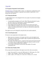
2.6.3 Special characters in strings
Certain characters can only be used in strings when preceded by an introductory character called an escape character.
Table 2-1 lists these characters in the right-hand column, with the escape sequence that represents the character in the
left-hand column.
2.7 Identifiers, keywords, and system names
An identiÞer is used to give an object a unique name so it can be referenced. An identiÞer shall be any sequence of let-
ters, digits, dollar signs ($), and underscore characters (_).
The Þrst character of an identiÞer shall not be a digit or $; it can be a letter or an underscore. IdentiÞers shall be case
sensitive.
Examples:
shiftreg_a
busa_index
error_condition
Table 2-1ÑSpecifying special characters in string
Escape
string
Character produced by
escape string
\n New line character
\t Tab character
\\ \ character
\" " character
\ddd A character speciÞed in 1Ð3 octal digits
(0 £ d £ 7)
module string_test;
reg [8*14:1] stringvar;
initial begin
stringvar = "Hello world";
$display("%s is stored as %h", stringvar,stringvar);
stringvar = {stringvar,"!!!"};
$display("%s is stored as %h", stringvar,stringvar);
end
endmodule
IEEE
THE VERILOG
¨
HARDWARE DESCRIPTION LANGUAGE Std 1364-1995
Section 2 11
merge_ab
_bus3
n$657
NOTEÑImplementations may set a limit on the maximum length of identiÞers, but they shall at least be 1024 characters. If an
identiÞer exceeds the implementation-speciÞed length limit, an error shall be reported.
2.7.1 Escaped identiÞers
Escaped identiÞers shall start with the backslash character (\) and end with white space (space, tab, newline). They
provide a means of including any of the printable ASCII characters in an identiÞer (the decimal values 33 through
126, or 21 through 7E in hexadecimal).
Neither the leading backslash character nor the terminating white space is considered to be part of the identiÞer.
Therefore, an escaped identiÞer \cpu3 is treated the same as a nonescaped identiÞer cpu3.
Examples:
\busa+index
\-clock
\***error-condition***
\net1/\net2
\{a,b}
\a*(b+c)
2.7.2 Keywords
Keywords are predeÞned nonescaped identiÞers that are used to deÞne the language constructs. A Verilog HDL key-
word preceded by an escape character is not interpreted as a keyword.
All keywords are deÞned in lowercase only. Annex B gives a list of all deÞned keywords.
2.7.3 System tasks and functions
The $ character introduces a language construct that enables development of user-deÞned tasks and functions. A
name following the $ is interpreted as a system task or a system function.
The syntax for a system task or function is given in Syntax 2-2.
Syntax 2-2ÑSyntax for system tasks and functions
The $identiÞer system task or function can be deÞned in three places:
Ñ A standard set of $identiÞer system tasks and functions, as deÞned in Section 14.
system_task_or_function ::=
$system_task_identifier [ ( list_of_arguments ) ] ;
| $system_function_identifier [ ( list_of_arguments ) ] ;
list_of_arguments ::=
argument { , [ argument ] }
argument ::=
expression
IEEE
Std 1364-1995
12 Section 2
Ñ Additional $identiÞer system tasks and functions deÞned using the PLI, as described in sections 17, 23, and
25.
Ñ Additional $identiÞer system tasks and functions deÞned by software implementations.
Any valid identiÞer, including keywords already in use in contexts other than this construct, can be used as a system
task or function name. The system tasks and functions described in Section 14 are part of this standard. Additional
system tasks and functions with the $identiÞer construct are not part of this standard.
Examples:
$display ("display a message");
$finish;
2.7.4 Compiler directives
The ` character (the ASCII value 60, called open quote or accent grave) introduces a language construct used to
implement compiler directives. The compiler behavior dictated by a compiler directive shall take effect as soon as the
compiler reads the directive. The directive shall remain in effect for the rest of the compilation unless a different com-
piler directive speciÞes otherwise. A compiler directive in one description Þle can therefore control compilation
behavior in multiple description Þles.
The `identiÞer compiler directive construct can be deÞned in two places:
Ñ A standard set of `identiÞer compiler directives deÞned in Section 16.
Ñ Additional `identiÞer compiler directives deÞned by software implementations.
Any valid identiÞer, including keywords already in use in contexts other than this construct, can be used as a compiler
directive name. The compiler directives described in Section 16 are part of this standard. Additional compiler direc-
tives with the `identiÞer construct are not part of this standard.
Example:
`define wordsize 8
IEEE
Std 1364-1995
Section 3 13
Section 3
Data types
The set of Verilog HDL data types is designed to represent the data storage and transmission elements found in digital
hardware.
3.1 Value set
The Verilog HDL value set consists of four basic values:
0 - represents a logic zero, or a false condition
1 - represents a logic one, or a true condition
x - represents an unknown logic value
z - represents a high-impedance state
The values
0
and
1
are logical complements of one another.
When the
z
value is present at the input of a gate, or when it is encountered in an expression, the effect is usually the
same as an
x
value. Notable exceptions are the metal-oxide semiconductor (MOS) primitives, which can pass the
z
value.
Almost all of the data types in the Verilog HDL store all four basic values. The exception is the
event
type (see 9.7.3),
which has no storage. All bits of vectors can be independently set to one of the four basic values.
The language includes
strength
information in addition to the basic value information for net variables. This is
described in detail in Section 7.
3.2 Nets and registers
There are two main groups of data types: the register data types and the net data types. These two groups differ in the
way that they are assigned and hold values. They also represent different hardware structures.
3.2.1 Nets
The
net
data types shall represent physical connections between structural entities, such as gates. A net shall not store
a value (except for the trireg net). Instead, its value shall be determined by the values of its drivers, such as a continu-
ous assignment or a gate. See Section 6 and Section 7 for deÞnitions of these constructs. If no driver is connected to a
net, its value shall be high-impedance (
z
) unless the net is a trireg, in which case it shall hold the previously driven
value.
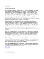
The syntax for net declarations is given in Syntax 3-1.
IEEE
Std 1364-1995 IEEE STANDARD HARDWARE DESCRIPTION LANGUAGE BASED ON
14 Section 3
Syntax 3-1ÑSyntax for net declaration
The Þrst two forms of net declaration are described in this section. The third form, called net assignment, is described
in Section 6.
3.2.2 Registers
A
register
is an abstraction of a data storage element. The keyword for the register data type is
reg
. A register shall
store a value from one assignment to the next. An assignment statement in a procedure acts as a trigger that changes
the value in the data storage element. The default initialization value for a
reg
data type shall be the unknown value,
x
.
The syntax for reg declarations is given in Syntax 3-2.
Syntax 3-2ÑSyntax for reg declaration
net_declaration ::=
net_type [ vectored | scalared ] [range] [delay3] list_of_net_identifiers ;
| trireg [ vectored | scalared ] [charge_strength] [range] [delay3]
list_of_net_identifiers ;
| net_type [ vectored | scalared ] [drive_strength] [range] [delay3]
list_of_net_decl_assignments ;
net_type ::= wire | tri | tri1 | supply0 | wand | triand | tri0 | supply1 | wor | trior
range ::= [ msb_constant_expression : lsb_constant_expression ]
drive_strength ::=
( strength0 , strength1 )
| ( strength1 , strength0 )
| ( strength0 , highz1 )
| ( strength1 , highz0 )
| ( highz1 , strength0 )
| ( highz0 , strength1 )
strength0 ::= supply0 | strong0 | pull0 | weak0
strength1 ::= supply1 | strong1 | pull1 | weak1
charge_strength ::= ( small ) | ( medium ) | ( large )
delay3 ::= # delay_value | # ( delay_value [ , delay_value [ , delay_value ] ] )
delay_value ::= unsigned_number | parameter_identifier |
constant_mintypmax_expression
list_of_net_decl_assignments ::= net_decl_assignment { , net_decl_assignment }
net_decl_assignment ::= net_identifier = expression
reg_declaration ::= reg [range] list_of_register_identifiers ;
time_declaration ::= time list_of_register_identifiers ;
integer_declaration ::= integer list_of_register_identifiers ;
real_declaration ::= real list_of_real_identifiers ;
realtime_declaration ::= realtime list_of_real_identifiers ;
list_of_register_identifiers ::= register_name { , register_name }
register_name ::=
register_identifier
| memory_identifier [ upper_limit_constant_expression :
lower_limit_constant_expression ]
IEEE
THE VERILOG
¨
HARDWARE DESCRIPTION LANGUAGE Std 1364-1995
Section 3 15
If a set of nets or registers share the same characteristics, they can be declared in the same declaration statement.
3.3 Vectors
A net or reg declaration without a range speciÞcation shall be considered 1 bit wide and is known as a scalar. Multi-
ple bit net and reg data types shall be declared by specifying a range, which is known as a vector.
3.3.1 Specifying vectors
The range speciÞcation gives addresses to the individual bits in a multibit net or register. The most signiÞcant bit
speciÞed by the msb constant expression is the left-hand value in the range and the least signiÞcant bit speciÞed by
the lsb constant expression is the right-hand value in the range.
Both msb constant expression and lsb constant expression shall be constant expressions. The msb and lsb constant
expressions can be any valueÑpositive, negative, or zero. The lsb constant expression can be a greater, equal, or
lesser value than msb constant expression.
Vector nets and registers shall obey laws of arithmetic modulo 2 to the power n (2
n
), where n is the number of bits in
the vector. Vector nets and registers shall be treated as unsigned quantities.
Examples:
wand w; // a scalar net of type ÒwandÓ
tri [15:0] busa; // a tri-state 16-bit bus
trireg (small) storeit; // a charge storage node of strength small
reg a; // a scalar register
reg[3:0] v; // a 4-bit vector register made up of (from most to
// least signiÞcant) v[3], v[2], v[1], and v[0]
reg [-1:4] b; // a 6-bit vector register
wire w1, w2; // declares two wires
reg [4:0] x, y, z; // declares three 5-bit registers
NOTES
1ÑImplementations may set a limit on the maximum length of a vector, but they will at least be 65536 (2
16
) bits.
2ÑImplementations do not have to detect overßow of integer operations.
3.3.2 Vector net accessibility
Vectored and scalared shall be optional advisory keywords to be used in vector net or reg declaration. If these key-
words are implemented, certain operations on vectors may be restricted. If the keyword vectored is used, bit and part
CAUTION
Registers can be assigned negative values, but
when a register is an operand in an expression, its
value shall be treated as an unsigned (positive)
value. For example, a minus one (-1) in a 4-bit
register shall function as the number 15 if the
register is an expression operand. See 4.1.3 for
more information on numeric conventions in
expressions.
IEEE
Std 1364-1995 IEEE STANDARD HARDWARE DESCRIPTION LANGUAGE BASED ON
16 Section 3
selects and strength speciÞcations may not be permitted, and the PLI may consider the object unexpanded. If the key-
word scalared is used, bit and part selects of the object shall be permitted, and the PLI shall consider the object
expanded.
Examples:
tri1 scalared [63:0] bus64; //a bus that will be expanded
tri vectored [31:0] data; //a bus that may or may not be expanded
3.4 Strengths
There are two types of strengths that can be speciÞed in a net declaration. They are as follows:
charge strength Shall be used when declaring a net of type trireg
drive strength Shall be used when placing a continuous assignment on a net in the same statement that declares
the net
Gate declarations can also specify a drive strength. See Section 7 for more information on gates and for information
on strengths.
3.4.1 Charge strength
The charge strength speciÞcation shall be used only with trireg nets. A trireg net shall be used to model charge stor-
age; charge strength shall specify the relative size of the capacitance indicated by one of the following keywords:
Ñ Small
Ñ Medium
Ñ Large
The default charge strength of a trireg net shall be medium.
A trireg net can model a charge storage node whose charge decays over time. The simulation time of a charge decay
shall be speciÞed in the delay speciÞcation for the trireg net (see 7.15.2).
3.4.2 Drive strength
The drive strength speciÞcation allows a continuous assignment to be placed on a net in the same statement that
declares that net. See Section 6 for more details. Net strength properties are described in detail in Section 7.
3.5 Implicit declarations
The syntax shown in 3.2 shall be used to declare nets and registers explicitly. In the absence of an explicit declaration
of a net or a register, statements for gate, user-deÞned primitive, and module instantiations shall assume an implicit
net declaration. This happens when a name is used in the terminal list of an instance of a gate, a user-deÞned primi-
tive, or a module that has not been explicitly declared previously in one of the declaration statements of the instantiat-
ing module. See 7.9.
These implicitly declared nets shall be treated as scalar nets of type wire. See Section 16 for a discussion of control of
the type for implicitly declared nets with the `default_nettype compiler directive.
3.6 Net initialization
The default initialization value for a net shall be the value z. Nets with drivers shall assume the output value of their