Astm d1633 07 (1)
Bạn đang xem bản rút gọn của tài liệu. Xem và tải ngay bản đầy đủ của tài liệu tại đây (72.31 KB, 5 trang )
Designation: D1633 − 00 (Reapproved 2007)
Standard Test Methods for
Compressive Strength of Molded Soil-Cement Cylinders1
This standard is issued under the fixed designation D1633; the number immediately following the designation indicates the year of
original adoption or, in the case of revision, the year of last revision. A number in parentheses indicates the year of last reapproval. A
superscript epsilon (´) indicates an editorial change since the last revision or reapproval.
This standard has been approved for use by agencies of the Department of Defense.
1. Scope*
combine the use of two separate sets of inch-pound units within
a single standard. As stated in 1.4.2, this standard uses the
gravitational system and does not present the slug unit for
mass. However, the use of scales or balances recording pounds
of mass (lbm) or the recording of density in lbm/ft3 shall not be
regarded as nonconformance with this standard.
1.1 This test method covers the determination of the compressive strength of soil-cement using molded cylinders as test
specimens.
1.2 Two alternative procedures are provided as follows:
1.2.1 Method A—This procedure uses a test specimen 4.0 in.
(101.6 mm) in diameter and 4.584 in. (116.4 mm) in height.
Height to diameter ratio equals 1.15. This test method made be
used only on materials with 30 % or less retained on the 3⁄4-in.
(19.0-mm) sieve. See Note 3.
1.2.2 Method B—This procedure uses a test specimen 2.8 in.
(71.1 mm) in diameter and 5.6 in. (142.2 mm) in height. Height
to diameter ratio equals 2.00. This test method is applicable to
those materials that pass the No. 4 (4.75-mm) sieve.
1.5 This standard does not purport to address all of the
safety concerns, if any, associated with its use. It is the
responsibility of the user of this standard to establish appropriate safety and health practices and determine the applicability of regulatory limitations prior to use.
2. Referenced Documents
2.1 ASTM Standards:2
C42/C42M Test Method for Obtaining and Testing Drilled
Cores and Sawed Beams of Concrete
D559 Test Methods for Wetting and Drying Compacted
Soil-Cement Mixtures
D560 Test Methods for Freezing and Thawing Compacted
Soil-Cement Mixtures
D653 Terminology Relating to Soil, Rock, and Contained
Fluids
D1632 Practice for Making and Curing Soil-Cement Compression and Flexure Test Specimens in the Laboratory
D2216 Test Methods for Laboratory Determination of Water
(Moisture) Content of Soil and Rock by Mass
D3740 Practice for Minimum Requirements for Agencies
Engaged in Testing and/or Inspection of Soil and Rock as
Used in Engineering Design and Construction
D4753 Guide for Evaluating, Selecting, and Specifying Balances and Standard Masses for Use in Soil, Rock, and
Construction Materials Testing
D6026 Practice for Using Significant Digits in Geotechnical
Data
E4 Practices for Force Verification of Testing Machines
1.3 All observed and calculated values shall conform to the
guidelines for significant digits and rounding established in
Practice D6026.
1.4 The values stated in inch-pound units are to be regarded
as standard, except as noted in 1.4.1-1.4.3. The values given in
parentheses are mathematical conversions to SI units, and are
provided for information only and are not considered standard.
1.4.1 The gravitational system of inch-pound units is used
when dealing with inch-pound units. In this system, the pound
(lbf) represents a unit of force (weight), while the unit for mass
is slugs.
1.4.2 The slug unit of mass is almost never used in
commercial practice (density, scales, balances, etc.). Therefore,
the standard unit for mass in this standard is either kilogram
(kg) or gram (g), or both. Also, the equivalent inch-pound unit
(slug) is not given.
1.4.3 It is common practice in the engineering/construction
profession in the United States to use concurrently pounds to
represent both a unit of mass (lbm) and of force (lbf). This use
combines two separate system of units, the absolute system and
the gravitational system. It is scientifically undesirable to
1
This test method is under the jurisdiction of ASTM Committee D18 on Soil and
Rock and is the direct responsibility of Subcommittee D18.15 on Stabilization With
Admixtures.
Current edition approved Feb. 1, 2007. Published March 2007. Originally
approved in 1959. Last previous edition approved in 2000 as D1633 – 00. DOI:
10.1520/D1633-00R07.
2
For referenced ASTM standards, visit the ASTM website, www.astm.org, or
contact ASTM Customer Service at For Annual Book of ASTM
Standards volume information, refer to the standard’s Document Summary page on
the ASTM website.
*A Summary of Changes section appears at the end of this standard
Copyright © ASTM International, 100 Barr Harbor Drive, PO Box C700, West Conshohocken, PA 19428-2959. United States
Copyright by ASTM Int'l (all rights reserved);
1
D1633 − 00 (2007)
3. Terminology
NOTE 2—It is desirable that the bearing faces of blocks used for
compression testing of soil-cement have a hardness of not less than 60
HRC.
3.1 For definitions of terms used in this test method, refer to
Terminology D653.
5.2 Molds and Compaction Equipment, in accordance with
Test Methods D559 or D560 for Method A; Practice D1632 for
Method B.
4. Significance and Use
4.1 Method A makes use of the same compaction equipment
and molds commonly available in soil laboratories and used for
other soil-cement tests. It is considered that Method A gives a
relative measure of strength rather than a rigorous determination of compressive strength. Because of the lesser height to
diameter ratio (1.15) of the cylinders, the compressive strength
determined by Method A will normally be greater than that for
Method B.
6. Test Specimens
6.1 Mold the test specimens as follows:
6.1.1 Method A—Specimens are 4.0 in. (101.6 mm) in
diameter and 4.584 in. (116.4 mm) in height and are molded in
accordance with Test Methods D559 or D560.
6.1.2 Method B—Specimens are 2.8 in. (71.1 mm) in
diameter and 5.6 in. (142.2 mm) in height and are molded in
accordance with Practice D1632.
4.2 Method B, because of the greater height to diameter
ratio (2.00), gives a better measure of compressive strength
from a technical viewpoint since it reduces complex stress
conditions that may occur during the shearing of Method A
specimens.
NOTE 3—These methods may be used for testing specimens of other
sizes. If the soil sample includes material retained on the 4.75-mm (No. 4)
sieve, it is recommended that Method A be used, or that larger test
specimens, 4.0 in. (101.6 mm) in diameter and 8.0 in. (203.2 mm) in
height, be molded in a manner similar to Method B.
4.3 In practice, Method A has been more commonly used
than Method B. As a result, it has been customary to evaluate
or specify compressive strength values as determined by
Method A. A factor for converting compressive strength values
based on height to diameter ratio is given in Section 8.3
6.2 Moist cure the specimens in accordance with Practice
D1632.
6.3 At the end of the moist-cure period, immerse the
specimens in water for 4 h.
NOTE 1—The agency performing this test method can be evaluated in
accordance with Practice D3740. Not withstanding statements on precision and bias contained in this test method: the precision of this test
method is dependent on the competence of the personnel performing it and
the suitability of the equipment and facilities used. Agencies that meet the
criteria of Practice D3740 are generally considered capable of competent
and objective testing. Users of this test method are cautioned that
compliance with Practice D3740 does not, in itself, ensure reliable testing.
Reliable testing depends on many factors; Practice D3740 provides a
means of evaluating some of these factors.
6.4 Remove the specimens from the water and make compression tests as soon as practicable, keeping specimens moist
by a wet burlap or blanket covering.
NOTE 4—Other conditioning procedures, such as air or oven drying,
alternate wetting and drying, or alternate freezing and thawing may be
specified after an initial moist curing period. Curing and conditioning
procedures shall be given in detail in the report.
6.5 Check the smoothness of the faces with a straightedge.
If necessary, cap the faces to meet the requirements of the
section on Capping Specimens of Practice D1632.
5. Apparatus
5.1 Compression Testing Machine—This machine may be of
any type having sufficient capacity and control to provide the
rate of loading prescribed in 7.2. It shall conform to the
requirements of Section 15 of Practices E4. The testing
machine shall be equipped with two steel bearing blocks with
hardened faces (Note 2), one of which is a spherically seated
head block that normally will bear on the upper surface of the
specimen, and the other a plain rigid block on which the
specimen will rest. The bearing faces shall be at least as large,
and preferably slightly larger, than the surface of the specimen
to which the load is applied. The bearing faces, when new, shall
not depart from a plane by more than 0.0005 in. (0.013 mm) at
any point, and they shall be maintained within a permissible
variation limit of 0.001 in. (0.02 mm). In the spherically seated
block, the diameter of the sphere shall not greatly exceed the
diameter of the specimen and the center of the sphere shall
coincide with the center of the bearing face. The movable
portion of this block shall be held closely in the spherical seat,
but the design shall be such that the bearing face can be rotated
freely and tilted through small angles in any direction.
7. Procedure
7.1 Place the lower bearing block on the table or platen of
the testing machine directly under the spherically seated
(upper) bearing block. Place the specimen on the lower bearing
block, making certain that the vertical axis of the specimen is
aligned with the center of thrust of the spherically seated block.
As this block is brought to bear on the specimen, rotate its
movable portion gently by hand so that uniform seating is
obtained.
7.2 Apply the load continuously and without shock. A screw
power testing machine, with the moving head operating at
approximately 0.05 in. (1 mm)/min when the machine is
running idle, may be used. With hydraulic machines, adjust the
loading to a constant rate within the limits of 20 6 10 psi (140
6 70 kPa)/s, depending upon the strength of the specimen.
Record the total load at failure of the test specimen to the
nearest 10 lbf (40 N).
8. Calculation
3
For additional discussion on the significance and use of compressive strength
results, see the Soil-Cement Laboratory Handbook , Chapter 4, Portland Cement
Association, Skokie, IL, 1971, pp 31 and 32.
Copyright by ASTM Int'l (all rights reserved);
8.1 Calculate the unit compressive strength of the specimen
by dividing the maximum load by the cross-sectional area.
2
D1633 − 00 (2007)
based on the test data that are available, the following may
serve as a guide as to the variability of compressive strength
test results.
10.1.1 Tests were performed in a single lab on 122 sets of
duplicate specimens molded from 21 different soil materials.
The average difference in strength on duplicate specimens was
8.1 % and the median difference was 6.2 %. These values are
expressed as the percent of the average strength of the two
specimens as follows:
NOTE 5—If desired, make allowance for the ratio of height to diameter
(h/d) by multiplying the compressive strength of Method B specimens by
the factor 1.10. This converts the strength for an h/d ratio of 2.00 to that
for the h/d ratio of 1.15 commonly used in routine testing of soil-cement
(see Section 4). This conversion is based on that given in Method
C42/C42M, which has been found applicable for soil-cement.
9. Report
9.1 The report shall include the following:
9.1.1 Specimen identification number,
9.1.2 Diameter and height, in. (mm),
9.1.3 Cross-sectional areas, in.2 (mm 2),
9.1.4 Maximum load, to the nearest 10 lbf (40 N),
9.1.5 Conversion factor for height to diameter ratio (see
Note 4), if used,
9.1.6 Compressive strength, calculated to the nearest 5 psi
(35 kPa),
9.1.7 Age of specimen, and
9.1.8 Details of curing and conditioning periods, and water
content in accordance with Test Method D2216 at the time of
test.
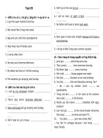
% Difference5
(1)
The distribution of the variation is shown in Fig. 1. The
data4,5 cover a wide range of cement contents and compressive
strengths.
11. Keywords
11.1 compressive strength; soil-cement; soil stabilization
4
Packard, R. G., “Alternate Measures for Measuring Freeze-Thaw and Wet-Dry
Resistance of Soil-Cement Mixtures,” Highway Research Bulletin, 353, Transportation Research Board, 1962, pp 8–41.
5
Packard, R. G., and Chapman, G. A., “Developments in Durability Testing of
Soil-Cement Mixtures,” Highway Research Record No. 36, Transportation Research
Board, 1963, pp 97–122.
10. Precision and Bias
10.1 The precision and bias of this test method have not
been established by an interlaboratory test program. However,
Copyright by ASTM Int'l (all rights reserved);
~ high value2low value!
3 100
~ high value1low value! /2
3
D1633 − 00 (2007)
FIG. 1 Distribution of Variation of Test Results for 122 Sets of Duplicate Specimens
SUMMARY OF CHANGES
In accordance with Committee D18 policy, this section identifies the location of changes to this standard since
the last edition (1996) that may impact the use of this standard.
(7) Added new footnote 4 to reference Annual Book of ASTM
Standards, Vol 04.09 and renumbered the remaining footnotes.
(8) Added new Section 3 on Terminology. Renumbered remaining sections.
(9) Added reference to Test Method D2216 in 9.1.8.
(10) Changed “crushing” to “shearing” in 4.2.
(11) Changed “moisture” to “water” in 9.1.8.
(12) Prepared new Summary of Changes.
(1) Changed title to clarify that two methods are presented.
(2) Added new sentence at the end of 1.2.1 to identify
applicable materials.
(3) Added a new sentence at the end of 1.2.2 to identify
applicable materials.
(4) Added new 1.3 to reference Practice D6026.
(5) Revised 1.4 to clarify units used in the test method.
(6) Added Terminology D653, Test Method D2216, Specification D4753, and Practice D6026 to Section 2, Referenced
Documents.
Copyright by ASTM Int'l (all rights reserved);
4
D1633 − 00 (2007)
ASTM International takes no position respecting the validity of any patent rights asserted in connection with any item mentioned
in this standard. Users of this standard are expressly advised that determination of the validity of any such patent rights, and the risk
of infringement of such rights, are entirely their own responsibility.
This standard is subject to revision at any time by the responsible technical committee and must be reviewed every five years and
if not revised, either reapproved or withdrawn. Your comments are invited either for revision of this standard or for additional standards
and should be addressed to ASTM International Headquarters. Your comments will receive careful consideration at a meeting of the
responsible technical committee, which you may attend. If you feel that your comments have not received a fair hearing you should
make your views known to the ASTM Committee on Standards, at the address shown below.
This standard is copyrighted by ASTM International, 100 Barr Harbor Drive, PO Box C700, West Conshohocken, PA 19428-2959,
United States. Individual reprints (single or multiple copies) of this standard may be obtained by contacting ASTM at the above
address or at 610-832-9585 (phone), 610-832-9555 (fax), or (e-mail); or through the ASTM website
(www.astm.org). Permission rights to photocopy the standard may also be secured from the ASTM website (www.astm.org/
COPYRIGHT/).
Copyright by ASTM Int'l (all rights reserved);
5