Hướng dẫn sử dụng Biến tần ABB ACS 400 version tiếng Việt
Bạn đang xem bản rút gọn của tài liệu. Xem và tải ngay bản đầy đủ của tài liệu tại đây (2.12 MB, 160 trang )
User’s Manual
for type ACS 400 frequency
converters from 2.2 to 37 kW
ACS 400 Frequency Converter
User’s Manual
copyright 1999 ABB Industry Oy.
3AFY 64036947 R0125 REV A
EN
Effective: 25.5.1999
ACS 400 User’s Manual iii
Safety
Warning! Only a competent electrician may install the ACS 400.
Warning! Dangerous voltages are present when mains supply is connected. Wait at least 5
minutes after disconnecting the supply before removing the cover. Measure the
voltage at DC terminals (U
c+
, U
c-
) before servicing the unit. See E.
Warning! Even when the motor is stopped there are dangerous voltages present at Power
Circuit terminals U1, V1, W1 and U2, V2, W2 and U
c+
, U
c-
.
Warning! Even when the ACS 400 is powered down, there may be dangerous external
voltages at relay terminals RO1A, RO1B, RO1C, RO2A, RO2B, RO2C.
Warning! Never attempt to repair a broken unit; contact the supplier.
Warning! The ACS 400 will start up automatically after an input voltage interruption if the
external run command is on.
Warning! When the control terminals of two or more ACS100/140/400 units are connected
in parallel, the auxiliary voltage for these control connections must be taken from
a single source which can either be one of the units or an external supply.
Warning! The heat sink may reach a high temperature (see S, Table 11).
Note! For more technical information, contact the supplier.
iv ACS 400 User’s Manual
Note about compatibility: The supplied ACS 400 frequency converter and this manual are fully
compatible with ACS-PAN-A Control Panel revision F and later. If you use a control panel with older
revision code, certain new parameter names and alarms will not be displayed properly. In this case,
refer to displayed numeric parameter values, parameter numbers and alarm codes instead.
ACS 400 User’s Manual
v
Table of Contents
Safety. . . . . . . . . . . . . . . . . . . . . . . . . . . . . . . . . . . . . . . . . iii
Installation . . . . . . . . . . . . . . . . . . . . . . . . . . . . . . . . . . . . . 1
Reference Sections. . . . . . . . . . . . . . . . . . . . . . . . . . . . . . . . . . . . . . 3
Environment for Storage, Transportation and Stationary Use . . . . 3
Dimensions (mm). . . . . . . . . . . . . . . . . . . . . . . . . . . . . . . . . . . . . . 4
Mounting the ACS 400 on the Wall . . . . . . . . . . . . . . . . . . . . . . . . 6
Removing the Cover . . . . . . . . . . . . . . . . . . . . . . . . . . . . . . . . . . . 7
Terminal Interface . . . . . . . . . . . . . . . . . . . . . . . . . . . . . . . . . . . . . 9
Attaching a Warning Sticker. . . . . . . . . . . . . . . . . . . . . . . . . . . . . . 9
Type Designation Label and Code Key . . . . . . . . . . . . . . . . . . . . 10
Motor . . . . . . . . . . . . . . . . . . . . . . . . . . . . . . . . . . . . . . . . . . . . . . 11
Floating Network . . . . . . . . . . . . . . . . . . . . . . . . . . . . . . . . . . . . . 11
Cable Connections. . . . . . . . . . . . . . . . . . . . . . . . . . . . . . . . . . . . 12
Control Terminals. . . . . . . . . . . . . . . . . . . . . . . . . . . . . . . . . . . . . 20
Connection Examples . . . . . . . . . . . . . . . . . . . . . . . . . . . . . . . . . 22
Replacing the Cover . . . . . . . . . . . . . . . . . . . . . . . . . . . . . . . . . . 23
Power On . . . . . . . . . . . . . . . . . . . . . . . . . . . . . . . . . . . . . . . . . . . 23
Environmental Information . . . . . . . . . . . . . . . . . . . . . . . . . . . . . . 23
Protection Features . . . . . . . . . . . . . . . . . . . . . . . . . . . . . . . . . . . 24
Motor Overload Protection . . . . . . . . . . . . . . . . . . . . . . . . . . . . . . 25
Loadability of ACS 400 . . . . . . . . . . . . . . . . . . . . . . . . . . . . . . . . 25
Type Series and Technical Data . . . . . . . . . . . . . . . . . . . . . . . . . 26
Product Conformity . . . . . . . . . . . . . . . . . . . . . . . . . . . . . . . . . . . 27
Accessories . . . . . . . . . . . . . . . . . . . . . . . . . . . . . . . . . . . . . . . . . 28
vi
ACS 400 User’s Manual
Programming. . . . . . . . . . . . . . . . . . . . . . . . . . . . . . . . . . . 29
ACS-PAN-A Control Panel. . . . . . . . . . . . . . . . . . . . . . . . . . . . . . . 29
Control Modes . . . . . . . . . . . . . . . . . . . . . . . . . . . . . . . . . . . . . . .29
Output Display . . . . . . . . . . . . . . . . . . . . . . . . . . . . . . . . . . . . . . .30
Menu Structure . . . . . . . . . . . . . . . . . . . . . . . . . . . . . . . . . . . . . . . 30
Setting Parameter Value . . . . . . . . . . . . . . . . . . . . . . . . . . . . . . .31
Menu Functions . . . . . . . . . . . . . . . . . . . . . . . . . . . . . . . . . . . . . . 32
LED Indicators . . . . . . . . . . . . . . . . . . . . . . . . . . . . . . . . . . . . . . .33
Diagnostic displays . . . . . . . . . . . . . . . . . . . . . . . . . . . . . . . . . . . 34
Resetting the Drive from the Control Panel . . . . . . . . . . . . . . . . . 34
Contrast Setting . . . . . . . . . . . . . . . . . . . . . . . . . . . . . . . . . . . . . .34
ACS100-PAN Control Panel . . . . . . . . . . . . . . . . . . . . . . . . . . . . . 35
Control Modes . . . . . . . . . . . . . . . . . . . . . . . . . . . . . . . . . . . . . . .35
Output Display . . . . . . . . . . . . . . . . . . . . . . . . . . . . . . . . . . . . . . .36
Menu Structure . . . . . . . . . . . . . . . . . . . . . . . . . . . . . . . . . . . . . . . 36
Setting Parameter Value . . . . . . . . . . . . . . . . . . . . . . . . . . . . . . .36
Menu Functions . . . . . . . . . . . . . . . . . . . . . . . . . . . . . . . . . . . . . . 37
Diagnostic Displays . . . . . . . . . . . . . . . . . . . . . . . . . . . . . . . . . . . 38
Resetting the Drive from the Control Panel . . . . . . . . . . . . . . . . . 38
ACS 400 Basic Parameters . . . . . . . . . . . . . . . . . . . . . . . . . . . . . . 39
Application Macros . . . . . . . . . . . . . . . . . . . . . . . . . . . . . . . . . . . . 43
Application Macro Factory (0) . . . . . . . . . . . . . . . . . . . . . . . . . . .44
Application Macro Factory (1) . . . . . . . . . . . . . . . . . . . . . . . . . . .45
Application Macro ABB Standard . . . . . . . . . . . . . . . . . . . . . . . . .46
Application Macro 3-wire . . . . . . . . . . . . . . . . . . . . . . . . . . . . . . . 47
Application Macro Alternate . . . . . . . . . . . . . . . . . . . . . . . . . . . . .48
Application Macro Motor Potentiometer . . . . . . . . . . . . . . . . . . . . 49
Application Macro Hand - Auto . . . . . . . . . . . . . . . . . . . . . . . . . .50
Application Macro PID Control . . . . . . . . . . . . . . . . . . . . . . . . . . .51
Application Macro Premagnetise . . . . . . . . . . . . . . . . . . . . . . . . .52
Application Macro PFC Control . . . . . . . . . . . . . . . . . . . . . . . . . .53
ACS 400 User’s Manual
vii
ACS 400 Complete Parameter List . . . . . . . . . . . . . . . . . . . . . . . . 55
Group 99: Start-up Data . . . . . . . . . . . . . . . . . . . . . . . . . . . . . . . 63
Group 01: Operating Data . . . . . . . . . . . . . . . . . . . . . . . . . . . . . . 64
Group 10: Command Inputs. . . . . . . . . . . . . . . . . . . . . . . . . . . . . 66
Group 11: Reference Select . . . . . . . . . . . . . . . . . . . . . . . . . . . . 68
Group 12: Constant Speeds . . . . . . . . . . . . . . . . . . . . . . . . . . . . 72
Group 13: Analogue Inputs . . . . . . . . . . . . . . . . . . . . . . . . . . . . . 73
Group 14: Relay Outputs . . . . . . . . . . . . . . . . . . . . . . . . . . . . . . . 74
Group 15: Analogue Output. . . . . . . . . . . . . . . . . . . . . . . . . . . . . 76
Group 16: System Controls . . . . . . . . . . . . . . . . . . . . . . . . . . . . . 77
Group 20: Limits. . . . . . . . . . . . . . . . . . . . . . . . . . . . . . . . . . . . . . 79
Group 21: Start/Stop . . . . . . . . . . . . . . . . . . . . . . . . . . . . . . . . . . 80
Group 22: Accel/Decel. . . . . . . . . . . . . . . . . . . . . . . . . . . . . . . . . 82
Group 25: Critical Freq. . . . . . . . . . . . . . . . . . . . . . . . . . . . . . . . . 83
Group 26: Motor Control . . . . . . . . . . . . . . . . . . . . . . . . . . . . . . . 84
Group 30: Fault Functions . . . . . . . . . . . . . . . . . . . . . . . . . . . . . . 85
Group 31: Automatic Reset . . . . . . . . . . . . . . . . . . . . . . . . . . . . . 89
Group 32: Supervision . . . . . . . . . . . . . . . . . . . . . . . . . . . . . . . . . 90
Group 33: Information . . . . . . . . . . . . . . . . . . . . . . . . . . . . . . . . . 91
Group 34: Process Variables . . . . . . . . . . . . . . . . . . . . . . . . . . . . 92
Group 40: PID Control . . . . . . . . . . . . . . . . . . . . . . . . . . . . . . . . . 94
Group 41: PID Control (2) . . . . . . . . . . . . . . . . . . . . . . . . . . . . . . 99
Group 50: Communication . . . . . . . . . . . . . . . . . . . . . . . . . . . . . 100
Group 51: Ext Comm Module . . . . . . . . . . . . . . . . . . . . . . . . . . 102
Group 52: Standard Modbus . . . . . . . . . . . . . . . . . . . . . . . . . . . 103
Group 81: PFC Control . . . . . . . . . . . . . . . . . . . . . . . . . . . . . . . 105
Standard Serial Communication. . . . . . . . . . . . . . . . . . 115
Overview . . . . . . . . . . . . . . . . . . . . . . . . . . . . . . . . . . . . . . . . . . 115
Earthing and Termination . . . . . . . . . . . . . . . . . . . . . . . . . . . . . 117
Activating Modbus Protocol . . . . . . . . . . . . . . . . . . . . . . . . . . . 118
Communication settings . . . . . . . . . . . . . . . . . . . . . . . . . . . . . . 119
Control Locations . . . . . . . . . . . . . . . . . . . . . . . . . . . . . . . . . . . 120
Output signal source selection . . . . . . . . . . . . . . . . . . . . . . . . . 121
Diagnostic Counters . . . . . . . . . . . . . . . . . . . . . . . . . . . . . . . . . 123
viii
ACS 400 User’s Manual
Communication . . . . . . . . . . . . . . . . . . . . . . . . . . . . . . . . . . . . . . 124
Introduction to Modbus . . . . . . . . . . . . . . . . . . . . . . . . . . . . . . . . 124
Register Read and Write . . . . . . . . . . . . . . . . . . . . . . . . . . . . . . 124
Register Mapping . . . . . . . . . . . . . . . . . . . . . . . . . . . . . . . . . . . .125
Exception Codes . . . . . . . . . . . . . . . . . . . . . . . . . . . . . . . . . . . .126
Function Codes . . . . . . . . . . . . . . . . . . . . . . . . . . . . . . . . . . . . .126
The Control Word and the Status Word . . . . . . . . . . . . . . . . . . .127
References . . . . . . . . . . . . . . . . . . . . . . . . . . . . . . . . . . . . . . . . . 130
Actual Values . . . . . . . . . . . . . . . . . . . . . . . . . . . . . . . . . . . . . . .131
Fault and Alarm Status . . . . . . . . . . . . . . . . . . . . . . . . . . . . . . . . 133
Diagnostics . . . . . . . . . . . . . . . . . . . . . . . . . . . . . . . . . . . 135
General . . . . . . . . . . . . . . . . . . . . . . . . . . . . . . . . . . . . . . . . . . . 135
Alarm and Fault displays. . . . . . . . . . . . . . . . . . . . . . . . . . . . . . 135
Fault Resetting . . . . . . . . . . . . . . . . . . . . . . . . . . . . . . . . . . . . . . 135
Appendix A . . . . . . . . . . . . . . . . . . . . . . . . . . . . . . . . . . . 141
Local Control vs. Remote Control . . . . . . . . . . . . . . . . . . . . . . .141
Local Control . . . . . . . . . . . . . . . . . . . . . . . . . . . . . . . . . . . . . . .141
Remote Control . . . . . . . . . . . . . . . . . . . . . . . . . . . . . . . . . . . . . 142
Internal Signal Connections for the Macros . . . . . . . . . . . . . . . . 143
Appendix B . . . . . . . . . . . . . . . . . . . . . . . . . . . . . . . . . . . 145
ACS 400 Pump and Fan Control (PFC) Macro. . . . . . . . . . . . . . 145
Introduction . . . . . . . . . . . . . . . . . . . . . . . . . . . . . . . . . . . . . . . .145
PID Controller . . . . . . . . . . . . . . . . . . . . . . . . . . . . . . . . . . . . . . . 147
Relay Outputs . . . . . . . . . . . . . . . . . . . . . . . . . . . . . . . . . . . . . . 148
Adding More I/O to ACS 400 . . . . . . . . . . . . . . . . . . . . . . . . . . . 148
Setting up NDIO modules . . . . . . . . . . . . . . . . . . . . . . . . . . . . .148
Alternation Switchgear . . . . . . . . . . . . . . . . . . . . . . . . . . . . . . . 148
ACS 400 User’s Manual 1
Installation
Study these installation instructions carefully before proceeding. Failure to observe the warnings
and instructions given may cause a malfunction or personal hazard.
Preparation before installation
To install the ACS 400 you need the following: screwdrivers, wire stripper, tape measure, 4 pieces
of ∅ 5 mm screws or nuts and bolts (depending on the mounting surface), drill.
At this point it is a good idea to check the motor parameters and write them down: supply voltage,
nominal current, nominal frequency, cos phi, nominal power and nominal speed.
Unpacking the unit
The ACS 400 comes in a box that in addition to the unit itself and this User’s Manual contains
Cable Gland Plates, Warning Stickers, an EMC Instruction and a separate Installation Guide. The
separate Installation Guide gives a summary of the installation instructions described here.
To help you marking the fixing points for installation of your ACS 400 a Wall Mounting Template is
drawn on the lid of the box. Remove the lid and save it.
Step by step instructions
The installation of the ACS 400 has been broken down into a number of steps that are listed in
Figure 1 on page 2. The steps must be carried out in the order shown. To the right of each step
reference is made to one or more Reference Sections on the following pages of this User’s Manual.
These sections give detailed information needed for the correct installation of the unit.
Warning! Before you begin read “Safety” on page iii.
2 ACS 400 User’s Manual
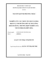
Figure 1 Step by step instructions for installing the ACS 400. The references after each step refer
to one or more of the Reference Sections on the following pages in this User’s Manual.
1
2
3
4
5
6
7
8
9
10
11
12
See A
See B, C
See D
See E, F
See E,H, I
See G,S
See K, S
See N
See M
See E, H, I,
See E, J, L
See E, H, I
CHECK the environment.
MOUNT the ACS 400 on the wall.
REMOVE the cover.
ATTACH a warning sticker
in the language of your choice.
IDENTIFY power and control terminals.
CHECK voltage supply and fuses.
CHECK I/O jumpers J1 and J2.
CHECK the motor.
CONNECT power terminals.
CONNECT control wires.
REPLACE the cover.
TURN the power on.
J, L
ACS 400 User’s Manual 3
Reference Sections
A Environment for Storage, Transportation and Stationary Use
Table 1
ACS 400 Stationary Use Storage and Transportation
in the protective package
Installation Site Altitude • 0…1000 m if P
N
and
I
2
100%
• 1000…2000 m if P
N
and
I
2
derated 1% every 100 m above
1000 m
-
Ambient Temperature •0…40°C
•max. 50°C if P
N
and
I
2
derated
to 90%
-40 +70 °C
Relative Humidity < 95% (non-condensing)
Contamination Levels
(IEC 721-3-3)
No conductive dust allowed.
The ACS 400 should be installed in clean air according to IP classification.
Cooling air must be clean, free from corrosive materials and electrically conduc-
tive dust.
In UL installations the ACS 400 should be installed in clean and dry air, free from
dripping water.
• chemical gases: Class 3C2
• solid particles: Class 3S2
Storage
• chemical gases: Class 1C2
• solid particles: Class 1S3
Transportation
• chemical gases: Class 2C2
• solid particles: Class 2S2
Atmospheric Pressure
Sinusoidal Vibration
(IEC-60068-2-6)
•2-9 Hz 0.3 mm
• 9-200 Hz 2 m/s
2
Storage
• 2-9 Hz 1.5 mm
• 9-200 Hz 5 m/s
2
Transportation
• 2-9 Hz 3.5 mm
• 9-200 Hz 10 m/s
2
Shock
(IEC 68-2-29)
not allowed
• max. 100 m/s
2
(330 ft./s
2
), 11 ms
Free Fall
not allowed
• 76 cm (30 in.), frame size R1
• 61 cm (24 in.), frame size R2
• 46 cm (18 in.), frame size R3
• 31 cm (12 in.), frame size R4
4 ACS 400 User’s Manual
B Dimensions (mm)
Units with IP 21/NEMA1 Enclosures
Figure 2 IP 21/NEMA1 enclosures.
Table 2 Dimensions of units with IP 21/NEMA1 enclosures.
* See paragraph S for frame size assignments for type codes.
Dimension Reference (mm)
Frame Size, IP 21/NEMA1 *
R1 R2 R3 R4
W 125 125 203 203
W1 98 98 160 160
W2 98 98
H 330 430 545 636
H1 318 417 528 619
H2 300 400 500 600
H3 373 473 586 686
D 209 221 248 282
D1 105 117 144 177
D2 147 159 200 233
a 5.5 5.5 6.5 6.5
b 10 10 13 13
c 5.5 6.0 8.0 8.0
d 5.5 5.5 6.5 6.5
Mass (kg) 5.5 8.5 19.0 28.6
ACS 400 User’s Manual 5
Units with IP 54/NEMA12 Enclosures
The IP 54 protection class has a different outer plastic cover compared to the IP 21. The IP 54
enclosure uses the same skeleton (inner plastic part) as the IP 21 enclosure, but an internal fan is
added to improve the cooling of the unit. This kind of structure increases the dimensions compared
to the IP 21 enclosure, but the loadability of the units with IP 54 enclosure is the same as that of the
IP 21 units.
Figure 3 IP 54/NEMA12 enclosures.
Table 3 Dimensions of units with IP 54/NEMA12 enclosures.
See paragraph S for frame size assignments for type codes.
Dimension Reference (mm)
Frame Size, IP 54/NEMA12 *
R1 R2 R3 R4
W 215 215 257 257
W1 98 98 160 160
W2 98 98
H 453 551 642 742
H1 318 417 528 619
H2 330 430 545 636
D 240 253 280 312
D1 95 107 132 145
a 5.5 5.5 6.5 6.5
b 10 10 13 14
c 5.5 5.5 8.0 8.0
d 5.5 5.5 6.5 6.5
Mass (kg) 7.2 11.2 22.3 32.3
6 ACS 400 User’s Manual
C Mounting the ACS 400 on the Wall
Warning! Before installing the ACS 400 ensure the mains supply to the installation is off.
Note! ACS 400 can be mounted onto an air duct when flange mounting option set is used.
1
Figure 4 Removing the wall mounting template.
2
Figure 5 Marking and drilling the fixing holes.
3
Figure 6 Affixing type IP 21 / NEMA1 frequency converters.
Figure 7 Affixing type IP 54 / NEMA12 frequency converters.
The lid of the packing-box shows the Wall Mounting Template.
Remove the lid from the box.
The ACS 400 should only be mounted vertically on a smooth, solid surface, free
from heat, damp, and condensation. Ensure minimum air flow gaps of 200 mm
above and below, and 30 mm on the sides of the unit.
1 Using the mounting template, mark the position of the fixing holes.
2 Drill the holes.
3 Screw in four screws or affix nuts and bolts (depending on the mounting
surface).
IP 21 / NEMA1
Position the ACS 400 onto the fixings and securely
tighten in all four corners.
Note! Only lift the ACS 400 by its metal chassis.
IP 54 / NEMA12
1 Remove the front cover, see Figure 10.
2 Remove the rubber plugs by pushing from outside.
3 Screw in the screws.
4 Replace the rubber plugs.
ACS 400 User’s Manual 7
D Removing the Cover
Figure 8 Opening the frame size R1 and R2 frequency converters of type IP 21 / NEMA1.
Figure 9 Opening the frame size R3 and R4 frequency converters of type IP 21 / NEMA1.
IP 21 / NEMA1
Opening units frame size R1 and R2 (unit
width 125 mm).
1 Remove the control panel.
2 In the control panel slot there is a little
hole. Lift the retaining lever inside.
3 Remove the cover.
1
2
3
Opening units frame size R3 and R4 (unit width 203 mm).
1 Remove the control panel if fitted.
2 Lift the retaining lever and simultaneously
pull the upper front cover slightly.
3 Lift the other retaining lever e.g. with a
screwdriver.
4 Open the upper part of the front cover and
remove it.
5 Press the retaining lever and pull.
6 Remove the lower part of the front cover.
4
1
3
2
5
6
6
8 ACS 400 User’s Manual
Figure 10 Opening type IP 54 / NEMA1
frequency converters.
IP 54 / NEMA12
1 Take the screws off.
2 Remove the front cover.
3 Remove control panel if needed.
1
2
1
1
1
1
1
ACS 400 User’s Manual 9
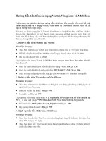
E Terminal Interface
Figure 11 Terminal interface.
F Attaching a Warning Sticker
The contents of the packing box includes warning stickers in different languages. Attach a warning
sticker in the language of your choice to the place on the inside plastic skeleton as indicated above,
in section E, ’Terminal Interface’.
X2 Panel connector
Warning sticker
X6 Connector for
X3 RS485 connector,
X1 I/O connection, see J
Analogue input jumper J1
RS485 termination
1
2
3
4
5
6
7
8
9
10
11
12
13
14
15
16
17
18
19
20
21
22
Warning! Dangerous voltage
Wait 5 minutes after
disconnecting supply
before proceeding.
See User’s Manual.
DDCS
communication
module
M A I N S M O T O R
Not used
jumpers
1
2
3
4
5
Do not connect
when unit is
powered.
see J
jumper J2
Green LED, see P
Red LED, see P
10 ACS 400 User’s Manual
G Type Designation Label and Code Key
The Type Designation Label is attached on to the heat sink.
Figure 12 ACS 400 type designation label.
The figure below shows the key for the type designation.
Figure 13 The key to the type designation code.
Serial number label is attached on the upper part of the back plate of the unit between fixing holes.
Figure 14 Serial number label.
MADE IN FINLAND
*1982800001*
3~ 380 480 V
3~ 0 - 0 U1 V
4.7 / 6.2 A
4.9 / 6.6 A
48 63 Hz
0 250Hz
Serno
For more information see ACS400 User’s Manual
N713
AC S
4
0
1 x004
3
2
AC Drive
Product Type
S = Standard product
x = OEM
ACS 400 Product Family
Input Bridge
0 = 6-pulse rectifier
Enclosure Type
1 = Wall mounted
Rated Output Power in kVA
See ACS 400 rating tables, section S, Table 11
Voltage Rating
1 = 200 240 V AC
3 = 380 480 V AC
Enclosure Class
2 = IP 21 (NEMA1)
5 = IP 54 (NEMA12)
x = Panel and manual options
Accessories
0 = Standard unit
Type
Code Ser.no.
ACS401000432
*1982800001*63996611
ACS 400 User’s Manual 11
H Motor
Check the compatibility of the motor. By default, the motor must be a three-phase induction motor,
with U
N
from 380 to 480 V and f
N
either 50 Hz or 60 Hz. If the motor values differ from these, the
group 99 parameter values must be changed.
The motor nominal current, I
N
, must not exceed the nominal output current of the ACS 400, I
2N
in
constant torque applications or I
2NSQ
in variable torque applications (See G and R).
Warning! Ensure the motor is suitable for use with the ACS 400. The ACS 400 must be
installed by a competent person. If in doubt, contact your supplier.
I Floating Network
Make sure that no excessive emission is propagated to neighbouring low voltage networks. In
some cases, the natural suppression in transformers and cables is sufficient. If in doubt, the supply
transformer with static screening between the primary and secondary windings can be used.
Note! Remove both grounding screws otherwise you may cause danger or damage the unit.
Location of the grounding screws is shown in Figure 15 and Figure 16.
Note! In IT networks do not use RFI filter. The mains becomes connected to earth through the filter
capacitors. In floating networks this may cause danger or damage the unit.
Figure 15 Removing the grounding screws from frame size R1 and R2 frequency converters.
Figure 16 Removing the grounding screws from frame size R3 and R4 frequency converters.
GND 2GND 1
GND 2GND 1
12 ACS 400 User’s Manual
J Cable Connections
IP 21 Units
A package, containing three screws and two gland plates, is included with type IP 21 (NEMA1)
ACS 400 frequency converters.
Figure 17 Gland plate for power cables (A) and for control cables (B), type IP 21 / NEMA1
frequency converters.
To open the front cover, see “Removing the Cover” on page 7.
Connect the gland plate for power cables with one screw. The threaded hole for the screw is
located in the middle of the heat sink, at the bottom end.
Figure 18 Fixing the gland plate for power cables (A), type IP 21 / NEMA1 frequency converters.
A
B
A
ACS 400 User’s Manual 13
Table 4 Cable connections.
Follow local rules for cable type and cross-sections. Use screened motor cable.
Route the motor cable away from control wires and the power supply cable to avoid
electromagnetic interference.
Figure 19 Motor cable connection for frame sizes R1 and R2 (IP 21 / NEMA1).
Note! See ACS 400 EMC instructions.
Terminal Description Note
U1, V1, W1 3~ power supply input Do not use in 1~ supply!
PE Protective Earth Follow local rules for cable cross-sections.
U2, V2, W2 Power output to motor See R.
Uc+, Uc− DC bus For optional ACS-BRK braking unit.
Motor cable shield
M A I N S M O T O R
14 ACS 400 User’s Manual
Figure 20 Motor cable connection for frame sizes R3 and R4 (IP 21 / NEMA1).
ACS 400 User’s Manual 15
The gland plate for control cables (B), see Figure 17.
Figure 21 Fixing the gland plate for control cables (B), type IP 21 / NEMA1 frequency converters.
Figure 22 Control cable connections (IP 21 / NEMA1).
Note! See ACS 400 EMC instructions.
B
A
Control cables