Báo cáo khoa học: Identification of the epitope of a monoclonal antibody that disrupts binding of human transferrin to the human transferrin receptor pptx
Bạn đang xem bản rút gọn của tài liệu. Xem và tải ngay bản đầy đủ của tài liệu tại đây (311.22 KB, 10 trang )
Identification of the epitope of a monoclonal antibody
that disrupts binding of human transferrin to the human
transferrin receptor
Evelyn M. Teh
1
, Jeff Hewitt
1
, Karen C. Ung
1
, Tanya A. M. Griffiths
1
, Vinh Nguyen
1
, Sara K. Briggs
2
,
Anne B. Mason
2
and Ross T. A. MacGillivray
1
1 Department of Biochemistry and Molecular Biology and Centre for Blood Research, University of British Columbia, Vancouver, Canada
2 Department of Biochemistry, University of Vermont, College of Medicine, Burlington, Vermont, USA
The transferrins (TF) are a group of metal-binding pro-
teins that are involved in iron homeostasis [1]. Struc-
tural studies have revealed that the TFs consist of a
single polypeptide chain of M
r
80000 that folds into
two halves called the N- and C-lobes, each of approxi-
mately 330 amino acids. In human transferrin (hTF),
the lobes are connected by a short peptide of seven resi-
dues. Each lobe itself can be further subdivided into
two domains separated by a deep cleft that forms the
iron-binding site [2–4]. The N1 domain (residues 1–93
and 247–315), C1 domain (residues 340–424 and 583–
679), N2 domain (residues 94–246) and C2 domain (res-
idues 425–582) are composed of a similar a ⁄ b fold in
which a number of helices are packed against a central
mixed b-sheet [5]. These domains are connected by two
extended b-strands running antiparallel to each other
forming a ‘hinge’ that allows the domains to open and
close upon metal binding and release [6]. Iron is bound
in a distorted octahedral coordination involving four
amino acid ligands and two oxygen atoms from a
synergistically bound carbonate ion.
The iron–TF complex enters the cell by binding with
high affinity (K
d
1–10 nm) to a specific TF receptor
(TFR), a type-II membrane protein consisting of two
identical M
r
95000 subunits covalently linked by two
disulfide bonds [7]. The N-terminal region of the recep-
tor projects into the cytoplasm of the cell and is joined
via the transmembrane region to a 671-residue extra-
cellular domain that binds TF. A soluble form of the
receptor can be released by trypsin [8] or produced by
recombinant techniques [9,10]. Although these forms
lack the two disulfide linkages, strong noncovalent
Keywords
transferrin C-lobe; transferrin–transferrin
receptor interaction; epitope mapping;
monoclonal antibody
Correspondence
R.T.A. MacGillivray, Department of
Biochemistry and Molecular Biology and
Centre for Blood Research, University of
British Columbia, Vancouver, BC, V6T 1Z3,
Canada
Tel: +1 604 822 3027
Fax: +1 604 822 4364
E-mail:
(Received 9 July 2005, revised 7 October
2005, accepted 19 October 2005)
doi:10.1111/j.1742-4658.2005.05028.x
The molecular basis of the transferrin (TF)–transferrin receptor (TFR)
interaction is not known. The C-lobe of TF is required to facilitate binding
to the TFR and both the N- and C-lobes are necessary for maximal bind-
ing. Several mAb have been raised against human transferrin (hTF). One
of these, designated F11, is specific to the C-lobe of hTF and does not
recognize mouse or pig TF. Furthermore, mAb F11 inhibits the binding of
TF to TFR on HeLa cells. To map the epitope for mAb F11, constructs
spanning various regions of hTF were expressed as glutathione S-trans-
ferase (GST) fusion proteins in Escherichia coli. The recombinant fusion
proteins were analysed in an iterative fashion by immunoblotting using
mAb F11 as the probe. This process resulted in the localization of the F11
epitope to the C1 domain (residues 365–401) of hTF. Subsequent computer
modelling suggested that the epitope is probably restricted to a surface
patch of hTF consisting of residues 365–385. Mutagenesis of the F11
epitope of hTF to the sequence of either mouse or pig TF confirmed the
identity of the epitope as immunoreactivity was diminished or lost. In
agreement with other studies, these epitope mapping studies support a role
for residues in the C1 domain of hTF in receptor binding.
Abbreviations
TF, transferrin; TFR, transferrin receptor; GST, glutathione S-transferase; hTF(R), human transferrin (receptor).
6344 FEBS Journal 272 (2005) 6344–6353 ª 2005 The Authors Journal compilation ª 2005 FEBS
interactions still result in dimer formation. The crystal
structure for the recombinant form of the soluble TFR
has been determined [9], and a higher resolution struc-
ture of the soluble TFR in a complex with the hemo-
chromatosis gene product HFE has also been described
[11]. These structures reveal that the TFR ectodomain
consists of three subdomains: a helical domain respon-
sible for dimerization, a protease-like domain and an
apical domain. Studies with chimeric receptors made
from regions of both the human and chicken TFR sug-
gest that TF binds to the helical domain of the TFR
[12] with at least part of the hTF binding site localized
specifically to residues 646–648 in the TFR [13,14].
These studies are based on the long-standing observa-
tion that hTF does not bind to chicken TFR and, recip-
rocally, ovotransferrin (oTF) does not bind to the
hTFR. The observation that the HFE protein and hTF
bind to the same or closely overlapping sites [14] adds
further support for the role of the helical domain of the
TFR in binding to TF since most of the residues that
bind to HFE reside in this domain.
Identification of the specific regions of TF that inter-
act with the TFR has remained more elusive and con-
troversial. Although there is some disagreement in the
literature regarding the exact region(s) of TF involved
in TFR binding, it is generally accepted that both lobes
of TF are required for maximal binding [15–17]. A par-
ticularly intriguing aspect of the interaction of TF with
the TFR is its pH dependence. At pH 7.4, diferric TF
preferentially binds to TFR. At pH 5.6 (a value within
the putative pH range of endosomes), iron free or apo-
TF preferentially binds to TFR. Since a substantial and
well-documented conformational change (60° opening
and twisting [18]), accompanies the release of iron from
TF, a compensating change in the TFR conformation
might also be expected. In fact, the TFR has been
shown to play a role in iron release from TF in a pH
sensitive manner [19–21]. A structure of the hTF–hTFR
complex was recently determined with cryo-electron
microscopy [22]. In this model, the transferrin N-lobe is
situated between the membrane and the TFR ectodo-
main while the C-lobe binds to the TFR helical domain
through side chain contacts of the C1 domain. More
detailed information about the molecular interactions
between the C-lobe and the TFR was obtained by
hydroxyl radical-mediated protein footprinting and
mass spectrometry [23]. In these experiments, specific
C-lobe sequences (residues 381–401, 415–433 and
457–470) were protected against oxidation and thus
proposed to be involved in receptor binding.
Another approach to determine the regions of TF
that are critical to receptor binding is the production
of specific monoclonal antibodies (mAb) that can be
tested for their ability to block such binding. Mason
and Woodworth characterized seven high affinity anti-
bodies that recognized at least four different epitopes
in hTF [24]. Three of the mAbs recognized unique epi-
topes in the N-lobe and two (designated E8 and F11)
recognized the same or a closely overlapping epitope
in the C-lobe. Interestingly, the C-lobe mAbs bound
with high affinity to hTF but did not recognize six
other mammalian TFs. Further studies clearly demon-
strated that the C-lobe mAbs recognized both the
reduced and nonreduced forms of hTF indicating that
the epitope is mainly sequential rather than conforma-
tional [24]. It was also noted, however, that the inter-
action was sensitive to the presence or absence of iron
with a two-fold higher affinity for iron loaded TF
compared to apo-TF. This observation suggested that
the epitope may also have a conformational compo-
nent as binding of iron by either lobe of TF is accom-
panied by a significant conformational change.
The current study describes the localization of the
mAb F11 epitope to the C-lobe of hTF, specifically to
residues 365–401 that are located in the C1 domain. In
particular, these results implicate this region in the
binding of hTF to TFR.
Results
TFR binding studies
The results of a study designed to determine the ability
of selected mAbs to block binding of a subsaturating
amount of radioiodinated hTF to TFR on HeLa cells
are presented in Fig. 1. The three mAbs specific to the
N-lobe demonstrated variable degrees of blocking.
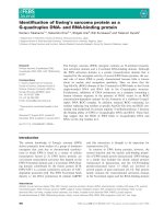
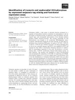
Fig. 1. mAb mediated inhibition of hTF binding to TFR on HeLa
cells.
125
I-labelled hTF was incubated with HeLa cells in the pres-
ence of increasing amounts of mAb and the resultant binding
expressed as the percentage of the binding in the absence of mAb.
The mAbs used were: aHT + N
1,
aHT + N
2,
HTF.14, F11 and E8
[24].
E. M. Teh et al. Transferrin–transferrin receptor interaction
FEBS Journal 272 (2005) 6344–6353 ª 2005 The Authors Journal compilation ª 2005 FEBS 6345
Two of the antibodies (aHT + N
1
and aHT + N
2
)
partially blocked binding whereas the third antibody
(HTF.14) blocked virtually all binding to TFR. The
antibodies to the C-lobe (F11 and E8, which share the
same or a very similar epitope [24]) inhibited virtually
all binding of hTF to TFR. Also, treatment of hTF
with biotin resulted in a preparation of biotinylated
hTF that was not recognized by the mAb F11 (data
not shown). As biotin binds to lysyl residues, this
result suggests that a lysyl residue may be involved in
antibody–epitope recognition.
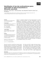
Analysis of IPTG-induced fusion protein expression
To identify the epitope for mAb F11, several fusion
plasmids comprised of GST and various regions of TF
were constructed (Fig. 2, see Experimental procedures).
These constructs were expressed in Escherichia coli and
the immunoreactivity of the recombinant fusion pro-
teins to mAb F11 in the uninduced and IPTG-induced
states was analysed by Western blot. An anti-GST
serum was used to verify the production of the GST
fusion proteins. Figure 3A and Fig. 4A are immuno-
blots of the bacterial lysates of various GST–hTF
fusions visualized with the anti-GST serum. The pres-
ence of a 29-kDa band in the uninduced lanes of pGEX
4T3 (Fig. 3A, lane 1; Fig. 4A, lane 4) is probably due
to low levels of constitutive expression from the pGEX
promoter. Nevertheless, induction leads to a substantial
increase in expression (Fig. 3A, lane 2; Fig. 4A, lane 5).
Based on the intensity of the bands from equal amounts
of cell lysate, both the N- and C-lobe GST fusion pro-
teins were expressed at similar levels (Fig. 3A, lanes 4
and 6). As expected, full-length hTF is not recognized
by the anti-GST serum (Fig. 4A, lane 1). The other
constructs (hTF-5 to hTF-8 and hTF-5A to hTF-5F)
were also successfully expressed and migrated at a mass
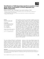
Fig. 2. GST–TF fusion proteins used for western blot analysis. The
fusion proteins consisted of GST (white bar) joined to regions of
the hTF N-lobe (grey bar) and C-lobe (black bar). The encompassing
residues of hTF in each of the GST fusion proteins are labelled
above the bars.
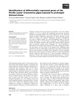
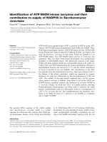
A
B
Fig. 3. Western blot analysis of GST–hTF fusion proteins. (A) West-
ern blot analysis using an anti-GST serum before (–) and after (+)
induction of the fusion protein. The following expression plasmids
were used: (lanes 1–2) pGEX4T3; (lanes 3–4) hTF N-lobe; (lanes 5–6)
hTF C-lobe; (lanes 7–8) hTF-5; (lanes 9–10) hTF-6; (lanes 11–12)
hTF-7; (lanes 13–14) hTF-8. (B) Western blot analysis using the mAb
F11 after induction of the fusion protein. The following expression
plasmids were used: (lane 1) pGEX4T3; (lane 2) hTF; (lane 3) hTF
N-lobe; (lane 4) hTF C-lobe; (lane 5) hTF-5; (lane 6) hTF-6; (lane 7)
hTF-7; (Lane 8) hTF-8.
Transferrin–transferrin receptor interaction E. M. Teh et al.
6346 FEBS Journal 272 (2005) 6344–6353 ª 2005 The Authors Journal compilation ª 2005 FEBS
consistent with their predicted fusion protein composi-
tions (Fig. 3A, lanes 8, 10, 12 and 14; Fig. 4A, lanes 7,
9, 11, 13, 15 and 17).
Epitope mapping for mAb F11
Western blot analysis of the different C-lobe fragments
with the mAb F11 allowed the determination of the
specific region of the C-lobe containing the epitope
(Fig. 3B). Full-length hTF was used as a positive con-
trol and a bacterial lysate from E. coli transformed with
pGEX 4T3 was used as a negative control. In agreement
with previous studies, only full-length hTF (lane 2) and
the hTF C-lobe (lane 4) fusion protein showed reactivity
with the antibody [24]. Following division of the C-lobe
into four fragments of approximately 100 residues each,
only the hTF-5 fusion protein (lane 5) was positive. This
fragment encompasses residues 342–440 of hTF and
maps to the amino terminus of the C-lobe contained lar-
gely within the C1 domain.
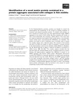
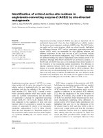
To further delineate the region recognized by the
mAb F11, additional pGEX 4T3 constructs were made
containing deletions from the carboxy-terminal region
of the hTF-5 fragment. These constructs (designated
hTF-5A to 5F) encompassed residues 342–420. As
shown in Fig. 4B, a positive signal was observed with
constructs hTF-5B, 5C and 5D (lanes 8, 10, and 12)
blotted with the mAb F11 while construct 5A (lane 6)
gave only a weak signal. Even at higher concentrations
of the hTF-5A bacterial lysates, the intensity of the
immunoreactive band did not increase relative to con-
structs 5B, 5C and 5D (data not shown). These results
suggest that hTF-5A may contain only part of the F11
epitope. The absence of reactivity with the 5E and 5F
constructs indicates that these constructs did not con-
tain the epitope for the mAb F11. Based on these
results, the epitope for the mAb F11 was localized to a
region within residues 365–401.
A nonspecific band at 66 kDa was observed in all
the lanes for the mAb F11 Western blots (Fig. 4B),
A
B
Fig. 4. Western blot analysis of GST–hTF-5 fusion proteins. (A) Western blot analysis using an anti-GST serum before (–) and after (+) induc-
tion of the fusion protein. The following expression plasmids were used: (lane 1) hTF; (lanes 2–3) hTF C-lobe; (lanes 4–5) pGEX4T3; (lanes
6–7) hTF-5 A; (lanes 8–9) hTF-5B; (lanes 10–11) hTF-5C; (lanes 12–13) hTF-5D; (lanes 14–15) hTF-5E; (lanes 16–17) hTF-5F. (B) Western blot
analysis using the mAb F11 before (–) and after (+) induction of the fusion protein. The following expression plasmids were used: (lanes
1–2) pGEX4T3; (lanes 3–4) hTF C-lobe; (lanes 5–6) hTF-5 A; (lanes 7–8) hTF-5B; (lanes 9–10) hTF-5C; (lanes 11–12) hTF-5D; (lanes 13–14)
hTF-5E; (lanes 15–16) hTF-5F.
E. M. Teh et al. Transferrin–transferrin receptor interaction
FEBS Journal 272 (2005) 6344–6353 ª 2005 The Authors Journal compilation ª 2005 FEBS 6347
including the pGEX 4T3 control. Furthermore, the
hTF C-lobe, hTF-5C and hTF-5D (lanes 4, 10 and 12)
samples had additional bands at lower molecular
weights not seen in the pGEX 4T3 control (lane 2).
The intensities of these bands corresponded to the pos-
itive reactivity of the target protein and may therefore
have been degradation products of the truncated pro-
tein. The sensitivity of the anti-GST serum to detect
lower concentrations of the target protein is not as
great as that of the mAb F11; therefore, it is not sur-
prising that the corresponding bands are not seen in
the anti-GST blots. As hTF-5E and 5F fusion proteins
are short, 23 and 17 amino acid residues, respectively,
it could be argued that the absence of positive signal
be attributed to protein degradation. However, the
GST moiety was detected with the anti-GST serum
(Fig. 4A, lanes 15 and 17) and showed the appropri-
ate, slight increase in molecular mass corresponding
to the theoretical GST C-lobe fusion product, so this
possibility seems unlikely.
Studies with synthetic peptide
To investigate the identity of the F11 epitope further,
a synthetic peptide having a short sequence
KIECVSAETTEDCI (amino acid residues 365–378 of
the C-lobe of hTF) from the positive fusion protein
hTF-5B (Fig. 4B, lane 8) was synthesized for use in a
competitive immunoassay. Unfortunately, the peptide
was insoluble in both reducing and nonreducing aque-
ous solutions and this precluded its use in further
studies. An alternative approach was used to verify the
localized epitope.
Crossreactivity of the mAb F11
In previous studies by Mason and Woodworth [24],
mAb F11 did not recognize six other mammalian TFs
nor oTF. A protein sequence alignment was performed
and upon comparison of the amino acid sequences in a
region of the putative F11 epitope (residues 365–378,
hTF numbering), it was determined that all TFs ana-
lyzed had at least one amino acid difference (Table 1).
To confirm the mAb F11 epitope, the hTF-5D con-
struct, which showed the greatest reactivity with the
mAb F11, was mutated at two different residues to
mimic the sequence of either pig (T373N) or mouse
(V369E) TF. Figure 5A shows expression of the con-
structs as detected by the anti-GST serum. Both the
hTF-5D T373N (lane 3) and hTF-5D V369E (lane 5)
constructs were expressed at a similar level to hTF-5D
(lane 1). Neither the hTF-5D T373N (Fig. 5B, lane 4),
Table 1. Sequence alignment of TF family members. The alignments were made with BLOSUM 62 score tables with default settings; amino
acid numbering is for hTF. Residues that are identical to hTF at the equivalent position are shown by ’ ’.
Residue # 365 366 367 368 369 370 371 372 373 374 375 376 377 378
hTF KI ECVSAETTEDCI
Pig TF N
Mouse TF E
Rat TF Q E S
Rabbit TF L E P
Horse TF N E Q S
Bovine TF A E T N E
Chicken oTF D V T V V D E K
A
B
Fig. 5. Western blot analysis of the modified hTF-5D GST fusion
proteins. (A) Anti-GST blot of the hTF-5D and the modified con-
structs before (–) and after (+) induction with IPTG. The following
expression plasmids were used: (lane 1–2) hTF-5D; (lane 3–4) hTF-
5D T373N; (lane 5–6) hTF-5D V369E. (B) The F11 blot of hTF-5D
and the modified hTF-5D constructs before (–) and after (+) induc-
tion of the fusion protein. The following expression plasmids were
used: (lane 1–2) hTF-5D; (lane 3–4) hTF-5D T373N; (lane 5–6)
hTF-5D V369E. The arrow denotes the position of the GST-5D
constructs.
Transferrin–transferrin receptor interaction E. M. Teh et al.
6348 FEBS Journal 272 (2005) 6344–6353 ª 2005 The Authors Journal compilation ª 2005 FEBS
which resembles the pig TF sequence, nor the hTF-5D
V369E (Fig. 5B, lane 6) representing the mouse
sequence in the putative epitope region, had a positive
immunoreaction with mAb F11 (compare to hTF-5D,
Fig. 5B, lane 2). This result is consistent with the
earlier mapping of the mAb F11 to a sequence in the
C-lobe of human TF while showing no cross-reactivity
with pig and mouse TF [24].
Discussion
The present study establishes that the epitope of the
F11 antibody is in the C-lobe of hTF, specifically
within residues 365–401 of the C1 domain. Further-
more, binding of the F11 antibody to hTF inhibits
binding to TFR (Fig. 1). The residues of TF that are
involved in receptor binding have remained elusive,
but it has been documented that the C-lobe binds to
TFR with a much higher affinity than the N-lobe and
mixing of both lobes increases the binding further [15].
Thus, it has been suggested that specific C-lobe resi-
dues are critical for establishing contacts with TFR
while the N-lobe residues are required for maximal
binding [22]. Our goal was to use an epitope mapping
study with an antibody known to inhibit binding of
hTF to TFR to delineate the residues that comprise
the antibody binding site and thus, by extension, the
TFR binding site.
The E. coli pGEX expression system allows for the
production of GST fusion proteins and was used to
express the C-lobe of hTF and partial fragments of the
C-lobe. Earlier studies have shown that glycosylation
of hTF is not important for protein expression [25]
and the expression of functional forms of recombinant
full-length, N-lobe and C-lobe of human transferrin in
E. coli has been demonstrated [26–28]. Thus, a pro-
karyotic host was chosen for this study as it provided
a simple and cost effective method for analysis with
the denaturing conditions used. Although expression
of the hTF C-lobe has been shown in various systems,
levels are consistently lower than those of the recom-
binant N-lobe in eukaryotic cells [1,25,27,28]. It
remains unclear why expression of the isolated C-lobe
yields low protein production but the large number of
disulfide bonds (11 in total) present in the C-lobe is
certainly a factor [17]. Another approach for obtaining
the C-lobe was recently reported in which a factor Xa
cleavage site was introduced into the connecting bridge
region of the higher expressing full-length TF [17]. The
two lobes were subsequently separated after treatment
of the full-length TF with factor Xa. In the current
study, we have also obtained expression of the C-lobe
of TF although we have not determined whether it
assumes a native conformation. It is possible that the
29-kDa GST moiety in this system provides some sta-
bilization.
Immunoscreening of the GST-hTF C-lobe fragments
by Western blot analysis was used to identify the mAb
F11 epitope, which was localized to residues 365–401
in the amino-terminal region of the hTF C-lobe. Con-
firmation for the identification of this particular region
as the mAb F11 epitope came from two observations.
First, we have shown that a single amino acid substitu-
tion in either one of two residues between positions
365 and 378 abolished the immunoreactivity to mAb
F11 (Fig. 5B). The two mutations in this region corres-
pond to the amino acid sequences of either mouse
(V369E) or pig (T373N) TF, neither of which is recog-
nized by the mAb F11. Substitution of a negatively
charged glutamyl residue for the hydrophobic valyl
residue observed in the mouse sequence abolished all
reactivity to the F11 antibody. Furthermore, the fairly
conservative T373N substitution observed in the pig
TF sequence also resulted in loss of immunoreactivity.
An M382V substitution in mouse and pig TF could
also contribute to the lack of cross reactivity between
species. Antibodies can be exquisitely sensitive to such
small changes in sequence [29]. These results provide
strong support that the epitope is located within resi-
dues 365–401. Second, treatment of hTF with biotin
resulted in a preparation of biotinylated hTF that was
not recognized by the mAb F11. Biotin binds to lysyl
residues and there are lysyl residues at positions 365,
380, and 401. According to the crystal structure of
hTF [30], K365 and K380 are located on the surface
of the C-lobe and may be attractive targets for the
immune system. The crystal structure of hTF also
shows that residues 386–401 are buried in the interior
of the protein with K401 actually appearing on the
opposite face of the protein from the majority of resi-
dues in the F11 epitope [30]. Assuming that the F11
antibody is binding to surface residues, it is likely that
the epitope is restricted to residues 365–385 of the hTF
C-lobe.
The mAb F11 blocked binding of hTF to the TFR;
this suggests the antibody epitope contains residues
that are located in the vicinity of the ligand–receptor
interaction. The ability of the F11 antibody to block
such binding is likely caused by steric interference.
Examination of the recently published pig TF structure
shows that the residues in the pig TF sequence equival-
ent to 365–372 make up a b-strand [31] and Asn373 of
pig TF (Table 1, Thr373 in hTF) lies in a loop follow-
ing this strand. As shown in Fig. 6, the putative F11
epitope described in this work maps to a surface on
the C1 domain of hTF. A peptide footprinting study
E. M. Teh et al. Transferrin–transferrin receptor interaction
FEBS Journal 272 (2005) 6344–6353 ª 2005 The Authors Journal compilation ª 2005 FEBS 6349
by Liu and colleagues [23] also predicted the amino
acids that comprise part of the F11 epitope to be
involved in TFR binding. In their study, oxidative
modification of various peptides in the C-lobe of hTF
was monitored. Peptides that were oxidized while the
C-lobe was isolated but were protected from oxidative
modification after the C-lobe had associated with the
TFR were suggested to be involved in hTF–TFR
association. A region of hTF we have proposed to be
involved in TFR binding was shown to be protected
from oxidative modification and was thus proposed to
undergo a conformational change upon hTF–TFR
binding. An elegant study by Cheng et al. [22] des-
cribes the structure of hTF complexed with hTFR as
determined by cryo-electron microscopy. The authors
proposed that a positively charged patch of TFR con-
taining many basic residues interacts with a comple-
mentary negative patch of hTF containing acidic
residues. The F11 epitope described in this study con-
tains seven acidic residues, two of which were pro-
posed to interact with the TFR (Glu367 and Glu372)
[22]. It is possible that the F11 epitope is not within
the binding site of TF for the receptor but that binding
of the antibody leads to steric hindrance or conforma-
tional changes that alter the binding site. However, the
agreement of the F11 epitope with the studies of
Cheng [22] and Liu [23] argues against this idea.
It has been proposed from modelling studies that
both the C1 and N1 domains anchor hTF to the TFR
[9]. In contrast, the C2 and N2 domains are thought
to be the main source of movement about the hinge in
response to iron release [9]. Unfortunately, there is
no structure available for the iron free form of any
mammalian serum TF that would allow assessment of
conformational change in this region in response
to iron release. One other interesting and potentially
relevant observation is that human, mouse, rat and
rabbit serum TFs all have an extra disulfide bond com-
prised of residues 137 and 331 (human numbering)
which restricts access to the hinge region and could
have an impact on the stability of the N1 and C1
regions. Bovine, pig and horse TF lack this extra disul-
fide bond possibly giving them greater flexibility. Addi-
tionally, it may be significant that the epitope is
located on the opposite face from the glycosylation
site, which has been shown to have no role in receptor
binding [25].
Human, pig, rabbit and horse TF bind to human
TFR, whereas bovine TF binds very poorly and
chicken oTF does not bind at all. This either means
that the antibody is more discriminating than the
receptor in recognition and ⁄ or there are multiple
receptor binding sites that contribute to the overall
binding. Until a crystal structure of the TF–TFR com-
plex resolves these issues, the current studies highlight
an area of hTF that is a strong candidate for partici-
pation in the interaction with the receptor.
Experimental procedures
Materials
E. coli strain DH5aF¢ and pBluescript SK
–
were from
Stratagene (La Jolla, CA). E. coli strain BL21 (DE3) was
from Novagen (San Diego, CA). The vector pGEX 4T3
used for the expression of the GST fusion proteins, the
GST Detection Module (including anti-GST serum) and
the chemiluminescence detection kit were from GE Health-
care (Piscataway, NJ). Isopropyl-b-D-thiogalactopyranoside
(IPTG) and BSA were from the Sigma Chemical Company
(Oakville, ON) as were horseradish peroxidase-conjugated
immunoglobulins. Human transferrin was from Roche
Applied Science (Laval, QC). Immunopure NHS-LC-Biotin
and Immunopure avidin-horseradish peroxidase were from
Pierce (Rockford, IL). The TMB Microwell peroxidase sub-
strate system was from Kirkegaard and Perry Laboratories
(Gaithersburg, MD). All other chemicals and reagents were
of analytical grade. Milli-Q water was used to prepare all
solutions. The F11 and E8 antibodies were a generous gift
from Dr James D. Cook and coworkers at the University
of Kansas Medical Center in Kansas City, KS.
TFR binding studies
To examine the ability of various monoclonal antibodies
to block binding of hTF to the hTFR on HeLa cells, a
limiting amount of
125
I-labelled diferric hTF (20 pmol) was
A
B
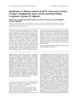
Fig. 6. Location of the mAb F11 epitope in hTF. The C1 and N1
domains are highlighted in light grey; C2 and N2 domains are col-
oured dark grey. The F11 epitope (residues 365–401), which is in
close proximity to the labelled bridge region, is shown in red. The
two views are rotated 90° to each other. The coordinates of the
monoferric hTF crystal structure were provided by Dr H. Zuccola
[30].
Transferrin–transferrin receptor interaction E. M. Teh et al.
6350 FEBS Journal 272 (2005) 6344–6353 ª 2005 The Authors Journal compilation ª 2005 FEBS
preincubated with increasing amounts of each antibody
(0–80 pmol) at room temperature for 30 min in a total
volume of 100 l L. At this time, 300 lL of HeLa cells
(1.4 · 10
6
cells) that had been incubated at 37 °C for
20 min with 10 mm NH
4
Cl to inhibit iron removal from
the hTF in the subsequent incubations was added to Omni-
vials containing the radioiodinated TF and the mAbs. After
incubation at 37 °C for 30 min with gentle shaking, por-
tions of the cell suspension (three portions, 80 lL each)
were washed and assayed as described in detail [15,25]. The
results are expressed as the percentage of binding of radio-
iodinated hTF to HeLa cells in the absence of added anti-
body.
Cloning of hTF fragments
The hTF cDNA cloned into pUC18 was used as a template
for the generation of the hTF N-lobe, hTF C-lobe and four
subfragments of the hTF C-lobe designated 5, 6, 7 and 8.
Primers used in the PCR amplifications are listed in
Table 2. PCR amplifications were performed with VENT
polymerase (New England Biolabs, Beverly, MA) in a Per-
kin Elmer Cetus DNA Thermal Cycler 480 and consisted
of 30 cycles of denaturation at 94 ° C for 1 min, annealing
at 54 °C for 1 min and extension at 72 °C for 1 min fol-
lowed by a 10-min final extension at 72 °C. Using specific
flanking restriction sites listed in Table 2, the PCR products
were cloned into pBluescript SK– vector and transformed
into E. coli DH5aF¢. To confirm the expected sequences of
the constructs and to ensure the absence of mutations
introduced during the PCR steps, DNA sequence analysis
of positive clones was performed using an ABI Prism
Model 310 Genetic Analysis DNA Sequencer (Dr Ivan
Sadowski, University of British Columbia, BC).
Cloning of hTF fragments into the pGEX 4T3
vector
The hTF fragments were subcloned into the pGEX 4T3
vector for the expression of GST fusion proteins. Briefly,
the pBluescript–hTF clones were digested with either XhoI
and NotI (hTF N-lobe) or BamHI and EcoRI (hTF
C-lobe), purified and ligated into the 3¢ end of the GST
sequence in the pGEX 4T3 expression vector. The pGEX
4T3 constructs were transformed into E. coli strain BL21
(DE3) (Novagen, Madison, WI) and positive clones were
selected by PCR screening and verified by both multiple
restriction digests and DNA sequence analysis.
Additional pGEX 4T3-hTF-5 based recombinant plas-
mids were constructed that contained subfragments of hTF-
5 designated 5A to 5F. These subclones were obtained by
PCR amplification using the pGEX 4T3 hTF-5 as a tem-
plate, the hTF-5 forward primer and a new reverse primer
(Table 2). PCR conditions were 30 cycles of denaturation
Table 2. Oligonucleotide primers used to generate the GST–hTF fusion proteins. Synthetic oligonucleotide primers were used to amplify
regions of the N- and C-lobes of hTF and clone into the pGEX 4T3 plasmid.
pGEX 4T3 clones Primer sequence (5¢fi3¢)
a
Cloning site
hTF ⁄ N-lobe AAA
CTCGAGAGTCCCTGATAAAACTGTGAGATG XhoI ⁄ NotI
AAA
GCGGCCGCTTAGCATGTGCCTTCCCGTAG
hTF ⁄ C-lobe AAA
GGATCCTGCAAGCCTGTGAAGTGG BamHI ⁄ EcoRI
AAA
GAATTCATTAAGGTCTACGGAAAGTGCAGG
hTF5
b
AAAGGATCCATGAAGTGGTGTGCGCTGAG BamHI ⁄ EcoRI
AAA
GAATTCTTACAGGTGAGGTCAGAAGCTGATT
hTF6 AAA
GGATCCAATTTTGCTGTAGCAGTGGTGAA BamHI ⁄ EcoRI
AAA
GAATTCTTAACCTGAAAGCGCCTGTGTAG
hTF7 AAA
GGATCCCCCAACAACAAAGAGGGATACT BamHI ⁄ EcoRI
AAA
GAATTCTTAGGTGCTGCTGTTGACGTAATAT
hTF8 AAA
GGATCCAAGGAAGCTTGCGTCCACAAGATA BamHI ⁄ EcoRI
AAA
GAATTCTTAGGCAGCCCTACCTCTGAGATTTT
hTF5A
c
AAAGAATTCTTAGGTGGTCTCTGCTGATACACACTC BamHI ⁄ EcoRI
hTF5B
c
AAAGAATTCTTAATGCAGTCTTCGGTGGTCTCT BamHI ⁄ EcoRI
hTF5C
c
AAAGAATTCTTACTTGCCCGCTATGTAGACAAA BamHI ⁄ EcoRI
hTF5D
c
AAAGAATTCTTAATCCTCACAATTATCGCTCTTATT BamHI ⁄ EcoRI
hTF5E
c
AAAGAATTCTTACCCTACACTGTTAACACT BamHI ⁄ EcoRI
hTF5F
c
AAAGAATTCTTAAACACTCCACTCATCACA BamHI ⁄ EcoRI
T373N
d
GTGTATCAGCAGAGAACACCGAAGACTGCATCGCC
GGCGATGCAGTCTTCGGTGTTCTCTGCTGATACAC
V369E
d
GGGAAAATAGAGTGTGAATCAGCAGAGACCACC
GGTGGTCTCTGCTGATTCACACTCTATTTTCCC
a
Restriction sites are underlined.
b
The forward primer used with the
c
reverse primers of the hTf5A-5F for PCR amplification.
d
The muta-
genic nucleotides are in bold-type.
E. M. Teh et al. Transferrin–transferrin receptor interaction
FEBS Journal 272 (2005) 6344–6353 ª 2005 The Authors Journal compilation ª 2005 FEBS 6351
at 94 °C for 30 s, annealing at 54 °C for 30 s and extension
at 72 °C for 30 s followed by a final extension at 72 °C for
10 min. Positive clones were selected by PCR screening and
sequenced to ensure that no mutations were introduced
during the PCR reaction.
The QuikChange
TM
site-directed mutagenesis kit (Strata-
gene) was used to introduce the V369E and T373N muta-
tion into the hTF-5D construct to resemble mouse and pig
transferrin, respectively, in the region of the putative epi-
tope (amino acid numbering according to NCBI Accession
P02787 with the 19 amino acid hTF signal peptide cleaved
so amino acid 1 is the valyl residue of the sequence
VPDK). The two sets of complimentary mutagenic primers
used are listed in Table 2. The mutagenic reactions were
subjected to an initial temperature of 95 °C for 30 s, fol-
lowed by 16 cycles of denaturation at 95 °C for 30 s,
annealing at 55.8 °C for 1 min and extension at 68 °C for
11 min. The DNA sequences of all clones were determined
before the expression studies were performed.
IPTG induction of GST-hTF fusion proteins
A single colony containing a pGEX 4T3 GST ⁄ hTF recom-
binant plasmid was inoculated into Luria broth (LB) con-
taining 100 lgÆmL
)1
ampicillin and grown overnight at
37 °C. A 100-lL aliquot of the overnight culture was then
used to inoculate 1 mL of LB ⁄ ampicillin medium at 37 °C
for 3 h. To induce the expression of the GST–hTF fusion
proteins, IPTG was added to a final concentration of 1 mm
and the cultures were incubated for an additional 3 h at
37 °C. After 3 h, the bacteria were harvested by centrifuga-
tion and 200 lLof3· SDS sample buffer was added to
the cell pellets. The mixture was then boiled at 95 °C for
5 min to lyse the cells.
Gel electrophoresis and western blotting
SDS/PAGE was performed using a mini gel apparatus.
Equal volumes of the whole cell lysates were resolved on
a 12.5% acrylamide separating gel (1 : 29 bis:acrylamide)
with a 5% acrylamide stacking gel. Gels were stained with
Coomassie Blue to visualize the protein bands.
For western blot analysis, the proteins were transferred
to a poly(vinylidene difluoride) membrane (Bio-Rad) at
400 mA for 1 h. Following transfer, the membrane was
blocked overnight at 4 °C in phosphate buffered saline and
0.02% Tween 20 (NaCl ⁄ P
i
-T) with 4% BSA. The mem-
branes were washed in NaCl ⁄ P
i
-T and incubated with the
monoclonal antibody antihuman F
11
(1 : 20000) or goat
anti-GST (1 : 1000) for 1 h at room temperature. Immuno-
reactive proteins were visualized using a horseradish per-
oxidase-conjugated goat antimouse or donkey antigoat
antibody (1 : 20000 for 1 h at room temperature) together
with chemiluminescent detection and exposure to Kodak
X-Omat XLS Blue film for 30 s.
Peptide construction and immunoassay
The 14-mer synthetic peptide, KIECVSAETTEDCI, was
synthesized by PeptidoGenic Research & Co. Inc. (Liver-
more, CA). The lyophilized peptide was insoluble in both
reducing and nonreducing aqueous solutions and was not
used in further studies.
Molecular mapping
The coordinates of the monoferric hTF crystal structure
were kindly provided by Dr H. Zuccola [30]. The model of
hTF showing the F11 epitope was displayed using the pro-
gram Swiss-Pdb Viewer, version 3.7 (available online at
/>Acknowledgements
These studies were supported in part by grants from
the Canadian Blood Services – Canadian Institutes of
Health Research (CBS-CIHR) Research Program in
Blood Utilization and Conservation (to R.T.A.M) and
the U.S. Public Health Services, National Institutes of
Health (NIDDK Grant R01 21739 to A.B.M). E.M.T.
was supported by a Postdoctoral Fellowship from
CBS-CIHR; T.A.M.G. was supported by a Graduate
Fellowship from the Strategic Training Program in
Transfusion Science supported by the CIHR and the
Heart and Stroke Foundation of Canada.
References
1 MacGillivray RTA & Mason AB (2002) Transferrins. In
Molecular and Cellular Iron Transport (Templeton, DM,
ed.), pp. 41–69. Marcel Dekker Inc., New York, NY.
2 Anderson BF, Baker HM, Dodson EJ, Norris GE,
Rumball SV, Waters JM & Baker EN (1987) Structure
of human lactoferrin at 3.2-A resolution. Proc Natl
Acad Sci USA 84, 1769–1773.
3 Anderson BF, Baker HM, Norris GE, Rumball SV &
Baker EN (1990) Apolactoferrin structure demonstrates
ligand-induced conformational change in transferrins.
Nature 344, 784–787.
4 Bailey S, Evans RW, Garratt RC, Gorinsky B, Hasnain
S, Horsburgh C, Jhoti H, Lindley PF, Mydin A, Sarra
R & Watson JL (1988) Molecular structure of serum
transferrin at 3.3-A resolution. Biochemistry 27, 5804–
5812.
5 Baker EN & Lindley PF (1992) New perspectives on the
structure and function of transferrins. J Inorg Biochem
47, 147–160.
6 Aisen P, Enns C & Wessling-Resnick M (2001) Chemis-
try and biology of eukaryotic iron metabolism. Int J
Biochem Cell Biol 33, 940–959.
Transferrin–transferrin receptor interaction E. M. Teh et al.
6352 FEBS Journal 272 (2005) 6344–6353 ª 2005 The Authors Journal compilation ª 2005 FEBS
7 Enns CA (2002) The transferrin receptor. In Molecular
and Cellular Iron Transport (Templeton, DM, ed.), pp.
71–94. Marcel and Dekker Inc., New York, NY.
8 Turkewitz AP, Amatruda JF, Borhani D, Harrison SC
& Schwartz AL (1988) A high yield purification of the
human transferrin receptor and properties of its major
extracellular fragment. J Biol Chem 263, 8318–8325.
9 Lawrence CM, Ray S, Babyonyshev M, Galluser R,
Borhani DW & Harrison SC (1999) Crystal structure of
the ectodomain of human transferrin receptor. Science
286, 779–782.
10 Lebron JA, Bennett MJ, Vaughn DE, Chirino AJ, Snow
PM, Mintier GA, Feder JN & Bjorkman PJ (1998)
Crystal structure of the hemochromatosis protein HFE
and characterization of its interaction with transferrin
receptor. Cell 93, 111–123.
11 Bennett MJ, Lebron JA & Bjorkman PJ (2000) Crystal
structure of the hereditary haemochromatosis protein
HFE complexed with transferrin receptor. Nature 403,
46–53.
12 Buchegger F, Trowbridge IS, Liu LF, White S & Col-
lawn JF (1996) Functional analysis of human ⁄ chicken
transferrin receptor chimeras indicates that the carboxy-
terminal region is important for ligand binding. Eur J
Biochem 235, 9–17.
13 Dubljevic V, Sali A & Goding JW (1999) A conserved
RGD (Arg-Gly-Asp) motif in the transferrin receptor
is required for binding to transferrin. Biochem J 341,
11–14.
14 West AP Jr, Bennett MJ, Sellers VM, Andrews NC,
Enns CA & Bjorkman PJ (2000) Comparison of the
interactions of transferrin receptor and transferrin
receptor 2 with transferrin and the hereditary hemo-
chromatosis protein HFE. J Biol Chem 275, 38135–
38138.
15 Mason AB, Tam BM, Woodworth RC, Oliver RW,
Green BN, Lin LN, Brandts JF, Savage KJ, Lineback
JA & MacGillivray RT (1997) Receptor recognition
sites reside in both lobes of human serum transferrin.
Biochem J 326, 77–85.
16 Zak O, Trinder D & Aisen P (1994) Primary receptor-
recognition site of human transferrin is in the C-term-
inal lobe. J Biol Chem 269, 7110–7114.
17 Zak O & Aisen P (2002) A new method for obtaining
human transferrin C-lobe in the native conformation:
preparation and properties. Biochemistry 41, 1647–1653.
18 Jeffrey PD, Bewley MC, MacGillivray RT, Mason AB,
Woodworth RC & Baker EN (1998) Ligand-induced
conformational change in transferrins: crystal structure
of the open form of the N-terminal half-molecule of
human transferrin. Biochemistry 37, 13978–13986.
19 Bali PK & Aisen P (1991) Receptor-modulated iron
release from transferrin: differential effects on N- and
C-terminal sites. Biochemistry 30, 9947–9952.
20 Bali PK, Zak O & Aisen P (1991) A new role for the
transferrin receptor in the release of iron from transfer-
rin. Biochemistry 30, 324–328.
21 Sipe DM & Murphy RF (1991) Binding to cellular
receptors results in increased iron release from transfer-
rin at mildly acidic pH. J Biol Chem 266 , 8002–8007.
22 Cheng Y, Zak O, Aisen P, Harrison SC & Walz T
(2004) Structure of the human transferrin receptor-
transferrin complex. Cell 116, 565–576.
23 Liu R, Guan JQ, Zak O, Aisen P & Chance MR (2003)
Structural reorganization of the transferrin C-lobe and
transferrin receptor upon complex formation: the C-lobe
binds to the receptor helical domain. Biochemistry 42,
12447–12454.
24 Mason AB & Woodworth RC (1991) Monoclonal anti-
bodies to the amino- and carboxyl-terminal domains of
human transferrin. Hybridoma 10, 611–623.
25 Mason AB, Miller MK, Funk WD, Banfield DK, Sav-
age KJ, Oliver RW, Green BN, MacGillivray RT &
Woodworth RC (1993) Expression of glycosylated and
nonglycosylated human transferrin in mammalian cells.
Characterization of the recombinant proteins with com-
parison to three commercially available transferrins.
Biochemistry 32, 5472–5479.
26 Ikeda RA, Bowman BH, Yang F & Lokey LK (1992)
Production of human serum transferrin in Escherichia
coli. Gene 117, 265–269.
27 Steinlein LM & Ikeda RA (1993) Production of N-term-
inal and C-terminal human serum transferrin in Escheri-
chia coli. Enzyme Microb Technol 15, 193–199.
28 Hoefkens P, de Smit MH, de Jeu-Jaspars NM, Huijs-
kes-Heins MI, de Jong G & van Eijk HG (1996) Isola-
tion, renaturation and partial characterization of
recombinant human transferrin and its half molecules
from Escherichia coli. Int J Biochem Cell Biol 28,
975–982.
29 Prasad L, Sharma S, Vandonselaar M, Quail JW, Lee
JS, Waygood EB, Wilson KS, Dauter Z & Delbaere LT
(1993) Evaluation of mutagenesis for epitope mapping.
Structure of an antibody-protein antigen complex.
J Biol Chem 268, 10705–10708.
30 Zuccola HJ (1993) PhD Thesis, Georgia Institute of
Technology, Atlanta.
31 Hall DR, Hadden JM, Leonard GA, Bailey S, Neu M,
Winn M & Lindley PF (2002) The crystal and molecular
structures of diferric porcine and rabbit serum transfer-
rins at resolutions of 2.15 and 2.60 A, respectively. Acta
Crystallogr D Biol Crystallogr 58, 70–80.
E. M. Teh et al. Transferrin–transferrin receptor interaction
FEBS Journal 272 (2005) 6344–6353 ª 2005 The Authors Journal compilation ª 2005 FEBS 6353