THE EDCF GUIDE TO 3D CINEMA docx
Bạn đang xem bản rút gọn của tài liệu. Xem và tải ngay bản đầy đủ của tài liệu tại đây (5.36 MB, 44 trang )
T
T
h
h
e
e
E
E
D
D
C
C
F
F
G
G
u
u
i
i
d
d
e
e
t
t
o
o
3
3
D
D
C
C
i
i
n
n
e
e
m
m
a
a
M
M
a
a
r
r
c
c
h
h
2
2
0
0
1
1
1
1
a vital link between Europe and Hollywood Studios. For more details visit www.edcf.net
EDCF General Secretary, John Graham, Hayes House, Furge Lane, Henstridge, Somerset, BA8 0RN UK.
Email: Tel: +44 (0) 7860 645073 Fax: + 44 (0) 1963 364 063
3
Cover picture courtesy of Robert Simpson, Electrosonic. A 4D Cineffex ‘experience’ theatre with a 7 metre
wide curved screen and effects including water sprays, air blasts, vibration seats and leg ticklers!
1 Introduction 4
Peter Wilson, High Definition & Digital Cinema Ltd
2 Depth perception and
binocular vision 6
David Monk, CEO EDCF
3 System overview 10
Siegfried Foessel, Fraunhofer IIS
4 Mastering stereoscopic movies 14
Jim Whittlesey, Deluxe Labs
5 3D Projection
3D Projection technologies 16
David Pope, XDC
Understanding 3D Projection efficiency 25
Matt Cowan, RealD
6 Screens for 3D cinema 26
Andrew Robinson, Harkness Screens
7 The Exhibitor’s view 28
Frank de Neeve, Pathé Delft Cinema
8 Screen Brightness issues 32
Peter Wilson, HDDC
9 Summary 34
Peter Wilson, HDDC
10 Digital Cinema Glossary 36
Angelo D’Alessio, Cine Design Group
The European Digital Cinema Forum
Contents
The EDCF Guide to
3D CINEMA
The EDCF Guide to 3D Cinema was designed, edited and produced for the EDCF by Slater Electronic
Services, 17 Winterslow Rd, Porton, Salisbury, Wiltshire SP4 0LW UK
THE EDCF GUIDE TO 3D CINEMA has been created by the EDCF Technical
Support Group, chairman Peter Wilson. The aim of the Guide is to provide a
tutorial, preliminary information and guidelines for those who need to under-
stand the techniques and processes involved.
This Guide has been a long time in the making and during this time
improvements have been made to the 3D systems in the market, and these
improvements continue.
The Guide sets out to describe the technologies and explain the issues.
For those making purchasing decisions this Guide should be read alongside
the latest information from the manufacturers.
The EDCF is extremely grateful to the companies who have sponsored the
publication of this guide March 2011
1. Introduction to 3D Digital Cinema
Exhibition
Peter Wilson
Director of the
EDCF Technical Support Group
and Board Member
3D is here to stay this time
It’s very tempting to start this introduction with a comment
about how quickly 3D cinema has arrived. After all, the first
public demonstrations using Digital Cinema technology took
place just 5 years ago at ShoWest when Texas Instruments
assembled a group of movie directors and technologists to
demonstrate what had already become possible with 3D digi-
tal projection. With positive encouragement from James
Cameron, George Lucas, Robert Rodriguez and other leading
directors the stage was set for an exciting future. But then
looking back at the true history it actually took quite a long
time to take off.
It was way back before the last century that scientist and
inventor Charles Wheatstone produced his historic 1838
paper on the ‘Phenomena of Binocular Vision’. He not only
accurately described the perception of stereoscopic vision but
also assembled the first Stereoscope to demonstrate his work.
Since that time photographers of all forms have tried to
create stereoscopic picture experiences. Apart from the very
early experiments in the early years of film, the first commer-
cial realisation of stereoscopic movies began in the 1950s.
After the initial releases, stereo faded from movie deployment
until the second wave of excitement in the 80s. These early
attempts at broad usage were thwarted by both technique
and technology. It was too tempting to avoid excessive use of
depth positioning without understanding the associated view-
ing fatigue that was involved. Accurate image alignment in
both camera capture and projection also contributed to fur-
ther viewing discomfort, which resulted in the demise of fur-
ther releases.
So we are now experiencing the 3rd wave of stereo-
scopic movies and what’s different this time round?
Will it last and will it move into the mainstream of movie
storytelling? There are still many sceptics who believe that the
additional costs of creation and exhibition together with the
burden of everyone having to use eyewear will defeat even
the latest efforts. But these naysayers are firmly in the minori-
ty, with the hard facts fully supporting this phase of
Stereoscopic activity.
So what’s different this time around?
1) Digital Cinema technology is delivering the stable image
presentation that is prerequisite to a comfortable viewing expe-
rience. The Stereo 3D effect arises from the lateral differences
between the images shown to each eye. It is therefore essential
that all the differences are intended and not accidental.
2) Stable image acquisition is now afforded by digital cam-
eras and rigs with digitally controlled shooting platforms.
3) Digitally based post production tools allow images to be
shifted, warped and corrected to ensure near perfect pixel
level registration.
4) Digital projectors using single lens optics can deliver pin-
sharp images to every viewer – every time.
5) Support from the major motion picture studios ensures a
continuous flow of stereoscopic releases.
6) Support from leading directors with the most ambitious
stories and budgets.
7) Enthusiastic investment by exhibitors who ensure that
releases are available to an eager audience ensuring box
office success for all involved.
The results are already self-evident, with growing
success and box office records being broken almost
every week.
Early commitments by major studios have demonstrated the
unique experience offered in cinematic form and have even
taken full marketing brand advantage of the eyewear
required. (Disney’s Chicken Little). The animation studios
quickly realised that with their understanding of 3D objects
and spaces they were able to produce stereoscopic versions
with relatively little extra investment. Jeffrey Katzenburg’s
bold commitment by Dreamworks Animation to producing 3D
versions of all product after 2009 certainly set a major mark-
er for the world of animation.
Content creation
Of course shooting movies in Stereo 3D adds considerable
expense and requires new skills on set. So far, live action
releases have been limited for this reason.
But many are arguing that the creation of Stereo 3D from 2D
original material offers exciting potential. It avoids the higher
acquisition costs but still is a costly post production process.
This is a hot area of debate where new techniques, technolo-
gies and required resources are changing the rules for film-
makers. Although still quite labour intensive, the conversion
companies offer highly comfortable 3D viewing where all reg-
istration and alignment issues can be properly managed.
Creating content that is as realistic as that obtained with
stereo cameras is the challenge. The debate between the rival
approaches is now being fought out with near religious zeal
and passion. Inevitably, the best movies of the future will
likely use the best of both forms to deliver the most exciting
shows, but the prospect of resurrecting the great movies of
the past in 3D is itself quite mouth watering.
Alternative content
D Cinema owners and patrons have started to enjoy some
new experiences with live broadcasts of concerts and events
together with recorded shows. This genre has also started to
use Stereo 3D to increase the sense of occasion and reality.
This area has not enjoyed the benefit of format standardisa-
tion yet but first productions have already started successfully
in several areas including sport, music, opera and dance.
Lookout for a forthcoming EDCF publication in this area.
4
Introduction
The business case
Media analysts Screen Digest have shown that Stereo 3D
releases are generating more than half of their box office
returns from a much smaller share of 3D equipped screens.
And 20th Century Fox’s release of James Cameron’s ‘Avatar’
became the highest grossing movie of all time in 2010.
Just a short while ago, exhibitors were worrying about
whether the flow of 3D movies would justify their investment.
Now, there’s a battle for screens as 3D releases are flowing
faster and sustaining audiences for much longer.
In short, the tickets sell at a premium, to larger audiences
for longer runs – no wonder the market for D Cinema pro-
jectors and the 3D projection technology is manufacturing
capacity limited in some companies!
All this excitement has not just been experienced in the D
Cinema world. Traditional film projectors now have new
options for delivering a 3D experience with new innovations
and some revised practices from earlier days. No-one is, I
think, suggesting that the film versions are as impressive as
Digital 3D, but these systems may help to satisfy a booming
demand until the D Cinema deployment is complete.
While the D Cinema standardisation process (DCI) frustrated
some users in the time taken to produce a common format, it
did simplify the product selection process quite considerably.
Things are not quite as orderly in the 3D world with the avail-
ability of several different systems and technologies. They
each have their strengths and weaknesses and this guide is
intended to provide prospective purchasers with a familiarity
of the terms used and highlight some of the issues that need
to be considered. Fortunately these various systems can all
play the DCI specified content thanks to further definition by
the SMPTE 21DC standards activity. There are still a number
of 3D areas requiring further standardisation but the movie
distributors are coping with these challenges while this work
completes.
Competing technologies
David Pope’s article in Chapter 5 provides a synopsis of the
systems currently available. There are already at least five
D-Cinema 3D projection systems and 3 for film projectors.
The two D Cinema projection technologies (DLP Cinema® by
Texas Instruments and SXRD™ by Sony Corporation) both
support 3D projection at 2K resolution). There are currently
many more system choices for the DLP Cinema® technology
but the SXRD™ system delivers images to both eyes simulta-
neously.
Careful choice of the projection system is required to ensure
that adequate brightness can be delivered to the screen being
used. Projection running costs correlate closely to lamp con-
sumables and electricity used so overall system efficiency
should be a major procurement consideration.
There is a general consensus that the current generation of
3D systems do a great job but would be improved by greater
brightness. It will be interesting to see how this unfolds as
projection and 3D technology improves over time. (See Peter
Wilson’s article in Chapter 8).
So far the public response has been shown in the box office
results and film makers are quickly learning how the new
tools and techniques can be applied judiciously for maximum
effect and viewer comfort. There are a number of cinema
patrons who regrettably will not be able to enjoy stereo due
to their own visual situation. There will be some others who
find the experience uncomfortable but these are certainly in a
minority. Further work is required to better understand what
situations would be best avoided regarding extended stereo
viewing.
And it’s not just happening in the movie world. New Blu Ray
recorders will be capable of playing 3D high definition disks
into 3D equipped TV receivers. We even expect to see 3D
screens on mobile phones. There are lots of challenges
ahead and for this reason the early lead in cinema is keeping
the movie going experience special.
With all this activity, energy and commitment there seems
little doubt that 3D Cinema is here to stay this time.
We hope you agree and find the guide informative and
helpful – enjoy!
Peter Wilson
Director of the EDCF Technical Support Group
email:
5
Introduction
Stop Press
This latest EDCF Guide has taken a long time in the making
and significant changes and during this time improvements
have been made to the various Stereoscopic 3D systems in
the market. The EDCF has made the text available to the
various manufacturers of 3D systems for approval and
feedback.
Several of the sections contain tables and references to
brightness and system efficiency; there is some variability in
the stated data due to variations in measuring methods for
both brightness and efficiency combined with improvements
over time.
Matt Cowan and Kevin Wines have contributed sections on
measurements so it is now possible for any EDCF Member
to carry out their own measurements though the methods
used are not in any way standardised by any official body.
Rather than rework the whole document we decided the
most neutral way to deal with the variability is to ask the
vendors to state their efficiency figures for publication. The
EDCF does not endorse any particular system nor does it
discriminate against any particular system.
The manufacturers stated figures for efficiency in
alphabetical order are:
Dolby 15%
MasterImage 3D 17%
MasterImage AR 18.7%
Panavision 17%
Real-D ZS 16%
Real-D XL 30%
Real-D XLS 30%
XpanD 17%
Peter Wilson 21/02/2011
2. Depth Perception and Binocular
Vision
David Monk
CEO European Digital Cinema
Forum
Introduction
The theatrical presentation of ‘3D’ movies should strictly be
called Stereoscopic 3D not just 3D. A true 3D system would
be one whose viewpoint changed with the position of the
viewer. The systems that are currently being deployed rely on
the capability of the human visual system to obtain depth
information from the difference between the images formed
on the retina of each eye. For the sake of simplicity we’ll use
the term ‘3D’ as a short-hand for the full term.
3D movies have been produced and presented for nearly 60
years but the technique has not been continuously available
to exhibitors as the technology required to deliver the images
has failed to provide a satisfactory entertainment experience
in many cases. This is changing rapidly in the latest digital
projector based deployment phase.
Depth Perception
Human beings are able to perceive the world around them
with a vivid sense of spatial depth. As we know this process
begins with our eyes collecting images at the photosensitive
retina via a small lens. What is less obvious is that the
process of vision or visual perception is the result of the pro-
cessing of the brain not just the eye alone. After all if the eye
produces an image where is the ‘eye’ in the brain to view the
image – and so on. More than 50% of the brain is involved in
interpreting the information from our eyes into a perception
of the world. It’s fortunate that we are gifted with huge com-
putational capacity to analyse and interpret the images over a
wide range of activities with massively varying conditions of
lighting, colour, orientation, and position.
One of the many things we take for granted is the ability to
produce a stationary perception of the world while our bod-
ies, heads and eyes are in motion and traversing that world.
We move our heads from side to side but the world we per-
ceive remains steady. That is entirely a function of human
visual perception. If you try moving a video camera in the
same way that we move our heads, and then view the record-
ings on a TV screen you quickly realise how much work the
brain has to do to keep the perception steady!
Our perceived world is one that has depth as well as height
and width. The optical signals that we receive from the eyes
do not immediately come coded with depth data in the same
way that we see colour. Depth information has to be ‘decod-
ed’ from the images. Visual scientists group the various meth-
ods of extracting depth information into categories. There are
some 10 different categories or depth ‘cues’. All but two of
these cues are monocular. In other words we are able to
obtain the depth information from a single eye. (This is just as
well because approximately 5-10% of the population do not
see with two eyes working in perfect balance). The monocular
depth cues are obtained from things like Colour, Lighting and
6
3D - Depth Perception
Shadow, Perspective, Masking etc.
It’s important to understand the monocular depth cues
because they produce powerful depth information within the
brain. Movie makers use many tricks and special effects in
their creative work. Like conventional artists they use knowl-
edge about depth processing to create an illusion of depth in
backdrops to scenes and in artificial effects. When the cam-
era is also capturing depth position information great care
must be taken to ensure that these information sources do
not conflict with each other. So the whole art of cinematogra-
phy, set design and special effects needs to manage new
considerations in the 3D world.
Let’s take a quick look at the Monocular Depth Cues
a) Relative Size.
As objects get nearer to us their apparent size increases.
Easily demonstrated by moving a hand from arm’s length to
the nose. As the hand moves closer it occupies more of the
visual field and consequently appears larger. In the absence
of any other information we normally deduce that larger
objects are closer.
b) Familiar Size.
We know from experience that certain objects have an
expected size within a range of variation. A person, the
height of a table, a car, a truck, a bus, a house, a hedgerow,
a tree are all items that we can size with a fairly good degree
of accuracy (most of the time). These memorised objects act
as benchmarks against which size other items which are per-
haps unknown to us. We also use this information to deduce
the relative depth of objects. If we know the actual sizes we
can make inferences about how close objects are. (This is
quite a complex process because we are often unconsciously
changing the focal length of our eyes – which in turn
changes the computation.) Graphic artists often place a
known coin or pen by an object to allow us to scale the per-
ceptual size.
c) Perspective.
When we look at a road or a line of objects the extended
edges converge as we look along the line. This is probably
one of the first elements in a drawing class. By conforming to
the rules of linear perspective we are able to place objects at
the right depth in a scene. The greater the convergence of the
perspective the farther the object is away. One of the many
reasons why cinematographers don’t use zoom lenses is that
the linear convergence relationship changes as the focal
length changes with the zoom. Telephoto lenses make the
perspective more parallel and thus flatten objects – removing
the depth cue. Wide angle lens increase the perspective and
enhance the depth cue.
d) Texture or Detail.
When objects are close –
they appear bigger (as dis-
cussed) and occupy a larg-
er part of the visual field.
We are therefore able to
resolve more detail. As they
move further away this
detail becomes more indis-
tinct or blurred until it final-
ly appears as a uniform
tone. This texture effect can
be blade of grass in a near
ground shot, tiles on roofs
or windows on buildings.
The extent to which we can
resolve the detail provides
another cue to the distance
of objects.
e) Interposition
This cue arises from the masking of one object from another
in a scene. It requires that we first of all can separate the
objects perceptually but then the masking of one object by a
second one generates a cue that the second object is in front
of the first. This is one of the more powerful depth cues and
it’s almost impossible to be convinced that a masking object
is behind a masked object. This cue becomes critical when we
consider that the theatrical screen is itself a mask or window
which has a position in the depth field. See later discussion
on ‘Floating Windows’.
f) Clarity and Colour
Objects in the real world are generally clearer when they are
nearer as a result not just of image size but because of the
atmosphere in between the viewer and the object. Mist, fog,
humidity etc all reduce the light that is reflected from distant
objects. The farther the object the greater the diffusion and
the lower the clarity. This also affects the richness or ‘satura-
tion’ of colours. Watercolour artists routinely apply a weaker
wash for more distant background elements to recreate this
effect. It’s a technique that set painters also use, but may be
revealed by 3D cameras if great care is not taken.
g) Lighting and Shadow
In our world the sources of illumination are normally from
above (the sun, the moon, household or street lights). We
therefore expect a shadow to be formed below the object.
Lighting also reveals the shape of objects as it forms a varia-
tion of brightness in relationship with the volume of the
object. The difference between a plain disc and a sphere is
only revealed by lighting. The distance of the shadow from
the object reveals the distance of the object to the surface
where the shadow is formed. Lighting thus plays a critical part
in our perception of depth and spatial position.
7
3D - Depth Perception
h) Angle of Declination
In most of the scenes that we normally view objects at the top
of our vision are usually farther away and objects most close
are at the bottom of our field of view. So we learn that, as a
general rule, we can deduce the distance of object by the
place in our visual field from bottom to top. This is why
optometrists normally put the ‘reading’ correction in the bot-
tom of our spectacles. It’s not a universally correct assump-
tion as we find out when we try to read a label on a top shelf
or look down a staircase– but it’s normally a good rule.
i) Focus
Our eyes are constantly changing focus as we look at object
at different distances. . Muscles within the eye stretch the flexi-
ble lens to change its shape and optical power(focal length).
This action is managed automatically by the brain so that we
are never conscious of either the change or the objects which
fall out of focus. (Distant objects when we focus close or close
objects when we look in the distance). The process of
focussing is called accommodation and the actuation knowl-
edge is used by the brain to help with depth perception.
j) Motion Parallax.
This is depth information that we subconsciously decode from
analysis of moving objects. Because distant objects appear
smaller, they occupy a smaller angle of view. Larger objects
occupy a larger angle. So when nearer objects move they
appear to move faster. This effect helps us to deduce position
from speed of moving objects but can also be used to judge
distance from head or body movement. People with good
sight in only one eye will often move their head more to
utilise this information.
Many of the depth cues or ‘clues’ discussed above are deriva-
tives or related to each other. The amazing thing is that the
human brain synthesises all of these information sources and
creates a perceptual depth map. Most of our depth percep-
tion is derived from these cues which are all ‘monocular’. In
other words we only require one good eye to get the percep-
tion of depth. This is why we have been largely satisfied look-
ing at cinema, television, paintings and photographs for most
of our lives – they are all 2D sources – until just recently.
The Stereoscopic Depth Cues
Convergence.
In order for us to use the images from two eyes, the individual
images must be fused into one. This requires that the two eyes
must be aligned at the point of interest. This process is called
fixation and is essential to the fusion process. Simply stated,
the two eyes must be converged so that they are both aligned
with the object being viewed. When objects are at infinity such
as a star in the sky, our eyes are aligned in parallel but when
we look at nearer objects such as our hands we are required
to turn each eye inwards. This angular movement is called
vergence or convergence when we look at near objects. The
vergence process is controlled by the viewer’s brain which
sends signals to the 6 muscles around the globe of each eye
to control the eye’s motion relative to the head position. These
ocular-motor muscles are able to converge the eyes but have
very little divergence capability as this is normally not required.
In general, convergence causes the eyes to turn in towards the
nose and slightly down to the feet. These linked movements
occur because closer objects are usually lower in the visual
field. The nearer the object to the observer the more the two
eyes turn in and down. At conscious rest our eyes looking at a
distant object will look straight and be parallel to each other.
The amount of effort (vergence) that the muscles are required
to turn in order to align an object is information which it is
believed the brain can use to determine the depth position of
an object. This is the Convergence Depth Cue.
Stereopsis
Stereopsis is the perception of depth that arises from binocular
vision - two eyes working together that send images to the
brain that are slightly different. The difference arises from the
shifted horizontal position of each eye which creates a differ-
ent viewpoint. With both eyes aligned on an object the relative
position of other objects falls at different positions on each
retina. This difference or ‘retinal disparity’ provides the brain
with information that can be used to deduce depth informa-
tion. This is a difficult concept to grasp as the left eye might
see three objects as left, centre and right whereas the right eye
may see them respectively as right, centre and left. Incredibly,
the brain can then create a single perception of the three
objects in spatial depth at near, mid and far.
Instead of moving the head to generate a motion parallax we
can thus obtain information constantly from fixed images with
neither image nor head motion. Stereopsis thus provides an
opportunity to decode some depth information without the
monocular analysis discussed above. It therefore provides a
powerful adjunct to our visual system that can provide a level
of precision not available monocularly. This precision mani-
fests itself as greater spatial acuity as well as more accurate
depth positioning.
Stereoacuity
Stereoacuity is the measure of stereopsis. Individual viewers
have different abilities to make depth judgement using binocu-
lar vision. This term becomes important when we consider the
impact of viewers with defective binocular vision.
3D Movies
The process of creating 3D movies relies on the delivery of
slightly different images to each eye to replicate the images
that are seen naturally in the real world. Hence the correct
term is Stereoscopic 3D. The perception arises from the use of
two eyes each seeing a slightly different image that arises
because of the depth positions of the objects in the scene.
Stereoscopic perception works with the analysis of the scene’s
monocular depth cues to produce a composite visual percep-
tion.
Because the monocular depth cues drive so much perception
we have no difficulty in perceiving depth when we view two
dimensional images as paintings, television pictures or photo-
graphs. It also explains why people with only one effective
eye can do things like drive a car or pick up an object on a
table. Although we can survive without stereopsis our world
suddenly becomes more detailed when we can use our two
eyes together.
8
3D - Depth Perception
- an overview
Dr. Siegfried Foessel
Fraunhofer IIS
This article describes the principles of 3D movie reproduction in
digital cinemas. After a basic overview of stereoscopic projection
techniques the concept of anaglyph images as historical method
will be explained. Later on digital cinema and its components
will be discussed, which allows also new projection technologies.
At the end some advantages and disadvantages of projection
techniques will be listed.
Introduction
3D reproduction of movies in theatres allows people a new
viewing experience, because it makes a great visual impact and
it is not available so far in the digital home. The plasticity of 3D
movies gives the impression to immerge into the scene. But 3D
cinema is not new. The first 3D movie was already shown more
than hundred years ago. Since this time there were many peri-
ods, in which 3D movies popped up on the market [Lipton]. But
because of technical issues with projection systems, the assign-
ment of too much man-power and insufficient image quality
these technologies had not the right break-through. With the
introduction of digital cinema and new presentation and projec-
tion technologies it was possible to improve the viewing experi-
ence significantly. Today all projection technologies in cinemas
are using the stereoscopic method with two images for the
scene, one for the left eye, the other one for the right eye. There
is also some research on so called “ultra-realistic” methods
based on holographic concepts, but experts calculate about 20
years more for their commercial use. The holodeck of star wars
is a long time coming.
3D Perception in cinemas
The stereoscopic 3D perception of human beings is based on
the fact, that both eyes can see
a scene from different perspec-
tives (see Figure 1). The human
brain can calculate from the dis-
parity depth information and
together with hidden edges for
only one eye this gives a 3D
impression. This calculation is
learned during the childhood.
The closer the image disparity,
the focus and rotation of the
eyes is like in natural optical
imagings, the more realistic is
the 3D-impression.
To achieve this in cinemas, the
image pairs for left and right
eyes will be projected at the
same time or nearly at the same
time. By using specific methods
the image pairs will be separat-
ed for the left and right eye at
the position of the human beings again. That’s one of the rea-
sons why today glasses are necessary in cinemas.
To produce a 3D impression with a screen, objects of a scene
with different distances to the audience will be projected with a
different disparity on the screen (see Figure 2.). If an object is
virtually located at the position of the screen, no image displace-
ment exists, the disparity is zero. Shall the object be virtually
closer or farther to the audience a disparity can be achieved by
projecting the object with an image displacement for left and
right eye on the screen. Mismatches can cause head ache and
symptoms of fatigue. Therefore it is very important to realise a
natural reproduction of the disparity.
The Anaglyph Method
The first systems for reproduction of 3D perceptions worked with
the anaglyph method (see Figure 3). Here the images for the left
and right eye were coloured differently. The images were pro-
jected with two projectors at the same time, one e.g. with a red
filter for the right eye, the other one with a blue filter for the left
eye. The viewer got glasses with corresponding red and blue fil-
ters to separate the images for the eyes. With this method a first
3D perception was possible. The method is also available with
other colour combinations. But because of the broadband
colour filters a realistic colour reproduction was not possible.
The main issues of this method had been: the mechanical syn-
chronisation of both projectors, a good match of the optical
projection on the screen, mechanical judder and low-quality
image separation by using the colour filters. An example can be
seen in Figure 4.
Digital Cinema
The use of digital technology in cinemas, especially the use of
digital projectors solved many problems of the old 3D-Cinema.
Today digital projectors are able to display images with a frame
rate high enough, so that left and right eye image can be pro-
10
Fig.1
Fig. 2
Fig. 3
3D - System Overview
jected with one projector in a time–multiplex manner. Many of
the above mentioned issues are no longer existent with this
method.
The fundament of modern 3D-Cinema is the use of digital tech-
nology (see Figure 5). For upgrading a 2D Digital Cinema to a
3D Cinema only few additional components are necessary.
More to this can be found in the chapter Projection technolo-
gies. The image data for digital cinema will be delivered in form
of a digital data packet, the so called Digital Cinema Package
DCP, either via Hard disk drive or by satellite or internet distribu-
tion. These data will be played back in a digital cinema player
and projected by a digital D-Cinema projector. Typically the
playback speed of the movie is 24 frames per second. For 3D
the images in the DCP are interleaved pack, one for left eye,
one for right eye, which gives a total speed of 48 images or
frames per second [Foessel]
Projection Techniques
In Table 1 (below) the main different 3D projection techniques
and their characteristics are listed. Each of them has its specific
advantages. In practice most 3D systems are one projector sys-
tems. This reduces the alignment efforts to calibrate two projec-
tions from two different projectors. However as each method
absorbs a lot of light, in some cases dual projector systems are
necessary with the advantage of brighter screens and the disad-
vantage of higher costs. Some technologies will be explained
more in detail.
Real-D, MasterImage3D (Figure 6)
The movie will be delivered as digital package (DCP) with 48
frames per second. The images for left and right eye are stored
interleaved in the package, means the movie is 2 eyes by 24
frames per second (fps). To reduce flicker artefacts, one image
pair will be repeated in the projector two or three times (double
flash with 96 fps or triple flash with 144 fps).
For later image separation at the viewer position the projected
images will be polarised. For example the images for the left
eye will be left circular polarised, the images for the right eye
will be right circular polarised. This polarisation can be done
either by an electro-optical modulator (Z-Screen, RealD) or by a
rotating filter wheel (MasterImage 3D), where filter segments
have different polarisation filter characteristics. It is important
that the filters are synchronised with the projector to guarantee
the right polarisation direction. On normal screens the polarisa-
tion is destroyed, so for these methods a specific silver screen is
necessary. This type of screen preserves the polarisation. At the
viewer position the separation of the images for right and left
eye is done by passive polarised glasses. Light, where the glass-
es have the same polarisation direction, can pass, light with dif-
ferent polarisation direction is blocked. Today 3D DCPs with
these methods have to be pre-processed in the mastering
process to compensate ghosts (so called ghost busting). In the
future however the pre-processing or ghost busting shall be
done inside the player systems. Today 3D systems with passive
polarising are the most common ones.
Xpand, Nuvision (Figure 7)
The image pairs will be repeated during projection several times
like in the RealD or MasterImage 3D systems. However the
11
Fig. 4
Fig. 5 Components of Digital Cinema
Fig. 6
3D - System Overview
Fig. 7
images will not be polarised after leaving the projector. That
allows keeping the normal screen. The viewer has an active
shutter glass, in which the image for one eye can pass and will
be simultaneously blocked for the other eye and vice versa.
The physical principle is the same as with RealD, the only differ-
ence is that the polarisator and the passive glasses are com-
bined in one device, the active shutter glasses. To synchronise
the shutter glasses with the projector an infrared emitter is nec-
essary. Because of the active nature of the glasses they are more
costly than the passive glasses and need internal battery and
electronics.
Dolby (Figure 8)
The Dolby system uses a rotating colour filter wheel inside the
projector. The colour filter wheel has two sets of small band RGB
colour filters, which have slightly different transmission charac-
teristics. That means, each set can pass a RGB image with
slightly different spectral curves. The glasses have also the same
filters. Set1 is used for the left eye, Set2 is used for the right eye.
So the glasses are tuned to the different sets of the filter wheel.
Because of the small band filters one eye can only see the corre-
sponding filtered image. The idea was developed by Infitec and
adopted for the cinema by Dolby. One advantage is the usabili-
ty of normal screens. The glasses are costly because of the small
band filters, but passive. With higher production volumes the
costs are expected to decrease.
Sony (Figure 9)
The previous methods are using the high projection frame rates
of 2k DLP projectors. Sony with its 4k projectors benefits from
the high resolution. Within the Sony 3D system the 4k image is
optically split into two parts, polarized independently and pro-
jected with two different lenses to the screen. Each half of the 4k
image contains one 2k image. This allows the parallel projec-
tion of the left and right eye image. With this method a signifi-
cant reduction of flickering is possible. The screen and the glass-
es are the same as with the RealD system.
Dual projector system
The dual projector system works in the same way like the Sony
3D system. The only difference is that the source of the light is
not one 4k projector but two 2k projectors. The projectors have
to be synchronised to each other and the player has to feed
both projectors. The main advantage of this method is the high-
er available light output.
Conclusion
3D projection systems within digital cinema could eliminate
some significant weak points of older 3D systems. Digital pro-
jectors have no judder, with the use of only one projector an
alignment of left and right eye image position is not necessary
and the digital technology allows the seamless integration of
other electronic components like active glasses, player systems
or electro-optical modulators.
Each system has its own characteristic advantages and disad-
vantages. But for all of them, the main still open issue is the
extreme loss of light. For 2D systems the typical brightness on
the screen shall be 14 ftl, with 3D systems in many cases only 3-
5 ftl will be reached. Ideally the brightness should be at least 6-
7 ftl. With 3D the lamp power has to be increased to get
acceptable brightness values.
Systems with polarisation methods deliver good results. In the
moment ghost busting is still necessary in the DCP mastering
process. A disadvantage is the need for a silver screen. It is nec-
essary for preserving the polarisation; however it has some
direction dependencies for the reflectance, which is not optimal
for 2D projections. Here either two screens are necessary, one
for 2D and one for 3D, or the theatre can only show one kind
of movies in one room. The big advantage of polarising systems
is the cheap glasses. The glasses from the Dolby system are also
passive, but because of its price not suitable as one-way glasses.
Similar like Xpand glasses the glasses have to be collected and
cleaned after each show. With Xpand glasses in addition the
operational capabilities have to be tested, as they are active
glasses.
All manufacturers work hard to eliminate or reduce the remain-
ing weak points, either by integrating compensation algorithms
in the player or by cost reduction of necessary equipment and
components. Which method will be successful has to be decided
on the market-place. In any case with all new systems the viewer
has an interesting 3D experience.
Literature:
[Onural] Levent Onural, „3D Media Cluster and Recent Developments in
Europe in 3DTV Related Research“, Presentation at the ICT 2008 for the
topic Networked Media and 3D Internet, Lyon
[Wikipedia] Wikipedia, Stereoimage from 1906,
/>[Lipton] Lenny Lipton, SMPTE Tech conference 2008
[Foessel] Siegfried Fößel et al., System specifications for digital cinemas
in Germany, 2008,
[Real-D] Product informations of RealD, />[MasterImage 3D] Product informations of MasterImage 3D,
terimage 3d.com
[Xpand] Product informations of Xpand,
/>[Infitec] INFITEC - Die Technologie der Wellenlängenmultiplex
Visualisierungssysteme. Informationsbroschüre,
2008
[Sony] Presse releases of Sony to 3D-extensions for Dcinema projec-
tors, 2008
12
Fig. 8
Fig. 9
3D - System Overview
Jim Whittlesey
Deluxe Laboratories
Introduction
In the original “EDCF Guide to Digital Cinema Mastering” we
defined Digital Cinema Mastering as the process of converting
the Digital Intermediate film out (images) files into compressed,
encrypted track files – this being the digital cinema equivalent
of film reels. Combining (in sync) these image track files with
the uncompressed audio files track files and subtitle track files
to form a DCI/SMPTE complaint Digital Cinema Package
(DCP).
3D Digital Cinema Mastering is much the same process, with a
few additional steps in the workflow. The majority of the extra
workflow is processing the 3-D image files.
It is worth noting that at the present time (June 2010) 3D Digital
Cinema supports 2K images only - 4K images are not support-
ed in 3D Digital Cinema.
Incoming QC and Verification
As before, it is important to do a thorough QC and verification
of the incoming files. In the case of 3D, the image Digital
Cinema Distribution Master (DCDM) files should be delivered in
directories grouped as a separate left eye/right eye and reels.
For example: left_eye_directory with sub directories for reel_1,
reel_2 ….reel_n; right_eye_directory with sub directories for
reel_1, reel_2 ….reel-n. In addition to the typical QC of incom-
ing image files, it is critical that you verify that there are exactly
same number of frames for each left eye right eye reel pairs. If
there is a difference, it indicates you have been delivered more
left eye frames than right eye or visa-versa. In either case, it is a
disaster waiting to happen and must be corrected without going
forward.
Image Encoding/Compression
The next step in the 3D Digital Cinema Master workflow is to
compress the image files.
DCI selected JPEG 2000 for Digital Cinema. DCI also specified
the maximum compression bit rate. The maximum compressed
bit rate is the same for 2D 2K images, 2D 4K images and 3D
2K images. From the DCI Specification v1.2, page 42, Section
4.4:
• For a frame rate of 24FPS, a 2K distribution shall have a
maximum of 1,302,083 per frame.
• For a frame rate of 48FPS, a 2K distribution shall have a
maximum of 651,041 per frame.
• For a frame rate of 24FPS, a 4K distribution shall have a
maximum of 1,302,083 per frame.
It is important to note that the maximum bit-rate for the above
three cases is the same; 250 Mbits per second. Since 3D is run-
ning at 48FPS (twice the frame rate – therefore twice the num-
ber of frames per second) the maximum size of each frame is
cut in half in order to maintain a max of 250 Mbits per second.
Compress the DCDMs (*.tiff) files as separate left-right eye
reels. When compressing a reel (either left or right eye), the
maximum bit rate must be set to 125 Mbits per second. The
combined bit for a left eye reel and a right eye reel will be
250 Mbits per second – meeting the DCI specification. Should
you forget to lower the bit rate and compress both reels at
250 Mbits per second (the combine bit rate will be500 Mbits
per second), you will have server interoperability issues –
most playback servers will not be able to playback the 3D
DCP. This is a headache you don’t need.
Making the Image MXF Track File(s)
In digital cinema the 3D image track file is the equivalent of
a reel of 3D film (2 perf over-under). Unlike film, where a
reel of 3D film will contain two images per frame, the 3D
MXF track files stores the separate left eye frame and right
eye frame sequentially.
How do make this image MXF track with sequential left
eye right eye frames?
We have a directory structure something like:
movie_title/left_eye/reel_1/*.jpeg
movie_title/left_eye/reel_2/*.jpeg
movie_title/left_eye/reel_n/*.jpeg
movie_title/right_eye/reel_1/*.jpeg
movie_title/right_eye/reel_2/*.jpeg
movie_title/right_eye/reel_n/*.jpeg
Each directory has a *.jpeg for each frame of the reel (left or
right eye - typically 20,000 to 30,000 frames per reel per
eye). The next step is to create a combined folder per reel
that has the left eye *.jpeg and right eye *jpeg frames
sequentially number. The first numbered *.jpeg frame in this
directory must be a left eye frame and the last numbered
*.jpeg file must be a right eye.
For reference from the DCI Stereoscopic DC Addendum,
page 2, section 2.2:
• The first frame of each reel shall be a left eye, and the last
frame of each reel shall be a right eye.
From this folder, you will make the MXF track file. Most mas-
tering system will provide tools to do this file manipulation.
For example: Doremi DMS 2000 provides a tool called “File
in Motion” to perform the above operation. It uses the UNIX
symbolic links so files are not actually copied. There are a
number of utilities that can help in performing the file inter-
leaving into a new directory.
One could ask, Why wait until the compressed file state to do
the file interleave (one could do this step at the DCDM level)?
This is true and it may make the compress step a little easy.
In the event there are scene changes for say international ver-
sioning, I believe it is easier to “drop in” the new compressed
frames, re-create the interleave folder and make the image
MXF track file.
“Dropping in” the new files at the DCDM level, you must
recompress the entire reel as opposed to just the “drop in”
frames.
It now should be entirely obvious as to why there must be the
same number of left eye frames and right eye frames per reel
at the DCDM delivery.
14
3D Mastering
Build Composition PlayList(s) CPLs
From the original “EDCF Guide to Digital Cinema
Mastering”: The Composition Playlist (CPL) defines how a
movie is played. It defines the order in which each track file is
played. The CPL also defines the starting frame and the dura-
tion of frames to be played within a track file.
For a 3D CPL, the entry point and duration of a image MXF
track must be even numbers and typically will 2x the number
for a 2D CPL. For example, a typically 2D image MXF track
will have a 192 frame leader at the beginning. Since we do
not want to play the leader, the entry point will be set to 192,
there by skipping over the leader and starting with the First
Frame of Action for that reel. For a 3D CPL, in which both the
left eye and right reels have 192 frames of leader, the entry
point will be 394.
It was previous stated that the “entry point and duration …
must be even numbers”. What would happen if the duration
is an odd number? I would normally leave this as an exer-
cise to the student but result is unwatchable so …
If you have an odd number frames for the duration of reel 1,
the CPL will play the last frame (a left eye) of reel 1 and go to
the next image MXF track expecting to play a right eye.
Remember the images are played as sequential left eye right
eye pairs. The DCI specification requires the first frame of an
image MXF track to be a left eye. You are now displaying a
left eye instead of a right eye image. The left eye images and
right eye images are out of sync. This will continue for the
entire reel or movie. The audience will remove their 3D glasses
quickly
One last point on the CPL; the edit rate must be set to 48FPS
to indicate 48FPS playback.
Summary
3D Digital Cinema Mastering is essentially the same workflow
as 2D Digital Cinema Master with a few additional steps.
• Verify the DCDM (*.tiff) have exactly the same number of
left eye images and right eye images.
• When creating the image MXF track, make sure the left eye
image is the first displayable frame of the left eye – right
eye pair.
• When JPEG 2000 compressing the DCDM (*.tiff) files
make sure the combined bit rate for the left eye frames and
right eye frames (48 frames per second) is less than 250
Mbits per second.
• When making the CPL, make the edit rate is set 48fps and
the image MXF track file entry points and durations must be
even numbers. (remember 0 (zero) is an even number)
Adding these simple steps to your 2D Digital Cinema work-
flow will make for a smooth transition into 3D Digital Cinema
mastering.
References
Digital Cinema System Specification Version 1.2
DCI Stereoscopic DC Addendum – see
/>SMPTE 426-3 Sound and Picture Track File
SMPTE 426-4 MXF JPEG 2000 Application for D-Cinema
SMPTE 426-5 Subtitle Track File
SMPTE 426-6 MXF Track File Essence Encryption
SMPTE 429-7 Composition Playlist.
SMPTE 429-8. Packing List
SMPTE 429-9 Asset Map
15
3D Mastering
5. There is more to 3D than meets
the eye!
David Pope, Director of Operations
for UK and Ireland for leading
European digital cinema service
company XDC.
The hot topic at every trade show for the past year has been 3D
and CES 2010 in Las Vegas was no exception. 3D will be hitting
consumer markets and Home Cinema in a big way much soon-
er than anyone expected, and this will in turn create a demand
for more 3D content than Hollywood can produce over the next
two to three years.
A product I have therefore found very interesting is JVC’s IF-
2D3D1. It converts 2D video into 3D in real-time, although it
only produces the positive ‘Z plane’ – nothing comes out of the
screen at you, which is arguably not such a bad thing. It is obvi-
ously no substitute for the expertise of companies such as
InThree but perhaps this type of software tool can help with the
‘leg work’, leaving the expert human eye to pick up and correct
any errors, and adding negative plane imaging if required by
the director. Whilst it is uncertain as to whether this box will be
used for real-time broadcast, it will certainly be used in post
production and will contribute to a higher throughput of 3D
material, making the process more cost effective.
But what has the IF-2D3D1 got to do with our cinema business?
One overriding message I gained from the demonstration of
this product is that home 3D has the potential to be a very high
quality entertainment experience indeed. Should we be worried?
Did we worry much about the proliferation of large HD flat
screens? The answer to both of these questions is probably ‘a
little’, but I would argue that in the case of 3D we should be a
little more worried given the current state of presentation.
I am sure I am not the only one who has come away from
numerous 3D screenings thinking it was good but the colours
were a little dull, there really needed to be more light on the
screen. In fact, I don’t need to speculate on this, there are meas-
ured facts and even ‘standards’ which verify clearly that a 3D
screening does deliver significantly less light to the eyes. Why is
14 ftL the industry accepted standard for 2D and 4.5 ftL the fig-
ure currently being proposed for 3D? To understand this we
need to explore how the various systems work. In this article we
will take an in depth look at the various single projector cinema
based systems on the market. But first, a little more about JVC’s
2D-3D converter.
At the JVC Pro demo the 2D screen was right alongside the 3D
and in ambient light conditions. The 3D display was very bright
and very clear. Compare this with a cinema 3D experience and
16
3D Cinema Technologies
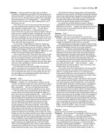
3D audience at CineMec, The Netherlands.
Photo Guy Ackermans
A note from the author:
Since the original publication of this article in Cinema
Technology magazine (March/June 2010 issues), there
have been some further developments which I am
pleased to take the opportunity to update here. In addi-
tion, I have had some very useful feedback from read-
ers seeking clarification on specific points.
The light efficiency table indicates the systems which
require ‘ghost busting’. As mentioned in the article, the
industry was already moving away from providing ghost
busted DCPs towards integrating the process into the
screen server. To the best of my knowledge this has now
been completed and all the relevant screen servers
have been updated. As a result the studios are no
longer distributing pre-ghost busted packages.
In hindsight, the figure of 70% light efficiency for dual
projector operation is rather misleading compared with
the other figures in the table, which quote an absolute
figure from measuring just one channel (left or right
eye). Since only one channel is being measured in the
single projector systems, these measurements are
already subject to a 50% reduction due to the sequen-
tial left eye/right eye switching. Comparing like for like,
the figure in the dual projection column should there-
fore be 35%.
Whilst this would seem to indicate that it is no more
efficient to have two projectors, it should be noted that
systems which are able to display the left and right eye
images simultaneously will benefit from a higher degree
of combinative light. Using yet another audio analogy,
imagine the light channels are like stereo sound chan-
nels going to a pair of earphones. Take one earpiece
away and it’s theoretically half as loud, but in fact it
sounds quieter than that. The effect with light is the
same; if both images are visible simultaneously it gives
the effect of being brighter than if they are sequential.
This is the reason for the 30% efficiency figure for Sony
with RealD, which is a single projector system but deliv-
ers simultaneous left and right eye images.
Finally, a clarification of my reference to triple flash get-
ting more light on screen. By using a larger pixel area,
the latest implementation of triple flash has definitely
been an improvement over previous versions, but what
it still does not do is get more light on screen than a
conventional 2D non-triple flash arrangement. In fact,
the main purpose of triple flash is not really related to
light output, it is designed to reduce the flicker effect
created by the left eye/right eye image switching.
3D Cinema Technologies
there may come a time when the public will ask, “Why is 3D at
the cinema so dull?” Currently, they are still bowled over by the
experience, it’s all new and they have nothing to compare it
with. Give it a couple of years when Sky’s 3D channel is estab-
lished and then ask if our current cinema 3D is good enough.
The bottom line is, I think we need to do better and can do bet-
ter. Let’s keep ahead of the game. Cinema has always tried to
deliver a superior experience over home cinema; that’s where
we are going with 4K. Let’s make sure we don’t leave 3D
behind. If we plan for a bright 3D future today, exhibitors won’t
have to reinvest in upgrading their systems in the future.
It’s not all about light intensity on the screen, is it?
No, far from it. As the title of this article describes, there is more
to 3D than meets the eye! A lot goes on within our brains to fool
us into thinking we really are looking at a 3D image. And here
lies the challenge for engineers in quantifying and measuring
the ‘performance’ of a 3D system. I believe there are parame-
ters we just can’t quantify at the moment and very often the only
way to judge whether one 3D system is better than another is by
subjective measurement through audience survey.
There are proper scientific methods and procedures for this that
should involve a/b switching and blind testing of identical con-
tent in the same auditorium with the same audience. Technicolor
acknowledged the importance of audience surveys in its demon-
stration at ShowEast in October 2009. For Technicolor this was
essential as they would inevitably be questioned over the ability
of a 35mm analogue system to produce the same ‘quality’ as
the inherently stable and precision accuracy of a digital system.
Pity then that they didn’t follow scientific principles for their sub-
jective testing.
Technicolor conducted a two week test with Warner Bros. and
AMC at the Burbank16 with the feature The Final Destination.
The Technicolor 3D system ran in one auditorium while the
same feature was shown concurrently in digital 3D in the same
complex. Movie research firm OTX conducted exit polls for The
Final Destination at both the Technicolor 3D screen and the digi-
tal 3D screen, and reported that the vast majority of both
groups rated their viewing experience as “satisfied” or “extreme-
ly satisfied”. Indeed, Technicolor 3D even generated a higher
“extremely satisfied” response than digital 3D: 28% v. 21%.
But this comes back to my earlier point, what were they compar-
ing it with? How can anyone make a proper analysis without a
reference point? Satisfied, yes, I’m sure it was a great film and
this was the overriding ‘feeling’ of the exit audience. The real
test would have been to have had each group swap over half
way through, or indeed just watch the movie again. Speaking as
a former sound dubbing consultant, a test of a good movie for
me was how many times I could watch it without getting bored! I
found on watching a movie for the second time I would pick up
all the detail I missed during the first screening. I was able to
make a much more valued analysis and appreciation of the
film’s production qualities.
For the benefit of our audiences, we need to be much more crit-
ical of 3D than we are at the moment. I have a feeling this is a
bit like the emperor’s new clothes, no one feels comfortable
speaking out. Competitors don’t criticise the performance of
each other’s systems. Hollywood seems content to be, let’s say,
‘more flexible’ on 3D specifications after doing an absolutely
sterling job with the Digital Cinema Initiative (DCI) for 2D. I sus-
pect no one wants to delay the onset of the ‘cash cow’ that 3D
is turning into. Make hay while the sun shines, especially in
these times of financial crisis. But, if we give a little more atten-
tion to getting 3D ‘right’ now, the 3D sun will shine a lot longer.
So let’s have more competitor ‘shoot outs’, more a/b compar-
isons - and not just between 3D systems. Let’s compare 3D with
2D. Healthy competition is what our industry is all about.
17
18
How does 3D cinema work?
I am sure that most readers will understand the basic principles
of how 3D systems work, but here is a little trick you can play on
your kids, or your financial director when challenged with, “You
want to spend how much on this 3D system?”
•Place your index finger about one foot in front of your face
(not any other finger, otherwise your financial director might get
the wrong idea!).
•Now cover up one eye with your free hand and take a mental
note of what you can see of your finger.
•Move the hand to the other eye and note the difference in the
image.
You will notice that with one eye you can see further around one
side of the finger, and with the other, further around the other
side. Now we normally see these images simultaneously and
our brain ‘mixes’ them into a composite image, which allows us
to see in 3D (or stereoscopic) all the time. Another thing to note;
while you had that finger up in front of your eyes in perfect
focus, did you notice the background? By definition, it was out
of focus. This is another piece of information our brain process-
es to form the stereoscopic view, along with parallax and other
visual cues such as knowledge of the size of specific objects and
estimating their distance away from us. Suffice to say, then, that
there is a high degree of brain processing going on to form that
final stereoscopic image. All 3D cinema systems work on the
same principle of separating the left and right eye images, and
hence all 3D cinematographers work on the same principle of
creating separate images for the left and right eyes.
A 3D system does the same job as your hand in the trick
described above, but it does it so rapidly that the two images
appear to be simultaneous - just like 2D, where film action
appears smooth and realistic even though the images are flash-
ing at us 24 times a second.
In a standard 3D projection system the left image flashes at only
the left eye in one instant, and then the next instant the right eye
receives its image while the left eye should see nothing, or more
specifically ‘black’, just as if your hand was covering the left eye.
Digital 3D systems use a rate of 48 frames per second to
achieve this, so effectively are delivering the left eye/right eye
frames in the same time span as an original 2D 24fps presenta-
tion. In addition to this, digital projectors also apply a technique
called ‘triple flash’ which takes each frame and flashes the
image three times within that same time span. This has the
effect of making a smoother image motion, reducing flicker and
also increases the perceived light on the screen. All 3D systems
need to get more light on the screen since they all suffer from
being rather inefficient. Even the best only lets 30% of the origi-
nal source light through. So, triple flash is good news for the
systems that use a digital projector.
So, why aren’t 3D systems perfect?
In theory, 3D systems have the potential to be perfect and as
good as our own built-in human ‘3D system’. In practice,
though, there are some enormous challenges and problems for
a 3D system to overcome. Let’s go back to our little finger trick
from the previous section. For this second part of the trick you
will need a pair of the darkest sun glasses you can find, prefer-
ably with removable lenses. Now, if a 3D system could block out
the light as your hand did in the first trick, then the 3D system
would be on the route to being perfect. However, these systems
do not stop all the light reaching the right eye from the left eye
image (and vice versa), which leads to an imperfection termed
‘ghosting’.
To demonstrate to yourself an extreme form of ghosting, take
the two lenses from your dark sunglasses and put one over the
other to make a very dark lens. Now, instead of putting your
hand over one eye, put this dark lens combination in front of
the left eye. What your left eye now sees is a ghostly image of
what the right eye is seeing. That’s ghosting, and with 3D sys-
tems it becomes more noticeable with high contrast images - a
black cloak against white snow, for example.
Ghosting is also more noticeable the more the image extends
into the negative Z plane, when the image appears to come
right out of the screen into the auditorium. The three dimensions
of 3D are termed, X, Y and Z. X and Y are the usual two dimen-
sions, Z being the third dimension, depth. Positive Z is going
back into the screen, negative Z is coming out of the screen.
Some 3D systems suffer more from ghosting than others and
some are so extreme that they have to employ image process-
ing known as ‘ghost busting’. The more efficient the system is at
preventing ‘crosstalk’ between the left and right eye images, the
less noticeable the ghosting. Some systems have sufficiently low
crosstalk for the ghosting to be virtually imperceptible even at
the most extreme contrast.
What would make a perfect system?
If you come away from a 3D screening suffering from eye
fatigue or eye strain it could be for a variety of reasons. It is
possible that you have reached a certain age where your eyes
are simply not up to performing 3D gymnastics (me for exam-
ple), or it could be that the film director has just placed too
many demands on your eyes. Let’s go back to the old finger
demo again and take it to extremes.
• Move your finger so close that your eyes begin to cross over
(we Brits call it ‘going boss eyed’).
It’s not particularly pleasant and can even be slightly painful. To
a lesser degree this is what is happening when the director
decides to use a lot of negative Z plane. In other words, the
more and further out into the auditorium the focal plane, the
more work your eyes have to do. It is this constant adjustment
to different focal planes that can strain the eyes. In cutting from
one scene to another, the director also has to take into consider-
ation that the focal planes are consistent. So, the bottom line is,
we could have a perfect delivery of the content but with an
inconsiderate film director - the result is eye strain even for those
with the most gymnastic eyes!
Another factor that can cause eye fatigue, even with a perfect
3D Cinema Technologies
19
delivery system, is the stability and alignment of the captured
image. With CGI animated features this is rarely an issue but
with live action capture, it can be. Companies such as 3ality
have developed high precision camera rigs and the expertise to
use them. Zoom operation and tracking the image with stereo-
scopic capture is quite a challenge, but it can be done very
effectively and with sufficient precision to produce a very high
quality presentation. However, if there is any vertical misalign-
ment between the left and right image it will show up in the
presentation unless corrected in post production. There are
numerous software packages that allow a skilled operator to
correct vertical misalignment, but it’s always much more cost
effective to capture it correctly in the first place. This type of mis-
alignment will generally exhibit itself as an image with slightly
fuzzy edges; you may interpret it as being slightly out of focus.
When it gets to extremes, our brain suspends the 3D belief and
gives up trying to construct it. But all the time it keeps on trying
to construct it and this can also lead to eye fatigue.
There are three basic requirements for achieving perfection in a
3D delivery system:
• Perfect image stability
• 100% left/right eye separation
• 100% light efficiency
So, assuming that we have perfectly structured 3D content to
start with, let’s explore the possible deficiencies in the delivery
systems which can lead to a less than perfect presentation.
Perfect image stability
This is the benefit of digital projection, absolute integrity and sta-
bility of the image is inherent which ensures perfect alignment
between the left and right images. The whole system runs on an
internal clock with precision many millions of times finer than
could ever be achieved with the most lovingly cared for ana-
logue 35mm projector. All those sprockets and wheels, transport
guides, etc, have inevitable mechanical tolerance and the
35mm film media itself is subject to damage and wear as it
passes through the rollers. At a recent BKSTS projectionist train-
ing course, I heard from an acknowledged expert in the field of
projector maintenance (Nigel Shore) that the tiniest build up of
emulsion on a sprocket wheel can result in quite an alarming
shift of the image on screen. To quote Nigel, a 0.25mm shift at
the sprocket wheel translates into 110mm on the screen. So,
whilst analogue 3D projection could claim to achieve stability
within one frame (since left and right eye images are contained
within a single frame), it certainly doesn’t get anywhere close to
digital across a number of frames. It is sometimes appropriate
to hang on to old tradition and old technology, but we rightly
need to be sceptical when claims are made that its performance
in the context of 3D is equal to digital.
D-Cinema is expensive and it does seem unfair that the small
exhibitors who can’t yet afford to upgrade lose out on all this
amazing 3D content. Under ideal conditions, perhaps the per-
formance can get close. But we all know that ‘ideal conditions’
rarely prevail. I believe once we get the measure of measuring
the performance and quality of 3D, it will be obvious for all to
see the difference.
100% left/right eye separation
As described in the opening paragraphs, all 3D systems have
some level of ‘crosstalk’ when delivering left and right eye
images to our respective eyes. The left eye will always see some-
thing of what was intended for the right eye and vice versa. If
this can be kept to a minimum, then it seems our brains filter
the artefact out and we appear not to be aware of it. If the
crosstalk becomes more severe, then of course we become
aware of it and the artefact is termed ghosting. It occurs to me
that this ‘crosstalk’ parameter is something which could be
measured and quantified. Since it clearly has an effect on the
quality of the viewing experience, I would hope that the various
organisations tasked with defining specifications for the cinema
industry will include this parameter in any final system specifica-
tions.
It is important to note that when talking about a ‘system’, this
includes the screen. The quality of the silver screen that is need-
ed to achieve the separation in a polarised 3D system will have
an effect on the measured crosstalk, that is, if the industry ever
gets around to measuring it! I will explain the purpose of the sil-
ver screen later, when we take a closer look at the individual 3D
technologies, but suffice to say at the moment that none of the
systems achieve anything like 100% left/right eye separation.
Some are certainly better than others, but again, without a
proper industry approved system of measurement, we have no
way to define ‘better’. It’s also important to note that the intensi-
ty and contrast of the image are very relevant to this crosstalk
parameter. Take the analogy of a sound-proofed room, or bet-
ter still a multiplex cinema auditorium. The sound proofing has
to be good, but how often have you heard the soundtrack from
the film playing in the auditorium next door? You hear it when it
gets loud, right? The same applies to left/right eye imaging; it
breaks through when it reaches a certain level of intensity, no
matter how good the system may be.
100% light efficiency
Finally, something that is measured and published! Looking at
our comparison table, the Digital 3D Matrix, you can see that
even the most efficient single projector 3D system achieves only
30%. That means that just 30% of the original light source is
getting to the viewers eyes. The other interesting figure in the
comparison table is the Lamp Power Delta 2D v 3D. This rates
the extra percentage lamp power needed to achieve 4.5 ftL. You
can see that, logically, the less efficient the system, the more
lamp power it needs. If only it were as simple as increasing the
lamp power! If that were so, we could just turn up the lamp,
overcome the inefficiency of the system and get a much brighter
image than 4.5ftL. Unfortunately this is not the case.
Let’s take another audio analogy to explain this. In cinema
audio we have a reference level that is maintained from post
production through to play-out in the cinema auditorium. All
projectionists will be familiar with number 7 on the sound
processor level control. Play it at that level and we replicate
exactly the sound mix the director intended. Turn it down and
certain low level ambient sounds begin to disappear, turn it up
and the dynamics and balance of the mix change. It’s the same
with the picture. Turn up the light intensity and not only will the
colours change but also the colour balance. The audience are
then no longer seeing what the director intended.
At the recent launch of the film Avatar in London’s Leicester
Square, the director decided he wanted 6.5 ftL on screen (very
bright by 3D presentation standards). This not only required
double the number of projectors (four in all - but it is a big
screen), it also required a specially produced Digital Cinema
Package (DCP). This was necessary to faithfully reproduce the
original colour and balance. Having one version of a DCP that
can play anywhere on any approved D-Cinema server has been
3D Cinema Technologies
one of the overriding objectives of the DCI’s standards for 2D. I
am sure the DCI aspires to the same objectives for 3D, but at
the moment most distributors accept that multiple versions have
to be produced. These include: ghost busted and non-ghost
busted, subtitled and non-subtitled, plus different packages to
suit the various types of presentation venue.
Competition is the key
The great thing about the 3D cinema market at the moment is
the healthy range of competition. The compatibility and interop-
erability of content files will hopefully continue to ensure this
competition continues. Competition keeps all the manufacturers
on their toes and drives them to further innovation. It also keeps
prices down! None of the systems are perfect but all of the sys-
tems have the capability to deliver a high quality entertainment
experience when each is given optimum operating conditions.
The not so good thing about the market is the apparent dumb-
ing down of so-called ‘recommended standards’ to the worst
performing common denominator. The industry sets a high stan-
dard for 2D with 14 ftL. We all know that cinemas fall short of
this from time to time; lamps are turned down to make them
last a little longer, something that is often overlooked because
12 ftL still looks pretty good, but set an only just acceptable 4.5
ftL standard for 3D and you can be sure that failure to meet this
will be much more commonplace. I have seen enough lacklus-
tre 3D screenings to know that 4.5 ftL is certainly not always
achieved.
So why is 4.5 ftL even considered acceptable? Surely the indus-
try needs to set the bar higher so that a marginal fall in the
lamp output does not result in such a poor performance?
I have heard that the ghosting artefacts in one particular system
become unacceptable above 4.5 ftL and this is the reason
for the current recommended ‘standard ‘. It is a great shame if
this is indeed the case since this is not a VHS/Betamax format
war we are in, or even a Dolby/DTS. Exhibitors are free to
choose whatever system they prefer and will be assured of con-
tent. The studios have the option of raising the bar and setting a
reasonable time frame for all manufacturers to comply. They
should not settle on a specification based on the dominant sys-
tem.
The various 3D Presentation Technologies
All cinema 3D systems work on the same principle of sepa-
rating the left and right eye images. There are three basic
ways to achieve this: circular polarisation, active lens shut-
ters, and colour filtering. All are capable of delivering a very
high quality 3D experience when operating under optimum
conditions. Let’s have a look at how each of these technolo-
gies work
Circular Polarising Systems
Polarising 3D systems have come a long way in recent years.
Did you ever try the polarising sunglasses lens trick, where you
turn one lens 90 degrees to the other and the combination goes
black? Virtually no light gets through. Interesting, but not really
practical for cinema unless you keep your head perfectly verti-
cally aligned for two hours or more! Fortunately the current
systems use circular polarisation filters, which means you can
move your head, relax and enjoy the film.
At the time of writing (September 2010) there are three 3D sys-
tems on the market that use circular polarisation. Two of them,
RealD and MasterImage 3D, are D-Cinema based and the
third, from Technicolor, is designed for 35mm film. All three sys-
tems are very easy to install and can be moved from one pro-
jection booth to another, some more easily than others.
The two D-Cinema systems comprise:
• Projector Polarising Switch Unit
• Silver Screen
• Passive Polarising Glasses
Both systems can be installed on site in front of the lens of a
standard D-Cinema projector. They each have a serial connec-
tor which receives the frame timing data from the projector and
allows the system to synchronise the polarising filters. When the
projector is showing the left eye image the system arranges for
an anti-clockwise polarisation filter to be in front of the lens.
When the right eye image is shown, a clockwise polarisation fil-
ter is presented to the lens.
In the auditorium, the audience puts on their passive disposable
polarised glasses. The left eye lens is an anti-clockwise polariser,
the right eye lens a clockwise polariser. The luminance ineffi-
ciency of both systems originates here. Since the light passes
through two sets of filters, it is attenuated twice. Take the glasses
off when you are watching a 3D film through a polarising sys-
tem and you will see an immediate doubling of the light intensi-
ty. Notice also that when you do this the colours change quite
dramatically. (Remember my earlier comments about colour
balance and light intensity.) If it were possible to remove the
polarising filters at the projector end you would see a further
doubling of light intensity. There is not much to be done about
making polarising lenses more efficient; they are what they are
and by their nature they reduce the light passing through them.
However, RealD has developed a clever box called a light dou-
bler (see Fig.1) which catches the light bouncing off the first filter
and sends it back through the system, thereby improving the
efficiency from around 15% to 30%. This doesn’t necessarily
mean you will get a brighter image from an existing DCP – a
specially prepared DCP is needed to compensate for the addi-
tional brightness – what it actually means is that the system will
use less lamp power for a given ftL on screen. The important
point here is not the efficiency of the systems, but the need for
an absolute luminance standard in 3D. Why was 6.5 ftL used
for the premiere of Avatar at the Empire, Leicester Square rather
20
3D Cinema Technologies
than the more regular 4.5 ftL? Why can’t we all have 6.5ftL? To
answer that question we need to examine the issue of ghosting
and the role of the silver screen in these polarising systems.
Why do polarising systems need a silver screen?
The polarising systems currently on the market have to use a sil-
ver screen. Without it, the ghosting effect would be unaccept-
able. A regular screen has the effect of scattering the light so
that the polarised light incident on the screen becomes de-
polarised. This would result in severe crosstalk between the left
and right eye images.
A silver screen has a surface constructed from millions of tiny
flakes of silver reflectors which reflect the incident light in a
much more defined fashion, thereby maintaining the polarity in
the reflected light. A poor quality silver screen will scatter light
more than a good quality one, making artefacts such as ghost-
ing more noticeable. A good quality screen is an essential part
of a 3D polarisation system and therefore not an area to skimp
on cost. A further point on silver screens is that they may have
variable directional properties and variable light intensity, so you
may experience a variance in 3D image quality depending on
where you are seated in the auditorium.
The main advantage of systems that need a polarising screen is
the savings made by having very low cost disposable glasses.
Polarising glasses usually cost less than a euro, and can be
reused if the exhibitor is willing to invest in a glass cleaning sys-
tem and the labour to operate it. The downside is the cost of the
screen, which is not insignificant, ranging from 5,000 to 10,000
Euros, depending on the size. In addition, a silver screen’s per-
formance with regular 2D content is compromised by the
appearance of a ‘hot spot’. Its ‘virtue’ of not scattering polarised
light leads to an intensifying of light at the point directly in line
with the projector, the centre of the screen. At the low light levels
of 3D (4.5 ftL) this is not noticeable, but with regular 2D content
at 14 ftL it can be. A cinema consultant friend of mine recently
reported a huge variance in ftL measurement across the silver
screen at one site he was testing. With regular 2D, a measure-
ment of 18ftL was found in the centre and 3ftL at the sides!
However, it is probably fair to say that the majority of cinemago-
ers would not notice a ‘hot spot’. It is also an undeniable fact
that the most successful 3D system in the world (by virtue of the
number of installations) uses a silver screen.
Why does one polarising system need ghost
busting and the other not?
You will notice from the performance chart that some systems
have a tick in the ‘Ghost Busted Package’ row, while others do
not. The main difference between the RealD and MasterImage
3D polarising systems is the way in which they implement the
polarising switch at the projector lens. See figs 2 and 3.
RealD uses a liquid crystal electronic switch which configures the
appropriate polarising filter to appear at the correct time.
MasterImage 3D achieves this using a mechanical disc of some
380mm in diameter divided into alternate sections for left
eye/right eye polarisation. MasterImage 3D’s disc spins at
4,320 rpm and in consequence requires a very stable platform,
provided by the sheer weight of the housing, 180lbs (81Kg)!
Fortunately (and rather essentially, I would say) the unit is on
lockable wheels. The spinning disc is synchronised to place the
appropriate filter in the lens path at the appropriate time. The
simplicity of this system results in very few performance limita-
tions, especially in the production of the polarising filters which
can be optimised to a high level of precision.
RealD’s system, on the other hand, is limited by the perform-
ance of liquid crystal technology. Liquid crystal has latency in the
switching response and a limitation in the precision of the polar-
ising filter. It is in the nature of liquid crystal as it transitions from
one polarisation mode to another that it does not entirely switch
off and go absolute ‘black’. A combination of all these factors
results in the system suffering from crosstalk severe enough to
require ‘ghost busting’. The effects of ghosting can be counter-
acted either by the film distributor sending DCPs with pre-ghost
busted content, or by applying ghost busting software to a regu-
lar 3D DCP as it plays out in the projection booth. The advan-
tage of the latter solution is that only one version of the DCP is
required and no account has to be taken of which servers have
ghost busting software and which don’t. However, at least one
Hollywood studio is sending out pre-ghost busted files to all
locations regardless of whether their systems require it or not.
Hopefully other studios will not follow this example. It would be
a shame if systems that perform well enough not to require
ghost busting are then compromised by having to play ghost
busted files, especially since the manufacturer of the system that
requires ghost busting has made its ghost busting software
readily available to D-Cinema server manufacturers.
Sony’s application of RealD
Whilst discussing 3D polarising systems, it is worth noting Sony’s
application of RealD’s technology. It differs quite significantly
and leads to an improved performance in a number of respects.
Sony is well known in the cinema industry for a number of rea-
sons, but over the past five years its campaign to raise the
awareness of 4K cinema has been the most prominent. The
importance of healthy com-
petition in the industry is
highlighted by TI’s recent
launch of its 4K chip. Some
day all D-Cinema projectors
will be equipped with 4K
capability, although it will be
a long time before 4K distri-
bution is the norm. Vast file
sizes and longer duplication
times will prohibit this for a
while yet. In the meantime,
21
Fig.1 RealD XL
Fig. 2 RealD Z Screen
Fig. 3 MasterImage 3D
Fig. 4
RealD
XLS -
Sony
3D Cinema Technologies
though, Sony has chosen to apply its 4K technology to 3D. Not
by giving us a 3D 4K image, but by using the additional pixels
to create simultaneous left eye/right eye 2K images. This of
course leads to improved light efficiency, as shown in the com-
parison table.
Having seen Sony’s 3D system demonstrated on numerous
occasions, my subjective opinion is that the image transition
looks smoother. This could be because the system is not switch-
ing between left eye/right eye like the other systems. Fig.4 shows
how Sony’s projector integrates with the RealD system to deliver
3D into the auditorium. The projector is equipped with a special
double lens for the left and right eye images, and RealD fixed
polarising filters are installed in front of each lens. Standard
RealD glasses are used in the auditorium.
Technicolor’s 35mm analogue solution
3D from a single analogue print is not new, of course. Many of
us will remember a similar system a decade or so ago, well
before we had the benefits of D-Cinema. At first examination,
Technicolor’s system appears to differ in only one respect;
instead of the left and right images being squeezed side-by-side
into one 35mm frame, they are placed above/below each other
in the frame. Like the Sony/RealD system, it uses a special dual
lens with circular polarisers over each and, like all polarising
systems, it needs a silver screen. The polarising glasses are
much the same as those used by RealD and MasterImage 3D,
very lightweight and disposable. Looking further into the
Technicolor system, it has certainly come a long way since those
of a decade ago. Here, analogue 35mm 3D is being refined to
a much higher degree, but will still suffer from the obvious limi-
tations of a mechanical projector. See Fig.5, Technicolor
schematic. Technicolor says it has developed a 3D split lens
based on modern ’ultra’ lens technology (as opposed to the
older cement based lenses) with improvements to eliminate
polariser burnouts, increase the quality of polarisation, and
maximise light transmittance, colour rendering, resolution and
contrast. In addition to the actual lens refinement, Technicolor
also claims to employ algorithms matched to the 3D lens and
prints in order to improve luminance balance between left-eye
and right-eye images, and minimise silver screen effects such as
flattening of the luminance field. The system is claimed to
achieve a 17% light efficiency contingent with proper projection
set-up.
I have now seen three demonstrations of Technicolor 3D: at
ShowEast in October last year, again at the CEA 3D Conference
at the Apollo Cinema, Piccadilly in February this year, and finally
at ShoWest in March. The ShowEast and ShoWest demos were
quite convincing, but I’m afraid the demo at the Apollo just
served to remind everyone in the audience of the limitations of a
35mm print. The main difference between the demonstrations
was that at ShowEast the print was in pristine condition, whilst
the one at the Apollo was obviously well used. The opening
footage had clearly visible scratches, dust and dirt. These imper-
fections are greatly magnified over regular 2D because the left
and right images are in a single frame and to fill the screen the
lens is magnifying effectively twice as much. Any imperfections,
including grain, become much more visible and progressively
deteriorate with use. It is, of course, one of D-Cinema’s greatest
benefits that the first play looks exactly the same as the 1,000th
play. I also noticed some extreme ghosting at the Apollo demo
that I did not see at ShowEast or ShoWest.
I think the jury is out on film-based 3D. It really depends on
whether enough of the major Hollywood studios support it as to
whether it can gain a sufficient installed base to survive. From a
technical standpoint, I am not convinced that a film-based sys-
tem can be in the same performance category as digital, but
then again it is considerably cheaper!
The phenomenal success of 3D over the last year has been
because of D-Cinema. If analogue 35mm 3D really can equal
the performance of digital, then let’s see more proof. I for one
would love Technicolor 3D – and any other film-based solution
– to be the subject of proper scientific subjective testing analysis.
This is why we need properly formulated testing procedures and
standards for 3D. The sooner we get them the better.
The Shutter Glasses System
At the time of writing there is only one active shutter glasses sys-
tem on the market for D-Cinema, from XpanD (formerly known
as NuVision). This system is about the closest you can get to the
finger demo I mentioned early in this article. Just as your hand
shut off the image to the eye you covered, so the XpanD glasses
shut off the image to one eye and then the other in rapid suc-
cession. Like the polarising systems, the switching is synchro-
nised to the frame rate from the projector. The XpanD glasses
simply switch in synchronisation with the corresponding image
on the screen. The big difference is that XpanD does not use
polarised images and consequently the system does not require
a silver screen. Nothing is placed in front of the lens of the pro-
jector so the light efficiency of the system is determined solely by
the glasses. XpanD uses an infrared transmitter installed in the
auditorium to relay the synchronisation signal from the projector.
The glasses are equipped with infrared receivers and a built in
battery which powers the liquid crystal lenses. In their powered
off state the lenses are clear. A signal from the transmitter trig-
gers the glasses to switch on, a voltage is applied to one lens,
then the other, causing them to turn opaque and block the light
accordingly.
Fig. 6 shows the Xpand infra-red transmitter and Fig. 7 the
active shutter glasses.
The system comprises:
• Projector Synchronisation Unit
• Infrared Transmitter
• Active Shutter Glasses
The main benefits of the XpanD system are that it doesn’t need
a silver screen and it doesn’t require any ghost busting. By not
using a silver screen, consistency in quality of the 3D image is
retained regardless of where you are seated in the auditorium. It
is also very simple to install and can be moved easily from one
22
Fig. 6 XpanD emitter
Fig. 7 XpanD glasses
3D Cinema Technologies
Fig. 5 Technicolor 3D
auditorium to another. The downsides are that the glasses are
relatively heavy compared with the disposable polarised type
and the fact that they are not disposable means they need
cleaning between each screening. In addition, the batteries must
be replaced after every 300 hours of use, that’s roughly 150
screenings or 100 Avatars! Cleaning and maintenance are not
the only additional overheads that the exhibitor has to contend
with. Of all the 3D systems, the XpanD glasses are without
doubt the most expensive so, aside from the issues of loss or
damage through rough handling, security needs to be taken
into account when assessing the overall cost of ownership.
Some people think they have the right to own the glasses since
they paid a premium on the ticket, or maybe they just want to
have a souvenir! Some exhibitors have lost as much as 25% of
their inventory over a three month period and so a tagging sys-
tem with detectors at the exits to the auditorium is probably a
worthwhile investment.
Colour Filter Systems
Until very recently, Dolby was alone in offering a 3D system for
D-Cinema based on colour filters. However, Panavision, famous
for high quality 35mm production cameras, and Deluxe,
famous for film processing, have joined forces with Omega
Optical to develop a new system. The Panavision-Deluxe 3D
system will be launched during 2010. If you have a reasonable
understanding of how a colour image is composed for video
transmission, and RGB means something to you, then you
should have no problem getting to grips with how the Dolby
and Panavision systems work. If not, check out this Wikipedia
link for a more detailed expla-
nation first. Suffice to say, our eyes have three primary colour
receptors: red, green and blue. Colour video projection is
achieved by combining or overlaying three frames - one for red,
one for green, and one for blue - to make one full colour
frame. If you imagine that a black and white image uses a
grey scale to achieve the different tones and contrasts in the
image, then you will appreciate that you can have a red image
version of the grey scale, and the same for green and blue.
When these are overlaid, all the range of colours that the eye
can see can be reproduced on the screen. It has been estimated
that humans can distinguish between roughly 10 million differ-
ent colours ref: />Current D-Cinema projection systems are capable of reproduc-
ing more than 16 million colours. It is not a great leap of faith
then to imagine that you could have two ‘reds’ on screen that
are virtually indistinguishable, or two greens or two blues. Take
this a step further and you can see that it would be possible, by
the use of high precision colour filter lenses, to separate these
two almost imperceptible colour differences into two separate
images. This is effectively what the Dolby and Panavision-Deluxe
systems do.
The light coming directly from the projector lamp house is fed
through a precision colour filter wheel fitted inside the projector.
This happens prior to the image being formed in the light
engine. Exactly half the colour wheel has one composite set of
filters to cover RGB and the other half has another, spectrum
shifted, set of composite RGB filters. The wheel spins in synchro-
nisation with the formation of the left and right eye images in
the projector’s light engine. The glasses worn in the auditorium
have precision matched colour filter lenses which then allow the
left and right eyes to see the corresponding filter-matched
images. The crosstalk in the system is very low and therefore
requires no ghost busting.
Figs 8, 9 and 10 show the component parts of the Dolby system
and Fig.11 shows Dolby’s passive filter glasses.
The systems comprise:
• Filter Wheel Assembly
• Filter Control Unit
• Passive precision filter glasses
Panavision-Deluxe is also offering the option of providing the fil-
tering by dual lens application – similar to Sony/RealD and
Technicolor – except that this is not a polarising lens but a
colour filter dual lens. This in turn gives Panavision the ability to
provide their system for 35mm film as well as D-Cinema
(assuming they, like Technicolor, can secure the film stock sup-
ply). There is one further distinct difference between Dolby’s and
Panavision-Deluxe’s applications of the colour filtering method.
The latter applies a technique founded by French physicists
Fabry and Perot back in the 1920s. The technique uses parallel
reflective surfaces tuned to the wavelength of the incident light in
order to block parts of the spectrum and create a comb filter.
The practical outcome is apparently a much simpler and cost
effective lens coating process which is likely to lead to a signifi-
cantly lower price than current reusable non-polarised glasses.
The main benefits of the Dolby and Panavision-Deluxe systems
are that they do not need a silver screen and no ghost busting is
required. As with XpanD, by not needing a silver screen, consis-
tency in quality of the 3D image is retained regardless of where
you are seated in the auditorium. Another advantage with Dolby
and Panavision is that the glasses are passive, very light in
weight and do not require batteries. On the downside, although
the glasses are not as expensive as XpanD’s, the same over-
heads of cleaning and security need to be taken into account.
Over the past year Dolby’s glasses have almost halved in price,
and Panavision-Deluxe’s are expected to be much less again,
but this is still not at a price point where they could be consid-
ered disposable or recyclable. Also, the systems are probably
the least easy to move from one projector to another since the
component colour filter wheel is built in to the projector.
Panavision has the dual lens option, but moving lenses is not
easy, being a two man job. In addition, on the comparison
chart you will notice that Dolby is rated as the least efficient of
all the systems. Clearly, the higher lamp power needed to
achieve 4.5 ftL means that it will need replacing sooner.
Whether this becomes a significant cost factor will of course
depend on how many 3D screenings are scheduled. Efficiency
will certainly become more of an issue if a higher illumination
standard is agreed. I have not seen any efficiency figures from
Panavision but they claim it will be one of the most efficient due
to the lens requiring far fewer layers to achieve the desired filter-
23
Fig. 8 Dolby filter wheel
Fig. 9 Dolby filter controller
DFC 100
Fig. 10 Dolby 3D System
Fig. 11 Dolby glasses
3D Cinema Technologies
ing. Dolby claims that colour filtering achieves sharper images
and retains better colour accuracy than the other systems
because the colour filter is inserted before the light engine. This
could well be the case, and it is certainly my impression from
the numerous demonstrations of Dolby’s system that I have
enjoyed, but this is another area which could benefit from some
scientific subjective testing. It is difficult to put a measurement on
such performance, so it would be great if we could find a way
to quantify it.
As for the Panavision-Deluxe system, I saw this demonstrated in
their screening room in California just before ShoWest and was
extremely impressed.
Conclusions
If you look at the market now, it appears as though the systems
which don’t have disposable glasses (XpanD and Dolby) are
struggling to keep up; the polarised systems are way ahead.
This is not a reflection of cost or performance. All manufacturers
are putting forward perfectly viable business models given the
quantity of 3D films coming through, and they each perform
very well. It just seems that the overhead of managing retain-
able glasses is a prospect that many exhibitors would simply
rather not get into. Many cinemas are already running with the
bare minimum of staff and the idea of adding more duties to
their rota, or indeed adding more staff, is simply not practical.
However, the pressure on the industry to be more ‘green’ will
soon mean that disposing of, or even recycling, the polarised
glasses will be simply unacceptable. Even now, with the small
percentage of 3D screens in the world (less than 10%), the num-
ber of disposable glasses being produced each month is around
10 million! The writing is on the wall, as they say, and the man-
ufacturers are already responding by producing re-usable wash-
able glasses. They are slightly more expensive than the dispos-
able type but still much cheaper than Dolby’s or XpanD’s. Whilst
the overhead of managing the re-use of polarised glasses is
more or less the same as for the other systems, the security fac-
tor need not be as rigorous. Losing one or two pairs every
screening won’t break the bank. That said, the overall cost of
ownership between the systems will narrow significantly once
everyone has to re-use glasses. This is an opportunity for the
non- polarised system vendors to catch up. I for one wish they
would; competition is good.
In closing, as one who has experienced industry screenings that
show all the systems at their very best, I do detect a difference in
the quality of performance. It’s a subjective reasoning and I wish
the industry could find a method of quantifying it. There is defi-
nitely room for improvement in the way we are able to measure
the performance of 3D systems. I appreciate that it takes a long
time for the organisations tasked with creating standards to
arrive at a final publication but, in the meantime, maybe the
industry could benefit from something akin to ‘THX for 3D’.
David Pope
email:
With many thanks to Bill Foster for his editorial
assistance and to the manufacturers who have
provided valuable information.
Thanks to Guy Ackermans for the pictures of a 3D audience at
CineMec in the Netherlands.
24
3D Keeps Moving On
3D Cinema projection is currently a fast-moving and rapidly devel-
oping art. Those who wrote the detailed technical articles in this
guide are experts in the field and fully conscious that some of the
technologies have improved since the pieces were originally written
some months ago. It is in everyone’s interests that a Guide like this
should carry the very latest information possible about how 3D is
developing, and EDCF Manufacturers have made the following
comments, which should be taken into account whilst reading this
guide.
• MasterImage 3D’s standard polarizing filter disk in the MI-
2100 cinema system now achieves a light efficiency of 17% as a
more efficient disk material is used in its construction. Recent
advances by MasterImage 3D have also made available to the MI-
2100 the option to use an “anti reflection” coated filter disk which
raises this light transmission efficiency to 18.5% as well as further
improving polarization efficiency, providing for an excellent presenta-
tion on larger sized screens. The quality and simplicity of the
MasterImage 3D polarizing optical chain provides a clear 3D image
with very natural colours.
• For the largest cinema screens MasterImage 3D recommends the
dual static glass circular polarizers, called MI-1000, which have a
typical light efficiency of 36%.
• Installation of the system can be achieved with the MI-2100 up
and running on screen in under an hour.
• XpanD point out that the Nuvision brand name is no longer
used - the system is XpanD.
• Although the system is often used in order to avoid the disadvan-
tages of the silver screen which is used with polarized systems, the
XpanD system can be used on both silver and matt screens.
• Although XpanD glasses do contain a polarizer, this is not used to
separate left eye from right eye, and “active shutter glasses” is the
most appropriate description for their technology. Image pairs are
repeated during projection several times, generating 144FPS, but the
images are not polarized after leaving the projector, which allows a
normal matt screen to be used, avoiding the negative side effects of
the silver screens needed by other systems. The active shutter glasses
pass the image to one eye whilst simultaneously blocking the image
for the other eye and vice versa. The LCD shutter completely ( near
100%) blocks the image of the inactive eye.
• Active glasses are more costly than passive glasses, but the lifetime
of the glasses is extremely long – up to 5000 shows.
• The installation time for XpanD is now 15 - 30 minutes maximum.
.
• RealD systems no longer need ghostbusted masters - ghost-
busting is now being done in the server during content playback, as
with other 3D systems.
• RealD point out that in all forms of 3D presentation the highest
3D:2D brightness ratio that can be achieved is 50% because all of
the light from the projector, or projectors, is effectively split between
two movies being shown at the same time: the left eye movie and
the right eye movie. The viewer sees only one movie with each eye,
therefore in the best case the luminance is half of what it would be
when a single 2D movie is presented. Even a 100% efficient 3D sys-
tem would offer 50% of the 2D luminance when running in 3D
mode. Absorption in polarizing or color filters causes the brightness
to be lower than that 50% maximum.
• Triple flashing, necessary in all time sequential 3D systems,
requires the projector to insert a dark period between flashes to
allow the viewing system to change from left eye state to right eye
state. In the case of rotating systems, the dark time must be sufficient
to allow the spoke between wheel segments to pass completely
through the light path. RealD has the shortest dark time at 430
microseconds, other systems can be over 1000 microseconds.
• The RealD Cinema System uses a polarizing film to polarize the
light, just as the Masterimage, XpanD and static polarizer systems
do. Systems using liquid crystal polarisers cause the linear polarized
light to become circular and produce just as much dark time as any
other system. All 3D projection systems create some ghosting and all
could benefit from ghostbusting technology.
3D Cinema Technologies
25
Brightness is an important factor in 3D projection systems, as
discussed elsewhere in this document. As a result, “system
efficiency” is an important parameter to consider in choosing
a 3D projection system. The practical factors affecting system
efficiency are different in the different implementations of 3D
projection systems. When considering efficiency, it is important
to understand that the 3D projection system is playing 2
movies at the same time, so the projector’s output is split
between the left eye movie and the right eye movie, providing
in the best theoretical case half the light to each eye.
I will consider each system in turn. Note that the numbers repre-
sented below are “typical” numbers. Individual manufacturers
will vary slightly one way or the other.
1) DLP Based single projector systems. These systems
use a sequential method of 3D which switches the light between
the left and right eyes. This gives full brightness to each eye for
about half the time, which the eye integrates as half brightness.
In practice it takes time to switch between the eyes. The projector
will go black (where it doesn’t project to either eye) for the desig-
nated switching time, further reducing the light to each eye. In
the DLP projectors, this is programmed in as “dark time”. This
switching time varies from about 0. 42 milliseconds to 1.5 mil-
liseconds, depending on the specific system type. This impacts
the overall “duty cycle” of the system. Consider that at 144
frames per second, the total time for a left and a right frame is
1/72 seconds = 13.88 msec. Each eye can potentially be on for
a maximum of 50% of the time, or an “on” time of 6.94 msec. A
dark time of 1 millisecond will result in an “on” time of 6.94-1 =
5.94 msec. The duty cycle is calculated by:
on time/total L-R cycle time.
With 1000 microseconds dark time, the resulting duty cycle is
5.94/13.88 = 42.7%.
a. Shutter glasses. Shutter glasses work as an optical switch at
the eye. They have an input polarizer and an output polarizer,
and a liquid crystal switch in between, which will align or cross
the polarization inside the glasses, resulting in light transmission
or blocking. Typical polarizer efficiency at the input is 42% trans-
mission, and the output polarizer will transmit 84% of light polar-
ized in the same direction. The liquid crystal portion is essentially
transparent. There can be transmission losses of up to 8% if the
optical surfaces are not coated with anti reflection coatings.
b. Z Screen. The Z screen is a polarization switch that resides on
the projector lens. It is made up of a single polarizer and a liquid
crystal switching retarder. The polarizer transmission is essentially
41%, and the liquid crystal cells are essentially transparent. Z
screens are anti reflection coated to eliminate any surface losses.
The polarized light is further transmitted through polarized glass-
es, which are typically 84% transparent.
c. XL Light Doubler. This device “captures” the unwanted polar-
ization that is normally absorbed in the Z screen or other polariz-
ing systems, and converts it into the desired polarization. The
system consists of two beam paths, each having the same effi-
ciency as the Z screen, resulting in a doubling of the light
throughput. The result is a polarization switching filter that is
approximately 82% efficient. This is coupled with eyewear that is
84% transmissive.
d. Rotating Polarizer Wheel. This system uses a rotating polariz-
er wheel at the projector lens. The polarizer is typically 42%
transparent. The polarized light is further transmitted through
polarized glasses, which are typically 84% transmissive.
e. Spectral Division. This system divides the spectrum of the
projection beam into separate left and right spectra. The system
requires that narrow band filters are in place, and that the left
and right filters do not overlap significantly. It is difficult to put
“typical” numbers on the transmission of this system, but suffice it
to say that the efficiency can be less than 50% because of the
light that is blocked to make sure that the filters do not overlap,
but with many bands and careful design this system can become
more efficient
2) Sony System. The Sony single projector system has a
unique approach to presenting 3D. The system dedicates approx-
imately ¼ of its modulator to each eye, on a continuous basis.
This means that about ¼ of the light from the projector is avail-
able to each eye. The system uses polarization. Because the light
is already polarized, the polarization conversion for left and right
eyes is very efficient – between 80 and 90%.
Efficiency calculation
The efficiency can be calculated, if the basic numbers are known.
The calculation is achieved by simply multiplying the duty cycle
by the transmission of each element in the system. Note that for
simplicity, this has not considered the effect of screen gain.
Efficiency calculation examples:
Shutter glasses:
Duty cycle with 1.0 msec = 42.7% Transmission first polarizer 42%
Transmission second polarizer 84% Assume anti reflection coated surfaces
Multiply together – Total transmission = 15.6%
Z screen:
Duty cycle with 0.420 msec = 47% Transmission Z screen 41%
Transmission polarized glasses 84% Total transmission = 16.2%
XL Light Doubler
Duty Cycle with 0.420 msec dark time = 47%
Light Doubler Transmission = 82% Transmission of polarized glasses = 84%
Total transmission = 32.4%
Measured numbers will likely be lower based on practical optical
efficiency of anti reflection coatings and basic glass transmission.
Besides calculating theoretical efficiency, it is also possible to
measure efficiency directly in an operating theatre. Several meth-
ods are used.
1. The first method requires a peak white patch to be projected
onto the screen. With the light meter firmly on a tripod, measure
the screen brightness with the 3D apparatus in place, and again
with the 3D apparatus removed. The resulting efficiency number
does not take into account dark times, which will change the
resulting efficiency by several percent. (Note that the 3D appara-
tus includes glasses and any other part of the system that is
required for 3D projection. Typically the glasses are placed over
the lens of the light meter to ensure that the light meter is emulat-
ing what the eye would actually see.) Calculate the efficiency by
dividing the 3D brightness by the 2D brightness.
2. The second method involves having separate 2D and 3D
peak white test patterns. The lamp current in the projector must
be kept constant for this test. With the projector in 3D mode,
measure the brightness of the 3D test pattern. Switch to the 2D
test pattern and put the projector in 2D mode. Measure the
brightness of the test pattern. Calculate the efficiency by dividing
the 3D brightness by the 2D brightness.
3.The third approach involves comparing the lamp power in 3D
and 2D modes. Set the 3D brightness for 4.5 fL using a 3D test
pattern and measuring through the 3D system including glasses.
Note the lamp power. Reset the projector for 14 fL in 2D mode
(with all 3D apparatus removed from the path). Note the lamp
power. This will give the relative transmissions for each system,
but not absolute transmission numbers, without normalizing for
the difference in light level and considering the efficiency of the
Xenon lamp at different lamp powers. This method will give
exhibitors an idea of the increased power necessary for good 3D.
Method two is preferred for real efficiency numbers.
Note about Screen Gain: Some of the inefficiencies introduced by the 3D
selection methods can be mitigated by introducing higher gain screens.
Higher gain screens reflect more light to the audience (and less to the walls
and ceiling). Using a moderate gain screen will be beneficial in increasing the
image brightness to the audience. Note that screen gain has not been consid-
ered in the comparison of system efficiencies. The Silver screens mandatory
for the polarized systems have not only the brightness advantage mentioned
above as a consequence of the higher reflectance but due to narrower ideal
viewing angles than regular screens can be sensitive to both seat position and
projection port positioning. See Andrew Robinson’s summary in Chapter 6.
Projection Efficiency
Appendix - Understanding 3D
Projection Efficiency
Matt Cowan RealD