reference book on chemical engineering v-i
Bạn đang xem bản rút gọn của tài liệu. Xem và tải ngay bản đầy đủ của tài liệu tại đây (2.69 MB, 363 trang )
•
emlca
• •
=n Ineelln
D.Sen
(f.U
NEW
AGE
INTERNATIONAL
PUBLISHERS
Reference
Book
on
Chemical
Engineering
THIS PAGE IS
BLANK
Reference
Book
on
Che
ical
Engineering
Volume
I
D
.Sea
8.Ch.E.
Fellow
of
Ill", Institution
of
Engineers (India)
Former Listed 10
81
Consultant
,
Retired Chief Engineer (Chern.)of
BVFCl
, (Formerly
HFCl
)
Namrup
Unit,
Assam
NEW
AGE
INTERNATIONAL
(P)
UMITED, PUBUSHERS
Now
Delli, . B'"&,I",,, .
Ch.
n
n,;
• Cochin • G h
i • lIyd<n.b. d
J
.undh.
, • Kolkau •
Luckll_
. Mumb.; •
Ranch;
Copyright © 2005 New Age International (P) Ltd., Publishers
Published by New Age International (P) Ltd., Publishers
All rights reserved.
No part of this ebook may be reproduced in any form, by photostat, microfilm,
xerography, or any other means, or incorporated into any information retrieval
system, electronic or mechanical, without the written permission of the publisher.
All inquiries should be emailed to
ISBN (10) : 81-224-2331-0
ISBN (13) : 978-81-224-2331-0
PUBLISHING FOR ONE WORLD
NEW AGE INTERNATIONAL (P) LIMITED, PUBLISHERS
4835/24, Ansari Road, Daryaganj, New Delhi - 110002
Visit us at www.newagepublishers.com
'To
My
Mother
'Wlio
lias takJn mucli interest
in
progress
of
the
flooK-,
the
flooK-is
adicatea
THIS PAGE IS
BLANK
PREFACE
A Chemical
Engineer
needs
to
know
not
only
the
im~ide
cha
nge
s in a Production
Process viz. Chemical, Physical,
Therm
ochemical,
Thermodynamics
and
Kinetics,
but
also he
has
to
know
the
basics
of
other
engineering
disciplines
as
well
as
current
developments.
During
my
long service
period
in
Production
,
Process
Design
an
d Projects,
I found
most
of
these
information
are
available
at
different
sou
rce
s
and
is
not
always
possible
to
acquire
the
se
infonnati
on
always
. 'Ib
meet
these
gaps, I
have
given
as
much
information
as
possible
in
Volume I
and
Volume II of
this
book on various processes,
data
tables, so
me
unit
operations
etc.
usuany
required
by
Professional Chemical
Engineers
and
Chemi
ca
l Engg.
students.
In
addition, a
chapter
on Gl
ossary
of
Terms
has
a]so
been
provided for
refreshing
the
essentia
l information un
chemistry
and
other
topics.
In
pr
e
paration
of
this
"Reference
Book
on
Chemical
Engineering"
so
me
senior
e
ngineer
s
working
in
chemical
industries
have
extended
support
in
preparation
of
some
chap~n;
;
ip
parlicular
1 like
to
thank
K.
OM
Ex.
ED
, KRIBHCO,
Hazirll
; D.K
Roy,
Ex.
GM,
Namrup
Fertili
se
r
Unit;
KP.
Sinha,
~r.
Developme
nt
Engineer,
DCL,
Pr
ofessor
U.P.
Ganguly
,
Retired
, Chern. Engg.
Deptt.
,
Lr
~
T
.
Kharagpur
had
reviewed
this
book.
The
index for words
had
been
provided.
Th
e
author
also
likes
to
t
hank
Ms
. B.
Sen
for
sec
ret
a
rial
ass
is
tance
in
pr
e
paration
of
the
manuscript
Kolkata D.SEN
THIS PAGE IS
BLANK
CONTENTS
Preface (uii)
1.
Fertilisers
1
2.
Heat
Transfer
25
3. Pulp and Paper
37
4.
ehlor
Alkali Industry
45
5.
Cellulosic Fibres (Rayon)
50
6.
Selected Process Equipment Design
63
7. Petroleum Refinery
70
8. Active Carbon
75
9.
Refrigeration
78
10.
Coal
Tar
Chemicals
96
11. Refractory Bric
ks
103
12.
Explosives and Detonators
107
13. Water Treatment
111
14. Metal Cleaning Process
128
15.
Mangane!!le
Di
oxide
130
16. Wind 'furbine for Power Generation
133
17.
Centrifugal
Pumps
13S
18. Industrial and
Town
Gases
143
19.
LNG Production
159
20
.
Products M
an
ufactured from Benzene, Ethyl Ben2ene,
Ethylene. Ethylene Oxide, Ethanol and Others
162
21.
Synthetic Iron Oxide Pigment
167
22
.
Dyes
, Intermed
iates
and Dyeing
170
23. FlourC
l;
cent
or Optical Whitening Agent
(FWA
)
172
24A.
Flame
Retardants, Halans, Fire AlarmsIHydrants
and Rubber and Expanded
Pla
stics
174
24B.
Float Gl
as
s, Carbon Black, Electrophoresis, Dry Ice
and Technological Development in Iron and
Steel
Industry
and Electrolytic Chlorinator
179
25. Ceramic Colouring Materials
185
(x)
26. Glass
Fi
br
es
for
Insulation and
Ot
her Uses 187
27.
Plastics
190
28.
Flocculation
195
29.
Phosphoric Acid
198
30. Electropl
ating
Process
207
3J.
Couling Towers
212
32.
Paints and Painti
ng
217
33.
Biogas
Pl
ant (Domestic Use)
223
34. Sugars
225
35.
Phenols for D
is
infection
230
36
.
Ferrous Alloys
232
37.
High Car
bo
n Charge Chrome
234
38.
Characte
ri
stics
of
Va
lves Used in Chemical Process Industry
236
39
.
Boiler Feed Pumps and Standard Values
fo
r Boiler Feed
and Circul
at
ing Water
237
40. Crystallizer Cl
assi
fication
240
4J. Brief on Offshore Oil Exploration and
Tr
ansportation Pipeli
ne
242
42.
Insecticide or
Pes
ti
ci
de
243
43.
Critical Pa
th
Me
thod W
PM
)
254
44
. Psychrometry
255
45. Glasses and Textile Glass Fibr
es
258
46. Environment and Pollution Air and Water
260
47.
Vegetable O
il
Refining
275
48
.
Furfural
282
49.
Pol
ye
th
yl
ene
Terep
htha
l
ate
Resin (Bottle Grade)
285
50. Process Eva
lu
ation
of
a Ch
em
ical Plant 288
51.
Detail Project
Cost Estimation 298
52.
Types
of
Co
ntract
307
53.
Pr
oj
ect
Financi
al
Management
309
54.
I
SO.90oo
Series Quality
Assu
rance
Syste
m
320
55.
Conver
sion
Factors
328
Index 336
1. GENERAL INORGANIC FERTILISERS
These are plant nutrients which are grouped as nitrogenous, Phosphatic and mixed fertilisers
with or without potassium chloride (muriate of potash, MOP). Among nitrogenous fertilisers, urea
containing 46–46.5% (wt) nitrogen is most important because of high nutrient content and is widely
produced and used. Di-ammonium Phosphate (DAP) single super phosphate (SSP), mono ammonium
phosphate (MAP) and dicalcium phosphate (DCP) are common phosphatic fertilisers. CAN is
Ammonium nitrate mixed with lime. Mixed fertilisers are balanced nutrients for plants as they contain
nitrogen, phosphorous and potash in various proportions. Fertilisers are generally termed as containing
N : P
2
O
5
: K
2
O or simple N : P : K where N stand for % nitrogen, phosphate as % P
2
O
5
or simple
P and Potassic as % K
2
O or simple K. The ratio is % by wt.
Types of Inorganic Fertilisers
Type Constituents, % by wt Remarks
Nitrogenous Fertilisers use as prills and industrial
Urea, NH
2
CONH
2
N = 46–46.5% Use as crystals or Prills
Ammonium Nitrate, N = 34.5% Explosives and fertiliser use
NH
4
NO
3
UAN soln. N = 20% or NH
3
= 23% UAN is urea mixed with ammonium
nitrate
Nitrolime or CAN N = 25% Mix. of 60% amm. nitrate and 40%
lime stone (CaCO
3
)
Ammonium Sulphate, N = 21% Fertiliser use
(NH
4
)
2
SO
4
Phosphatic and Potassic:
Monoammonium Phosphate N = 11%, P
2
O
5
= 52% Fertiliser use
MAP (NH
4
H
2
PO
4
H
2
O)
Diammonium N = 18%, P
2
O
5
= 46% Fertiliser use
Phosphate, DAP or 21% = N, 53.5% = P
2
O
5
(NH
4
)
2
HPO
4
H
2
O
1
1
Chapter
FERTILISERS
2 REFERENCE BOOK ON CHEMICAL ENGINEERING
Dicalcium Phosphate, P
2
O
5
= 51% Fertiliser use
(CaHPO)
4
Single Super Phosphate P
2
O
5
= 16–18% Fertiliser use
(Mixture of mono calcium
phosphate and Gypsum)
Tripple Super Phosphate P
2
O
5
= 46–48%
TSP (mix of tricalcium
phosphate and Gypsum)
Liquid spray fertilizer (i) 24% AqNH
3
soln. Fertiliser use
Developed after (ii) Ammonia nitrate or urea
(1950 in USA) aq. soln with liquid NH
3
upto 50%
(iii) Non press. Appln 32%
aq. soln of urea and ammon.
nitrate
Mixed Fertilisers
N P K 15 : 15 : 15 Fertiliser use
12 : 12 : 12
8 : 8 : 8
N P 18 : 46
16 : 20
20 : 20
N P K (other type) 17 : 17 : 17 Fertiliser use
10 : 22 : 26
14 : 28 : 14
19 : 19 : 19
N P K (foliar grades) 12 : 4 : 6 Foliar spray
6 : 12 : 6
5 : 8 : 10
Controlled release urea aldehyde Slow release to soil
fertiliser
2. BY DANGER CRITERIA, THERE ARE FOUR TYPES OF FERTILISER
A type explosive fertilisers, exm. Ammonium nitrate-storage conditions are stringent.
B type fertilisers are self-sustaining progressive thermal decomposition.
C and D type fertilisers are not self-sustaining as well as do not subject to progressive thermal
decomposition.
Group B fertilizers are more important for storage.
FERTILISERS 3
3. RAW MATERIALS FOR FERTILIZERS PRODUCTION
Nitrogenous Fertilisers
For manufacture of nitrogenous fertilizers, ammonia as intermediate product, is manufactured
first.
Raw Materials
Natural gas (N.G) containing mainly methane and other higher hydrocarbon stock. (LSHS) is
also used where natural gas is not available. Other oil refinery distillation product like Naptha is also
used as starting raw material although it is costlier. Even low sulphur and low ash bituminous coal
is used in some plant (South Africa) as raw material.
Process Steps
(i) These involve production of raw gas (CO + H
2
) with pre or post desulphurisation depending
on type of raw material used. For N.G, pre-disulphurisation is carried out first followed by steam-
air reforming (two stage) using compressed air and compressed natural gas. H.P. steam generation
from reformed gas (R.G.), H.T. CO conversion and L.T CO conversion for generation of equivalent
H
2
from CO, CO
2
gases in the raw gas are absorbed in a CO
2
absorber using pot. Carbonate with
anticorrosion chemicals viz V
2
O
5
or As
2
O
3
or using MEA/DEA absorption for CO
2
followed by
methanation to convert residual CO and CO
2
to methane. CO
2
from CO
2
absorbing solution is
recovered in a desorption tower using heat for regeneration of CO
2
. The byproduct CO
2
from CO
2
desorption tower, containing over 96% CO
2
, is sent to urea plant for production of urea. The
synthesis gas obtained after methanation and having H
2
and N
2
in 3 : 1 molor ratio, is used for
ammonia synthesis and compressed to 200–250 Kg/Cm
2
g and synthesized to produce ammonia in
the H.P ammonia reactor with recycle in the synthesis loop having synthesis gas compressor with
recycle gas circulator, primary and secondary condensation using cooling water and ammonia
refrigeration respectively. The ammonia produced as liquid is about 99% (wt) and stored in horton
sphere for sending to urea plant for urea production. The conversion of H
2
to NH
3
in synthesis loop
is about 14–16% (Vol) and inert gases from synthesis loop is sent to ammonia recovery section. Only
make up synthesis gas (H
2
+ N
2
) is fed to the NH
3
reactor using KM
1
and KM
2
catalyst, to the extent
ammonia is produced due to catalytic conversion of H
2
and N
2
into NH
3
.
3H
2
+ N
2
= 2NH
3
∆H = –22400 Btu/1b mole
The overall energy required per ton of ammonia various from 5–10 Geiga calories/ton depending
on patented process of Haldor Topsoe, Texaco, Kellog, etc.
(ii) In case of LSHS, desulphurisation by cold methanol is carried out after raw gas generation
in gasifier using oxygen from air separation unit and O
2
compressed to 28 Kg/sq.cm. In the gasifier
partial oxidation reaction takes place in the flame with generation of raw gas (H
2
+ CO).
When refinery naphtha (boiling range 170°C) is used as raw material, two stage desulphurisation
is carried out first prior to gasification in a reactor. The rest of the process like CO conversion, CO
2
absorption using hot Pot. Carbonate soln. with V
2
O
5
/As
2
O
3
as corrosion inhibitor, (As
2
O
3
) is normally
not used now due to pollution) and methanation followed by high pressure ammonia synthesis. By
product carbon pellets is obtained when LSHS is used for gasification.
Fuel used in reforming section is same as starting raw material viz N.G. or naptha (Vaporised).
Texaco, USA is the licensor for gasification section. Other process licensors are ICI, KELLOG etc.
4 REFERENCE BOOK ON CHEMICAL ENGINEERING
4. DETAIL PROCESS DESCRIPTION FOR AMMONIA PRODUCTION USING N.G.
AS FEED STOCK
Natural gas is compressed to 41 ata and preheated to 400°C in N.G. fired heaters and sent for
desulphurisation using comox catalyst (Cobalt – moly and Zinc oxide) catalyst. The type of catalyst
required depends on inlet sulphur concentration as H
2
S and organic sulphur. The gas is then mixed
with H.P. steam at 40 ata and 370°C. The mixed N.G. is then (further) heated in mixed gas heater
upto 500°C and fed to primary reformer at 32 Kg/Cm
2
g containing primary reformer catalyst in
nickel tubes of HK-40 material. For 600 MT per day ammonia plant 240 nos. tubes of 6" diameter
in vertical row are required. The primary reformer furnace is generally having side fired N.G. burners
where N. G. is burnt as fuel (top and side fired burners are also used in primary reformer). The
reformer furnace temp. is kept at 1000°C and steam carbon ratio is maintained in the primary
reformer tubes between 3–4. The tubes expand upwards and gas flows from top to bottom. Primary
reformation of N.G. takes place inside the tubes at 700–800°C in presence of nickel based catalyst.
The tube life is around 100,000 hours.
The exit gases from P.R. at 30 Kg/sq.cm and 795°C is further reformed in secondary reformer
at 950°C. In the secondary reformer in the presence of catalyst, further reformation takes place at
31 ata when some H
2
burns to produce heat necessary to convert most remaining feed stock to H
2
,
CO and CO
2
. Air is fed to S.R so as to provide necessary N
2
in synthesis gas in the molar ratio
of 1:3 (N
2
: H
2
). The exit heat from S.R gases is recovered in super heaters, N.G. heaters and air
heater and mix gas heater in the reformation section. The hot S.R exit gas, containing 12% CO at
1000°C, is then sent to R.G boiler to generate H.P. steam followed by two stage catalytic CO
conversion when equivalent H
2
is produced from CO in raw synthesis gas, (H
2
+ CO).
CO + H
2
O CO
2
+ H
2
General Reaction in Primary Reformer
C
n
H
2n+2
+nH
2
O→nCo + (2n + 1)H
2
General reaction
CH
4
+H
2
O→CO + 3H
2
1
CH
4
+2H
2
O→CO
2
+4H
2
2
C
2
H
6
+4H
2
O→2CO
2
+7H
2
3
C
3
H
8
+6H
2
O→3CO
2
+ 10H
2
4
C
4
H
10
+8H
2
O→4CO
2
+ 13H
2
5
C
5
H
12
+ 10H
2
O → 5CO
2
+ 16H
2
6
C
2
H
6
+2H
2
O→2CO + 5H
2
7
C
3
H
8
+2H
2
O→2CO + 7H
2
8
C
4
H
8
+2H
2
O→4CO + 8H
2
9
C
5
H
10
+5H
2
O→5CO + 10H
2
10
Reactions 1 to 6 are major reactions. Other reactions possible in varying conditions of pressure
and temp. in the primary reformer are:
COS + H
2
O → CO
2
+H
2
S
2CO → C+CO
2
C+H
2
O →CO + H
2
FERTILISERS 5
CO
2
+C → 2CO
CH
4
+CO
2
→ 2CO + 2H
2
2CH
4
→ C
2
H
6
+H
2
H.T. CO conversion is carried out at 327°C/427°C when CO at exit is around 2–3% and LT
CO conversion at 210°C/330°C. The CO and CO
2
content of L.T. converter is 0.30% and 18.5%
respectively. The heat in exit gases from H.T. converter is used to preheat boiler feed water heaters
and L.T. converter outlet is used to produce, L.P. steam. The L.T. exit gas is then sent to decarbonation
tower to remove CO
2
with either Vetrocoke soln. or Benfield soln. (Pot. Carbonate with V
2
O
5
). Both
the CO
2
removal processes are proprietory items. Now a days Vetrocoke soln. (hot potash with
As
2
O
3
) in not used due to pollution problems. Corrosion in-hibitors As
2
O
3
/V
2
O
5
forms a stable
passive oxide film in towers which prevents corrosion; absorption of CO
2
by Pot. Carbonate soln.
takes place as per the following reaction :
K
2
CO
3
+ H
2
O + CO
2
→
2KHCO
3
Regeneration of the bicarbonate is done by heating of the soln. in the desorption tower with
reboiler :
2KHCO
3
→
K
2
CO
3
+ CO
2
+ H
2
O
Heat supply to reboiler is by steam. The generated CO
2
gas from desorption tower/regenerator
top is cooled in a cooler to remove condensate and sent to urea plant.
The decarbonated gas at 60°C and 26 ata pressure is preheated by hot methanator outlet gas
and partial H.T. CO converter gas upto 315°C and feed to methanator where remaining CO and CO
2
are converter catalytically by iron oxide catalyst to methane.
2CO + 5H
2
O
→
2CH
3
+ 2H
2
O
The heat recovery as well as operating parameters in reformation section to methanator varies
according to process licensor scheme. Methanator is often deleted and in its place liquid N
2
wash
is carried out in process licensor e.g., C.F. Brown Process.
The hot gas from methanator after heat exchange, cooling and condensate separation is the
synthesis gas having H
2
, N
2
ratio within 3 (molar) and CO + CO
2
within 5ppm, CH
4
= 0.75%. The
synthesis gas is sent to compressor at 45°C and 25 ata pressure for compression to 200–250 Kg/
sq. cm. The total pressure drop to primary reformer to methanator is designed at 5–6 Kg/cm
2
.
In the synthesis loop, make up pure synthesis gas mixture along with recirculated synthesis gas
is compressed and cooled in cold exchanger (Tube side) and in the ammonia cooled condenser and
ammonia separated in secondary cold ammonia separator. The gas then enters shell side of cold
exchanger and then shell side of hot exchanger and then to ammonia converter packed with KM
1
(often KM
2
also) iron catalyst where NH
3
is formed at a temp. of 425°C–500°C. Reactor temp. is
controlled by by-pass gas valve in each of 3 catalyst beds.
H.P. steam is generated in boiler coil inside the NH
3
reactor. The converted exit gas is then
cooled in primary water cooled condenser from 70°C to 38°C and then to sec. ammonia cooled
condenser. The liquid ammonia condensed is separated in primary separator, sec. separator and
unconverted gas is recycled to the recirculator and a small part is purged to ammonia recovery sec.
from recycled gas to keep inerts, Argon, CH
3
within limit. Liquid ammonia from primary and two
secondary separators is put in let down tank from where it is taken to Horton sphere for storage.
6 REFERENCE BOOK ON CHEMICAL ENGINEERING
H.P.
Auxiliary
boiler
To Plant
network
Primar
y
reformation
M .P. S ervice
boiler
Steam network
Air secondar
y
reformation
H.T. CO conversion
L.P. boiler for steam
g
eneration
L.T.CO-conversion
CO absor
p
tion
2
CO desor
p
tion
2
Methanation
Ammonia s
y
nthesis
and refri
g
eration sec.
Ammonia stora
g
e
Li
g
ammonia to
consumin
g
p
lants
CO to urea
2
Fig. 1. N.G. steam reformation (HTAS) for ammonia synthesis in (HTAS) process.
The flow scheme of gases in the synthesis section also varies as per process licensor’s design
depending on the extent of waste heat recovery from syn. converter. Often two syn. converters are
required for greater conversion to ammonia as in C.F. Braun’s Process as well as some design of
Uhde. CO
2
absorption also varies – pressure swing absorption (ICI) and regeneration by flashing and
physical absorption using selexol/sepesol and MDEA Process (BSAF) and more common Process of
CO
2
removal by DEA and MEA depending on process adopted by process licensor.
FERTILISERS 7
5. SYN. GAS (CO + H
2
) GENERATION BY NONCATALYTIC FUEL
OIL/LSHS GASIFICATION
There are two process licensors Texaco and Shell for production of raw syn. gas by non-
catalytic gasification of Fuel Oil/LSHS using oxygen by the partial oxidation route. Texaco had,
however, developed a gasification process using these feeds stocks with enriched air (with oxygen).
General Formula
C
m
H
n
S
r
+ mO
2
→
m/2 CO + (n/2 – r) H
2
+ rH
2
S.
Side Reaction
C
m
H
n
S
r
+(r – n/2 + 2) H
2
→
CH
4
+ (m – 1) C + rH
2
S.
H
2
O+C
→
H
2
+CO
H
2
O+CH
4
→
3H
2
+CO
H
2
O+CO
→
H
2
+CO
2
Partial Oxidation of Heavy Fuel Oil (feed stock)
C
15
H
24
S
2
+ 15/2 O
2
→
15CO + (24/2 – 2) H
2
+2H
2
S
or C
15
H
24
S
2
+ 7.5 O
2
→
15CO + 10H
2
+2H
2
S
In Case of Full Oxidation
C
15
H
24
S
2
+ 20O
2
→
15CO
2
+ 10H
2
O+2H
2
S
Side Reactions
C
15
H
24
S
2
+ (2 – 24/2 + 2) H
2
→
CH
4
+ (15 – 1) C + 2H
2
S
or C
15
H
24
S
2
+ 8 H
2
→
CH
4
+ 14C + 2H
2
S
H
2
O+C
→
H
2
+CO
CH
4
+H
2
O
→
3H
2
+CO
CO + H
2
O
→
H
2
+CO
2
Process
Oxygen gas from Air Separation Plant is compressed to 52 Ata, mixed with H.P. steam and
the mixed gas is led into partial oxidation gun along with preheated heavy fuel oil inside the gasification
reactor where flame reaction takes place producing raw syn. gas (H
2
+ CO). The nitrogen in fuel
oil is converted to molecular N
2
and sulphur to H
2
S and small amount of COS. The gases are then
quenched with water to remove unreacted fuel oil. The carbon water from quench vessel in then
sent to carbon recovery section where carbon is separated and pelletised for use in service boiler
and water slurry recirculated with the make up water to quench vessel. The H
2
S in raw syn. gas
at 51 ata and 48°C is then sent to rectisol section for desulphurisation with cold methanol at –20°C.
Due to presence of considerable sulphur compound (H
2
S, COS) etc. cold methanol is used in this
process (Rectisol) using ammonia refrigeration. Sulphur is reduced to 0.1 ppm.
The gases are then led into HT CO conversion after heating where shift reaction takes place
at 327/420°C and most of CO is converted to H
2
.
CO + H
2
O
→
CO
2
+ H
2
The exist gases from HT CO converter contain 0.3% CO and CO
2
gases are absorbed with
cold methanol at (–50°C) in Rectisol section where most of CO
2
is physically absorbed in cold
8 REFERENCE BOOK ON CHEMICAL ENGINEERING
methanol which is then regenerated by heat and flashing. The generated CO
2
, about 96%, is sent to
Urea Plant and other consuming plant. The regenerated methanol soln. is sent to CO
2
absorber. The
exit gases from absorber still contain some CO and CO
2
along with Methane and Argon. The gases
are then first adsorbed in molecular sieve vessel where CO
2
is adsorbed (below 10 ppm) and methane
below 50 ppm. The purified gases are then sent to liquid Nitrogen wash tower where CO, CH
4
and
Argon are removed and after regeneration of liquid Nitrogen containing CO, CH
4
are Flashed out and
stored for use as a fuel. The purified mixture of Hydrogen gas and Nitrogen, in the ratio of 3 : 1,
is then compressed to 200 – 250 Kg/cm
2
along with recycle gas containing unreacted Hydrogen,
Nitrogen and some Ammonia is sent to syn. reactor where after preheating enters the catalysts beds
in ammonia converter where ammonia is produced at 500°C.
3H
2
+ N
2
= 2NH
3
∆H = –22400 BTU/1b mole
H.P. Steam is produced in the syn. reactor, flashed in syn. boiler and used in the process.
Service
boiler
Steam
network
Carbon
p
ellets
Desul
p
hurisation
b
y
cold methanol
H.T. CO conversion
Li
q
. N
2
wash
LSHS
(
Stora
g
e
)
Shell
g
asification
CO absor
p
tion
b
y
rectisol
p
rocess
2
CO
2
desorption
Ammonia s
y
nthesis
and refri
g
eration sec.
Li
g
. ammonia stora
g
e
Li
g
. ammonia to
consumin
g
p
lants
Air se
p
aration
Tail
g
as
Liq.
N
2
Air
CO to urea
2
O
2
Fig. 2. Shell gasification (partial oxdn.) ammonia synthesis process.
FERTILISERS 9
Table 1
CO
2
Removal Process
Plant Supplier Uhde activated MDEA of Uhde low heat hot potash
BASF U O P
H.P. Boiler FW preheating 31.2% 29.2%
L.P. steam generation 14.9% –
Heat for CO
2
removal 31.4% 49.9%
Demineralised → water 22.5% 20.9%
preheating
Total heat available 100%
Table 2
CO
2
Removal Process
Process MDEA (BASF) Low heat hot
potash (UOP)
Absorber outlet CO
2
100 ppm 1000 ppm
Kcal/NM
3
368 777
CO
2
recovered in 96.51 99.52
regenerator, %
CO
2
purity (dry), % 99.75 99.06
Table 3
UHDE Ammonia Synthesis Loop Data
H
2
/N
2
ratio 2.95
No. of syn. reactor One
Mu. syn. gas 27 bar, 6°C
Ammonia separation temperature –10°C
125 bar steam generation t/t NH
3
1.17
Waste heat used in H.P. steam 60%
raising%
Waste heat removal in cooling water 14.81%
Chiller duty 25.01%
Total heat available 100%
10 REFERENCE BOOK ON CHEMICAL ENGINEERING
Table 4
Energy Consumption for Ammonia Plant (N.G. based)
Process Reformation and syn. –HTAS, HTAS
CO
2
shift (Two stage PDIL) and
Methanator (PDIL)
Plant capacity 600 MT/day 1000 MT/day
Location India Europe
N.G. (feed stock Fuel
*
) 8.49 7.641 Gcal/Te
G.cal/Te
N.G. Methane content 78–91% (Vol) Over 90% (Vol)
N.G. per ton ammonia 1218 SM
3
N.A.
Electrical Power (excl. CT) 61.20 KWH/Te 28.6 KWH/Te
Polished water 4.302 M
3
/Te 4.31 M
3
/Te
CO
2
Production rate 1.132 Te/Te N.A.
Cooling water 643 M
3
/Te 210 M
3
(sea water)/Te
M.U. water for C.T. 13.8 M
3
/Te N.A.
CO
2
removal process Benfield N.A.
Energy per ton ammonia, 10.875 7.02
G.cal/Te
*
Correspond to full enthalpy of steam and water at 0°C.
6. DEVELOPMENT IN AMMONIA PRODUCTION
(1) Raw Syn Gas Generation
Most of the fertilizer plants in the world use steam methane reforming process followed by
partial oxidation of heavy fuel oil (LSHS) as feed stock. One smaller plant uses coal gasification to
produce raw gas. MW Kellog of U.S.A. had developed reforming exchanger system for raw syn.
gas generation. The reforming exchanger contains open tube catalyst tubes hanging from exchanger
top. Oxygen mixed with air, steam and NG feed (2/3rd) are 1st fed to catalytic adiabatic reformer
where certain amount of reforming takes place at a temp. of 954–1010°C. Nearly 1/3rd of balance
process feed NG and steam enter the reforming exchanger from top while adiabatic reformer effluent
also enters the shell side of reforming exchanger providing recovery of heat for reforming reaction.
The outlet gases from reforming exchanger goes to feed/effluent H.E. where mixed gases are
preheated and reformed gases then follow the heat recovery system of CO shift converters, CO
2
removal and methanation and compressed prior to entering ammonia synthesis loop.
Table 5
Process Data for Reforming Exchanger (Kellog)
O
2
in enriched air Upto 30%
Mixed feed pre heat temp. 480° – 620°C
Overall, steam/carbon ratio 3.3 – 3.8
Adiabatic reformer exit temp. 925° – 1040°C
Design methane slip 0.5 – 0.7% (vol) dry
FERTILISERS 11
However, the reforming exchanger system, where no secondary reformer is used, changes the
conventional heat balance system of the process. Most of the high temp. heat, via the heat exchanger
reformer is returned to the process and will thus not be available for H.P. steam production and
excess of low temp. heat will be available for med. or L.P. steam production which can not be utilized
in ammonia plant and H.P. steam must be generated in auxiliary boiler or service boiler for use in
H.P. steam turbine drive of syn. gas compressor. The overall energy efficiency will entirely depend
upon the efficiency of auxiliary steam generation.
(2) CO
2
Removal Process
There are several proprietory processes viz Vetrokoke hot potash system using arsenic oxide,
Benfield process using V
2
O
5
, Catacarb process, MDEA process of BSAF, Hot Potash process of
UOP, low temp. (–50°C) Rectisol process. In addition, MEA and DEA of CO
2
process is also used.
In all these processes, absorbed CO
2
rich soln. from packed absorber is regenerated by heating and
flashing to low pressure (0.15 Bar). The efficiency depends on heat economy for regeneration of
soln. as well as power recovery by soln. turbine in the absorber outlet soln. to recover part of power
reqd. for pumping the regenerated soln. to absorber. About 40% recovery is possible. Heat required
for regeneration of soln. varies from 370–800 Kcal/NM
3
CO
2
. CO
2
conc. from 96–99% (vol) is
recovered CO
2
.
(3) CO Shift Conversion
Generally two stage (HT and LT) shift reactor is used with L.P. steam (3.5 ata) generation at
outlet of HT converter. The temp. at HT converter is maintained at 330°–425°C and that of L.T.
converter, 210°–330°C.
Shift reaction : CO + H
2
O
→
CO
2
+ H
2
(4) Methanation
The remaining CO (0.3%) and CO
2
in raw syn. gas after CO
2
removal is removed in catalytic
methanator working at 315°/220°C.
Methanation reaction: 2CO + 5H
2
→
2CH
3
+ 2H
2
O
CO
2
+ 3½H
2
→
CH
3
+ 2H
2
O
Instead of methanation often cryogenic separation is used to remove residual CO, CO
2
Methane
and Argon and molecular sieve is used for adsorption of CO
2
for plants having air separation unit
for oxygen requirement in partial oxidation process.
(5) Ammonia Synthesis
The pure syn. gas with H
2
/N
2
ratio of 2.95 CO and CO
2
maxm. 5 to 10 ppm each is
compressed in syn. gas compressor to 200–250 Kg/sq. cm pressure and sent to syn. loop for
conversion to ammonia in catalytic ammonia converter having 3 beds of KMI and KMII catalyst. The
conversion to ammonia is 15–20% and considerable heat is produced which is utilized to generate
H.P. steam. The reactor effluent after heat recovery for H.P. steam generation is cooled first by water
cooling and separation of ammonia followed by 1–2 steps ammonia cooling when remaining ammonia
is separated. The vapour refrigerent ammonia is sent to ammonia compressor where ammonia is
compressed, liquefied and sent to synthesis section. The unconverted syn. gas is recycled to reactor
via recirculator where it is pre-heated for further conversion along with make up gas. H.P. steam
generation, as per modern trend, is to generate H.P. steam at 110–125 ata.
12 REFERENCE BOOK ON CHEMICAL ENGINEERING
Steam Net Work
A stable steam net work is key to operating stability in ammonia plant; normally H.P. steam is
used in syn. gas compressor turbine and part of it is extracted at 38–40 ata for process air
compressor and refrigeration compressor drives. L.P. steam from CO conversion is used in condensate
stripping and regenerator heat duty in CO
2
recovery section.
Plant Capacity
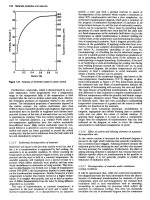
Modern ammonia plant is constructed as large tonnage plant with capacities ranging from min.
600 Te/day to 1000–3000 Te/day and is mainly based on N.G. or naphtha or LSHS as feed stock.
The price of N.G./LSHS/Napfha per million Kcal/BTU is a key factor in economics of ammonia plant
and fixes the criteria of plant design basis and economics, of payout time, I.R.R, R.O.I. etc. In Fig.
1 and Fig. 2 block diagrams for ammonia synthesis process based on N.G. and LSHS is given.
7. UREA PLANT
Now a days most urea plants are designed, based on Stamicarbon’s CO
2
stripping process or
Snadom’s ammonia stripping process. Toyo Engg. Corpn’s total soln. recycle, ACES process is used
in many plants and also Technimont’s IDR process which uses both CO
2
and ammonia stripping
finds its use in some plants.
Process : Conventional Total Soln. Recycle
Preheated liquid ammonia and CO
2
gases under 190–200 Kg/cm
2
press are reacted in an
adiabatic reactor at 180–190°C in presence of recycled unconverted carbamate soln. The reactor feed
ratio of NH
3
: CO
2
: H
2
O is 3.5–4 : 1 : 0.5 to 0.6.
Reaction : 2NH
3
+ CO
2
→
NH
4
COONH
2
∆H = –38 Kcal/Kgmole
NH
4
COONH
2
= NH
2
CONH
2
+ H
2
O ∆H = 5 Kcal/Kgmole
Urea
Overall reaction :
2NH
3
+ CO
2
= NH
2
CONH
2
+ H
2
O ∆H = –33 Kcal/Kgmol
A CO
2
conversion efficiency of 60–70% is achieved in the reactor and the unconverted
ammonium carbamate decomposed in 2/3 stages. The decomposed gases (NH
3
, CO
2
and H
2
O) are
absorbed in corresponding absorbers with rectification for separation of excess ammonia at 2nd stage
(16–17) Kg/cm
2
; recycle soln. from 3rd stage absorber is successibly sent to next higher stages and
finally pumped from 1st stage condensor to reactor by H.P. carbamate recycle pump. Excess
ammonia vapour recovered from 2nd stage absorber rectification stage at top is condensed and
recycled back to reactor by H.P. NH
3
feed pump along with makeup NH
3
duly preheated. Make up
CO
2
gas is compressed in centrifugal/reciprocating compressor and fed to reactor. The 70–75%
dilute urea solution from 3rd stage distiller is concentrated in two stage vacuum concentration to
98.5–99% urea melt and prilled in a I.D. prilling tower having rotating (370–380 rpm) bucket sprayer
(1–1.3 mm hole). The specific load in a prilling tower is 0.17– 0.19 tonnes/m
2
and air rate = 1000
NM
3
/te with air velocity of about 0.47 m/sec.
FERTILISERS 13
Stamicarbon CO
2
Stripping Process
1st developed by Stamicarbon NV in 1965. It is based on Henry’s law.
The equation which governs the principle of stripping gases, CO
2
/ammonia in decomposition
of unconverted carbamate, is given below:
2NH
3
+ CO
2
NH
4
OCONH
2
∆H = –38 Kcal/Kgmol.
Eqn.
CKCC
carb. eq.
NH
CO
3
2
2
=
where K
eq.
is the equilibrium constant for the above reaction and C
carb
C
NH
3
2
C
CO
2
are the concentrations
of carbamate, NH
3
and CO
2
respectively.
If CO
2
gas is passed through the solution containing unconverted carbamate, the above reaction
becomes
C
carb
= K
eq
× O
2
×
2
CO
C
(due to high CO
2
conc. ion, NH
3
concentrate becomes 0 or negligible)
= 0
Therefore, carbamate conc. will be 0 or nearly so when CO
2
is used as a stripping gas. The
operating pressure in the syn. loop consisting of reactor, stripper and carbamate condensers is 150
atm and NH
3
: CO
2
ratio in reactor is 2.8 and conversion of CO
2
to urea is around 58–60%. The
NH
3
: CO
2
ratio is the syn. loop is 2 which ensures smaller NH
3
feed pump. The overall CO
2
conversion efficiency is 80–85%. The stripper is having vertical titanium tubes through which reactor
effluent descends in a thin film and the tubes are heated outside with steam at 160–180°C. All CO
2
gases at 150 Kg/cm
2
are passed upwards through the tubes from bottom and the stripped reactor
effluent is devoid of 90% CO
2
and NH
3
and hence carbamate. The stripped NH
3
and CO
2
gases along
with water vapour are led into carbamate condenser which is also fed with an amount of ammonia
through an ejector which draws reactor effluent equivalent to the amount of CO
2
introduced into the
stripper bottom. The ejector effluent containing make up ammonia and reactor effluent flows to the
falling film type carbamate condenser where condensation takes place and the heat evolved is used
for waste heat steam generation at low pressure. The outlet stream from HP condenser containing
recycle carbamate solution together with NH
3
and CO
2
gases, flows into the reactor. The stripper
exit solution after pressure reduction, is led to rectifying column at low pressure where urea solution
is removed of residual carbamate and dilute urea sol. 72–75% is led into two stage vacuum concentrators
at prilling top and 99% urea melt from 2nd stage concentrator is prilled using spinning buckets
sprayer in prilling tower with induced airflow. There is only one recycle stage after HP syn. loop.
Since the process works on low excess ammonia, corrosion in HP syn. loop is prevented by
introducing 2–3% oxygen along with make up CO
2
gas. The better corrosion resistant material
(Titanium tubes) in stripper and condensor is used; inert gases are removed from reactor top in inert
washing tower and condensed NH
3
and CO
2
is recycled to H.P. condenser.
Condenser. The vapours from rectifying column are condensed in a condenser and remaining
NH
3
and CO
2
along with inerts are washed in inert washing column with condensate from vacuum
section. A part of condensate from vacuum section is hydrolysed in a urea hydrolyser and ammonia
and carbon dioxide vapours are recovered.
14 REFERENCE BOOK ON CHEMICAL ENGINEERING
The reactor volume is slightly bigger and vapour pocket exits at top. The reactor is provided
with sieve trays for better vapour liquid mixing and to prevent back flow. Stamicarbon CO
2
stripping
process is being used in a large number of urea plants in the world. The plant is economical as capital
cost and variable cost are lower.
Snam Progetti NH
3
Stripping Process
The principle of the process is given by the following equations :
(A) NH
2
COONH
4
→
←
CO(NH
2
)
2
+ H
2
O
ammon. carbamate urea
(B) 2NH
3
+ CO
2
→
←
NH
2
COONH
4
Ammon. carbamate
(C)
2
32
0.53 Ps
P=
3[NH].[CO]
where P = dissociation Pressure of liquid carbamate.
In this process pressure in the syn. loop using ammonia as stripping agent of reactor, NH
3
stripper (titanium tubes) and H.P. carbamate condenser, is maintained at 150 atm; NH
3
: CO
2
in the
reactor is 3 : 8 and temperature 185°C with conversion efficiency of 65–67%. Due to high NH
3
:
CO
2
ratio, there is high residual NH
3
content in the stripped solution leaving the stripper. The overall
CO
2
conversion efficiency in the syn. loop is 85%. Two carbamate decomposition and recovery
stages, down stream of syn. loop, and a separate NH
3
recovery unit as pure component have been
provided.
Two H.P. condensers have been provided with steam recovery at 4.5 atm and 6 atm respectively.
All CO
2
with 0.3% oxygen for condensers passivation-with little by pass to stripper (as more heat
is produced than required to maintain reactor temp.) to which reactor effluent from top enters. The
reactor effluent passes through the stripper against an ascending stream of NH
3
vapour from NH
3
evaporation section. Steam at 25 atm is passed in the shell side of stripper operating at 170–180°C.
The stripper effluent contains only 2% carbamate and followed by two stages of decomposition and
recovery at 17 and 3.5 atm and the 75% urea solution obtained is concentrated in 2 stage vacuum
concentrator to get 99.5% urea melt which is sprayed from a rotating bucket (300 rpm) in an
induced draft prilling tower and prills at 50°C is obtained from bottom. Free fall of urea melt in
P/T is 30 m and overall ht. of P.T with vacuum concentrators and dedusting system at top of P.T
is about 44 m.
The stripped NH
3
, CO
2
and H
2
O gases are condensed in 1st H.P. condenser with steam raising
at 6 atm, and outlet condensed carbamate, along with uncondensed vapour, is fed into 2nd H.P.
condenser where full condensation of gases occur and then recycled to recover via H.P. ejector
operated by H.P. ammonia feed from ammonia pump. The 1st stage recycle solution from H.P.
absorber is pumped to no. 1 H.P. condenser and L.P. condenser weak solution is pumped to H.P.
condenser. NH
3
and CO
2
is absorbed from vacuum condensate and recycled back to L.P. condenser.
Fig. 3.