steam plant operation
Bạn đang xem bản rút gọn của tài liệu. Xem và tải ngay bản đầy đủ của tài liệu tại đây (16.19 MB, 795 trang )
Chapter
11
1
1
Steam and Its Importance
In today’s modern world, all societies are involved to various
degrees with technological breakthroughs that are attempting to
make our lives more productive and more comfortable. These tech-
nologies include sophisticated electronic devices, the most promi-
nent of which are computer systems. Many of the systems in our
modern world depend on a reliable and relatively inexpensive energy
source—electricity. In fact, inexpensive and reliable electricity is
critical to the sustained economic growth and security of the United
States and of the rest of the world.
The United States depends on reliable, low-cost, and abundant
energy. Energy drives the economy, heats homes, and pumps water.
The efficient use and production of electricity and effective conserva-
tion measures are paramount in ensuring low-cost energy. As an
example, the United States uses about 10 percent more energy today
than it did in 1973, yet there are more than 20 million additional
homes and 50 million more vehicles, and the gross national product
(GNP) is 50 percent higher.
1
With the availability of electricity providing most of the industrial-
ized world a very high degree of comfort, the source of this electricity
and the means for its production are often forgotten. It is the power
plant that provides this critical energy source, and in the United
States approximately 90 percent of the electricity is produced from
power plants that use steam as an energy source, with the remaining
10 percent of the electricity produced primarily by hydroelectric
power plants. In other parts of the world, similar proportions are
common for their electric production.
1
Position Statement on Energy by the National Society of Professional Engineers.
Ch01_Lammers_1418466 10/8/04 11:33 AM Page 1
2 Chapter One
The power plant is a facility that transforms various types of energy
into electricity or heat for some useful purpose. The energy input to
the power plant can vary significantly, and the plant design to accom-
modate this energy is drastically different for each energy source. The
forms of this input energy can be as follows:
1. The potential energy of an elevated body of water, which, when
used, becomes a hydroelectric power plant.
2. The chemical energy that is released from the hydrocarbons con-
tained in fossil fuels such as coal, oil, or natural gas, which
becomes a fossil fuel fired power plant.
3. The solar energy from the sun, which becomes a solar power plant.
4. The fission or fusion energy that separates or attracts atomic parti-
cles, which becomes a nuclear power plant.
With any of these input sources, the power plant’s output can take
various forms:
1. Heat for a process or for heating
2. Electricity that is subsequently converted into other forms of energy
3. Energy for transportation such as for ships
In these power plants, the conversion of water to steam is the pre-
dominant technology, and this book will describe this process and the
various systems and equipment that are used commonly in today’s
operating steam power plants.
Each power plant has many interacting systems, and in a steam
power plant these include fuel and ash handling, handling of combus-
tion air and the products of combustion, feedwater and condensate,
steam, environmental control systems, and the control systems that
are necessary for a safe, reliable, and efficiently run power plant. The
eighth edition of Steam-Plant Operation continues to blend descrip-
tions and illustrations of both new and older equipment, since both
are in operation in today’s power plants.
1.1 The Use of Steam
Steam is a critical resource in today’s industrial world. It is essential
for the production of paper and other wood products, for the preparation
and serving of foods, for the cooling and heating of large buildings, for
driving equipment such as pumps and compressors, and for powering
ships. However, its most important priority remains as the primary
source of power for the production of electricity.
Ch01_Lammers_1418466 10/8/04 11:33 AM Page 2
Steam and Its Importance 3
Steam is extremely valuable because it can be produced anywhere
in the world by using the heat that comes from the fuels that are
available in the area. Steam also has unique properties that are
extremely important in producing energy. Steam is basically recycled,
from steam to water and then back to steam again, all in a manner
that is nontoxic in nature.
The steam plants of today are a combination of complex engineered
systems that work to produce steam in the most efficient manner that
is economically feasible. Whether the end product of this steam is elec-
tricity, heat, or a steam process required to develop a needed product
such as paper, the goal is to have that product produced at the lowest
cost possible. The heat required to produce the steam is a significant
operating cost that affects the ultimate cost of the end product.
In every situation, however, the steam power plant must first
obtain heat. This heat must come from an energy source, and this
varies significantly, often based on the plant’s location in the world.
These sources of heat could be
1. A fossil fuel—coal, oil, or natural gas
2. A nuclear fuel such as uranium
3. Other forms of energy, which can include waste heat from exhaust
gases of gas turbines; bark, wood, bagasse, vine clippings, and
other similar waste fuels; by-product fuels such as carbon monoxide
(CO), blast furnace gas (BFG), or methane (CH
4
); municipal solid
waste (MSW); sewage sludge; geothermal energy; and solar energy
Each of these fuels contains potential energy in the form of a heating
value, and this is measured in the amount of British thermal units
(Btus) per each pound or cubic feet of the fuel (i.e., Btu/lb or Btu/ft
3
)
depending on whether the fuel is a solid or a gas. (Note: A British
thermal unit is about equal to the quantity of heat required to raise
one pound of water one degree Fahrenheit.)
This energy must be released, and with fossil fuels, this is done
through a carefully controlled combustion process. In a nuclear power
plant that uses uranium, the heat energy is released by a process
called fission. In both cases the heat is released and then transferred
to water. This can be done in various ways, such as through tubes
that have the water flowing on the inside. As the water is heated, it
eventually changes its form by turning into steam. As heat is continu-
ally added, the steam reaches the desired temperature and pressure
for the particular application.
The system in which the steam is generated is called a boiler, or often
commonly called a steam generator. Boilers can vary significantly in
size and design. A relatively small one supplies heat to a building, and
Ch01_Lammers_1418466 10/8/04 11:33 AM Page 3
4 Chapter One
other industrial-sized boilers provide steam for a process. Very large
systems produce enough steam at the proper pressure and temperature
to result in the generation of 1300 megawatts (MW) of electricity in an
electric utility power plant. Such a large power plant would provide
the electric needs for over 1 million people.
Small boilers that produce steam for heating or for a process are
critical in their importance in producing a reliable steam flow, even
though it may be saturated steam at a pressure of 200 psig and a steam
flow of 5000 lb/h. This then can be compared with the large utility
boiler that produces 10 million pounds of superheated steam per hour
at pressures and temperatures exceeding 3800 psig and 1000°F. To
the operator of either size plant, reliable, safe, and efficient operation
is of the utmost importance. The capacity, pressure, and temperature
ranges of boilers and their uniqueness of design reflect their applica-
tions and the fuel that provides their source of energy.
Not only must the modern boiler produce steam in an efficient manner
to produce power (heat, process, or electricity) with the lowest opera-
tional cost that is practical, but also it must perform in an environmen-
tally acceptable way. Environmental protection is a major consideration
in all modern steam generating systems, where low-cost steam and
electricity must be produced with a minimum impact on the environ-
ment. Air pollution control that limits the emissions of sulfur dioxide
(SO
2
) and other acid gases, particulates, and nitrogen oxides (NO
x
) is
a very important issue for all combustion processes.
The systems that are required to meet the environmental emissions
requirements are quite complex, and many of these systems are
described in Chap. 12. There is no question that protecting the environ-
ment is very important and that it is a very emotional issue. Many
media reports and many environmental groups have presented infor-
mation from which one could conclude that there is a crisis in the
United States regarding air quality and that additional coal burning
cannot be tolerated. The evidence definitively contradicts this mis-
leading information.
In accordance with data from the Environmental Protection Agency
(EPA), the emissions of most pollutants peaked around 1970. Since this
peak, the air quality in the United States has improved by 30 percent.
This improvement came about even though the population increased
about 30 percent, the gross domestic product (GDP) nearly doubled, and
the use of fossil fuels increased dramatically. In particular, coal use by
power producers nearly tripled from 320 million tons in 1970 to nearly
900 million tons in 2000, yet the air became dramatically cleaner.
According to the EPA, the following are the improvements in the
average air quality from a period of 1989 to 1998:
Ch01_Lammers_1418466 10/8/04 11:33 AM Page 4
Steam and Its Importance 5
■
SO
2
emissions down 39 percent
■
CO emissions down 39 percent
■
Particulate emissions down 25 percent
■
NO
x
emissions down 14 percent
The older coal-fired boilers often have been mislabeled as gross pol-
luters, but because of the requirements imposed by the Clean Air Act,
emissions from many of these plants are lower than those mandated
by law.
When power plant emissions have been evaluated for particulate mat-
ter and SO
2
since 1970, the statistics are quite impressive. Particulate
emissions have been reduced nearly 94 percent, and SO
2
reductions are
70 percent. The dramatic reduction in particulates results primarily
from replacing older electrostatic precipitators (ESPs) with fabric filters
or high-efficiency ESPs. The use of flue gas desulfurization (FGD) sys-
tems has resulted in the reduction of SO
2
emissions.
The resulting air quality improvements in the United States come
with a significant price tag because over $40 billion has been invested
over the past 25 years in flue gas desulfurization (FGD) systems, fabric
filters, high-efficiency ESPs, selective catalytic reduction (SCR) systems
for the reduction of NO
x
, and other environmental systems. Because
of these additions, the cost of electricity in many areas has increased
approximately 10 percent.
Yet, despite these significant improvements in air quality, additional
restrictions are being imposed. These include restrictions on small par-
ticulate matter, mercury, and CO
2
, and systems are being developed to
meet these new regulations.
Low NO
x
burners, combustion technology, and supplemental sys-
tems have been developed for systems fired by coal, oil, or natural
gas. These systems have met all the requirements that have been
imposed by the U.S. Clean Air Act, and as a result, NO
x
levels have
been reduced significantly from uncontrolled levels.
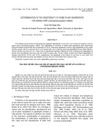
1.2 The Steam-Plant Cycle
The simplest steam cycle of practical value is called the Rankine
cycle, which originated around the performance of the steam engine.
The steam cycle is important because it connects processes that allow
heat to be converted to work on a continuous basis. This simple cycle
was based on dry saturated steam being supplied by a boiler to a power
unit such as a turbine that drives an electric generator. (Note: Refer to
Chap. 3. Dry saturated steam is at the temperature that corresponds
Ch01_Lammers_1418466 10/8/04 11:33 AM Page 5
to the boiler pressure, is not superheated, and does not contain mois-
ture.) The steam from the turbine exhausts to a condenser, from
which the condensed steam is pumped back into the boiler. It is also
called a condensing cycle, and a simple schematic of the system is
shown in Fig. 1.1.
This schematic also shows heat (Q
in
) being supplied to the boiler
and a generator connected to the turbine for the production of elec-
tricity. Heat (Q
out
) is removed by the condenser, and the pump supplies
energy (W
p
) to the feedwater in the form of a pressure increase to
allow it to flow through the boiler.
A higher plant efficiency is obtained if the steam is initially super-
heated, and this means that less steam and less fuel are required for
a specific output. (Superheated steam has a temperature that is above
that of dry saturated steam at the same pressure and thus contains
more heat content, called enthalpy, Btu/lb.) If the steam is reheated
and passed through a second turbine, cycle efficiency also improves, and
moisture in the steam is reduced as it passes through the turbine.
This moisture reduction minimizes erosion on the turbine blades.
When saturated steam is used in a turbine, the work required to rotate
the turbine results in the steam losing energy, and a portion of the steam
condenses as the steam pressure drops. The amount of work that can be
done by the turbine is limited by the amount of moisture that it can
accept without excessive turbine blade erosion. This steam moisture
content generally is between 10 and 15 percent. Therefore, the mois-
ture content of the steam is a limiting factor in turbine design.
With the addition of superheat, the turbine transforms this additional
energy into work without forming moisture, and this energy is basically
all recoverable in the turbine. A reheater often is used in a large utility
6 Chapter One
Figure 1.1 Schematic diagram for a Rankine cycle.
Turbine
Boiler
Q
in
Q
out
Pump Condenser
W
p
Generator
Ch01_Lammers_1418466 10/8/04 11:33 AM Page 6
Steam and Its Importance 7
plant because it adds additional steam energy to the low-pressure por-
tion of the turbine, thereby increasing the overall plant efficiency.
By the addition of regenerative feedwater heating, the original
Rankine cycle was improved significantly. This is done by extracting
steam from various stages of the turbine to heat the feedwater as it is
pumped from the condenser back to the boiler to complete the cycle. It
is this cycle concept that is used in modern power plants, and the
equipment and systems for it will be described in this book.
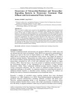
1.3 The Power Plant
The steam generator or boiler is a major part of the many systems
that comprise a steam power plant. A typical pulverized-coal-fired
utility power plant is shown schematically in Fig. 1.2. The major sys-
tems of this power plant can be identified as
1. Coal receipt and preparation
2. Coal combustion and steam generation
3. Environmental protection
4. Turbine generator and electric production
5. Condenser and feedwater system
6. Heat rejection, including the cooling tower
In this example, the fuel handling system stores the coal supply,
prepares the fuel for combustion by means of pulverization, and then
transports the pulverized coal to the boiler. A forced-draft (FD) fan
supplies the combustion air to the burners, and this air is preheated
in an air heater, which improves the cycle efficiency. The heated air is
also used to dry the pulverized coal. A primary air fan is used to sup-
ply heated air to the pulverizer for coal drying purposes and is the
source of the primary air to the burners as the fuel-air mixture flows
from the pulverizers to the burners. The fuel-air mixture is then
burned in the furnace portion of the boiler.
The boiler recovers the heat from combustion and generates steam
at the required pressure and temperature. The combustion gases are
generally called flue gas, and these leave the boiler, economizer, and
finally the air heater and then pass through environmental control
equipment. In the example shown, the flue gas passes through a partic-
ulate collector, either an electrostatic precipitator or a bag filterhouse,
to a sulfur dioxide (SO
2
) scrubbing system, where these acid gases are
removed, and then the cleaned flue gas flows to the stack through an
induced-draft (ID) fan. Ash from the coal is removed from the boiler
and particulate collector, and residue is removed from the scrubber.
Ch01_Lammers_1418466 10/8/04 11:33 AM Page 7
8
Figure 1.2 Schematic of a typical pulverized coal–fired utility power plant. Reheater
, ash
and reagent handling, and sludge disposal are not shown. (Babcock & Wilcox, a McDermott
company.)
Ch01_Lammers_1418466 10/8/04 11:33 AM Page 8
Steam and Its Importance 9
Steam is generated in the boiler under carefully controlled condi-
tions. The steam flows to the turbine, which drives a generator for the
production of electricity and for distribution to the electric system at
the proper voltage. Since the power plant has its own electrical needs,
such as motors, controls, and lights, part of the electricity generated
is used for these plant requirements.
After passing through the turbine, the steam flows to the condenser,
where it is converted back to water for reuse as boiler feedwater. Cooling
water passes through the condenser, where it absorbs the rejected
heat from condensing and then releases this heat to the atmosphere
by means of a cooling tower. The condensed water then returns to the
boiler through a series of pumps and heat exchangers, called feedwater
heaters, and this process increases the pressure and temperature of the
water prior to its reentry into the boiler, thus completing its cycle
from water to steam and then back to water.
The type of fuel that is burned determines to a great extent the
overall plant design. Whether it be the fossil fuels of coal, oil, or natural
gas, biomass, or by-product fuels, considerably different provisions
must be incorporated into the plant design for systems such as fuel
handling and preparation, combustion of the fuel, recovery of heat, foul-
ing of heat-transfer surfaces, corrosion of materials, and air pollution
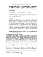
control. Refer to Fig. 1.3, where a comparison is shown of a natural
gas–fired boiler and a pulverized-coal-fired boiler, each designed for
the same steam capacity, pressure, and temperature. This comparison
only shows relative boiler size and does not indicate the air pollution
control equipment that is required with the coal-fired boiler, such as
an electrostatic precipitator and an SO
2
scrubber system. Such systems
are unnecessary for a boiler designed to burn natural gas.
In a natural gas–fired boiler, there is minimum need for fuel stor-
age and handling because the gas usually comes directly from the
pipeline to the boiler. In addition, only a relatively small furnace is
required for combustion. Since natural gas has no ash, there is no
fouling in the boiler because of ash deposits, and therefore the boiler
design allows heat-transfer surfaces to be more closely spaced. The
combination of a smaller furnace and the closer spacing results in a
more compact boiler design. The corrosion allowance is also relatively
small, and the emissions control required relates primarily to the
nitrogen oxide (NO
x
) that is formed during the combustion process.
The boiler designed for natural gas firing is therefore a relatively
small and economical design.
The power plant becomes much more complex when a solid fuel
such as coal is burned. Coal and other solid fuels have a high percent-
age of ash, which is not combustible, and this ash must be a factor in
designing the plant. A coal-fired power plant must include extensive
Ch01_Lammers_1418466 10/8/04 11:33 AM Page 9
10 Chapter One
fuel handling, storage, and preparation facilities; a much larger furnace
for combustion; and wider spaced heat-transfer surfaces. Additional
components are also required:
1. Sootblowers, which are special cleaning equipment to reduce the
impact of fouling and erosion
2. Air heaters, which provide air preheating to dry fuel and enhance
combustion
3. Environmental control equipment such as electrostatic precipitators,
bag filterhouses, and SO
2
scrubbers
4. Ash handling systems to collect and remove ash
5. Ash disposal systems including a landfill
The units shown in Fig. 1.3 are designed for the same steam capacity,
but one is designed for natural gas firing and the other is designed for
pulverized coal firing. Although the comparison of the two units
shows only a relative difference in the height of the units, both the
depth and the width of the coal-fired unit are proportionately larger
as well.
The operators of power plants are continually investigating various
means to increase their revenues by increasing the efficiency of their
plants, by reducing their costs, and by creating other salable products.
This all must be accomplished by reducing the impact of the operation
on the environment. For example, one utility has taken unique steps
in the handling and disposing of fly ash.
This utility has constructed a storage dome that holds approxi-
mately 85,000 tons of fly ash, which is the amount of fly ash produced
from this plant in 2 months of operation. The storage dome is filled in
the winter and early spring so that the maximum amount of fly ash is
available and used in place of cement for the production of concrete in
the summer months when many construction projects are active.
Fly ash is an excellent substitute for cement in concrete. With its use,
the following improvements are found in concrete: strength, durability,
permeability, and susceptibility to thermal cracking and sulfate attack.
In the past, small amounts of fly ash have been used in concrete, but
recent studies conclude that concrete containing 50 percent fly ash
can be used, and the results show the significant improvements iden-
tified above.
The use of fly ash not only reduces the cost of the concrete but also
reduces the landfill costs for this waste product, which must be dis-
posed in some manner. Therefore, the use of fly ash in concrete and
other unique ideas will continue to be investigated.
Ch01_Lammers_1418466 10/8/04 11:33 AM Page 10
Figure 1.3 Comparison of (a) a natural gas–fired boiler and (b) a pulverized coal-fired boiler,
each producing the steam at the same capacity, pressure, and temperature. (
Babcock &
Wilcox, a McDermott company.)
11
Ch01_Lammers_1418466 10/8/04 11:33 AM Page 11
12 Chapter One
1.4 Utility Boilers for Electric Power
Both in the United States and worldwide, the majority of electric
power is produced in steam power plants using fossil fuels and steam
turbines. Most of the electric production comes from large electric
utility plants, although many of the newer plants are much smaller
and owned and operated by independent power producers (IPPs).
Until the 1980s, the United States and other Western nations
developed large electrical networks, primarily with electric utilities.
Over the past several decades in the United States, the increased
electricity annual demand of about 2 percent has been met through
independent power producers. However, the United States is not
dependent on this IPP capacity. The average electricity reserve mar-
gin is 20 percent. This allows the opportunity to investigate the possi-
ble changes of established institutions and regulations, to expand
wheeling of power to balance regional supply, and to demand and sat-
isfy these low incremental capacity needs in less expensive ways.
(Note: Wheeling is the sale of power across regions and not restricted
to the traditional local-only supply.)
However, this sale of power across regions has shown that there are
problems with the electrical distribution system, as evidenced by sev-
eral critical blackouts in recent years in the United States.
Because power plants have become, in many cases, remote from the
electricity user, a more demanding electrical grid is required, as well
as a managing computer and distribution complex to ensure that elec-
tricity is transmitted to the user reliably and efficiently. The black-
outs that have occurred have resulted in a critical evaluation of the
electrical grid in the United States and a determination for the require-
ments to make it more reliable. It will be an expensive but necessary
process.
Many developing countries do not have the luxury of having a
reserve margin. In fact, their electric supply growth is just meeting
demand, and in many cases, the electric supply growth is not close to
meeting demand. Power outages are frequent, and this has a serious
impact on the local economy.
As an average for large utility plants, a kilowatt-hour (kWh) of elec-
tricity is produced for each 8500 to 9500 Btus that are supplied from
the fuel, and this results in a net thermal efficiency for the plant of 36
to 40 percent. These facilities use steam-driven turbine generators
that produce electricity up to 1300 MW, and individual boilers are
designed to produce steam flows ranging from 1 million to 10 million
lb/h. Modern plants use cycles that have, at the turbine, steam pres-
sures ranging from 1800 to 3500 psi and steam temperatures from
950 to 1000°F and at times over 1000°F.
Ch01_Lammers_1418466 10/8/04 11:33 AM Page 12
Steam and Its Importance 13
In the United States, approximately 3900 billion kWh of electricity
is generated from the following energy sources:
Coal 51%
Oil 2
Natural gas 16
Nuclear 20
Hydroelectric 8
Geothermal and others 3
Total 100%
Therefore, nearly 70 percent of the electric production results from
steam generators that use the fossil fuels of coal, oil, or natural gas. A
portion of the energy from natural gas powers gas turbine cogenera-
tion plants that incorporate a steam cycle. Since nuclear plants also
use steam to drive turbines, when added to the fossil fuel plant total,
almost 90 percent of electricity production comes from steam power
plants, which certainly reflects the importance of steam.
The overwhelmingly dominant fossil fuel used in modern U.S. power
plants is coal, since it is the energy source for over 50 percent of the elec-
tric power produced. There are many types of coal, as discussed in Chap.
4, but the types most often used are bituminous, subbituminous, and
lignite. Although it is expected that natural gas will be the fuel choice for
some future power plants, such as gas turbine combined-cycle facilities,
coal will remain the dominant fuel for the production of electricity in the
foreseeable future. As discussed later, the use of natural gas will contin-
ue to depend on its availability and its cost. Assuming that availability
and cost are favorable, some predict that the natural gas share of elec-
tricity production could rise to near 30 percent by the year 2025, with
electricity production from coal being reduced to 47 percent.
It is the belief of some in the power industry that the approximate
20 percent of the electricity that is now produced in the United States
from nuclear power will be reduced to about 10 percent over the next
several decades. If this occurs, the majority, if not all, of this power
will be replaced with coal-fired units. This additional coal-fired capacity
may come from reactivated coal-fired plants that are currently in a
reserve status, as well as new coal-fired units.
On the other hand, others believe that with nuclear power plants
showing a record of better performance with increasing availability
factors, there may be a growing interest to implement new nuclear
power technologies for the construction of additional capacity in the
future. Operating costs, which are greatly affected by fuel costs, as
Ch01_Lammers_1418466 10/8/04 11:33 AM Page 13
well as environmental requirements, will determine the future mix of
energy sources.
On a worldwide basis, a similar pattern is present as in the United
States, with coal being the predominant fuel for the production of
electricity:
Coal 44%
Oil 10
Natural gas 8.5
Nuclear 17
Hydroelectric 20
Other 0.5
Total 100.0%
Although many newer and so-called sophisticated technologies often
get the headlines for supplying the future power needs of the world,
electric power produced from generated steam, with the use of fossil
fuels or with the use of nuclear energy, results in the production of 80
to 90 percent of the world’s energy requirements. Therefore, steam
continues to have a dominant role in the world’s economic future.
1.4.1 Coal-fired boilers
Coal is the most abundant fuel in the United States and in many other
parts of the world. In the United States, the supply of coal resources is
estimated to be nearly 500 years. The benefit of its high availability,
however, is offset by the fact that it is the most complicated fuel to burn.
Many problems occur with the systems required to combust the fuel effi-
ciently and effectively as well as the systems that are required to handle
the ash that remains after combustion. Even with similar coals, designs
vary from even one boiler designer because of operating experience and
testing. For different boiler designers, significant differences in design
are apparent because of the designers’ design philosophy and the experi-
ence gained with operating units.
Despite all the complications that the burning of coal involves, it pre-
sents some very interesting statistics, as developed by the
International Energy Agency. Approximately 25 percent of the world’s
coal reserves are located in the United States. This represents 90 per-
cent of the total of U.S. energy reserves, which include natural gas and
oil. As noted previously, over 50 percent of the total electricity produc-
tion in the United States is generated from coal. Coal production in the
United States has increased from 890 million tons in 1980 to 1121 mil-
lion tons in 2001. By the year 2020, coal production is expected to be
nearly 1400 million tons.
14 Chapter One
Ch01_Lammers_1418466 10/8/04 11:33 AM Page 14
Steam and Its Importance 15
The cost of a megawatt of energy that is produced by coal ranges from
$20 to $30/MW. Compare this with electricity produced from natural
gas, which ranges from $45 to $60/MW. The economic benefits are
significant.
However, the environmental control aspects of coal firing present
complexities. These include both social and political difficulties when
trying to locate and to obtain a permit for a coal-fired plant that has
atmospheric, liquid, and solid emissions that have to be taken into
consideration in the plant design. Also, as noted previously, there are
a wide variety of coals, each with its own characteristics of heating
value, ash, sulfur, etc., that have to be taken into account in the boiler
design and all its supporting systems. For example, coal ash can vary
from 5 to 25 percent by weight among various coals. Of the total oper-
ating costs of a coal-fired plant, approximately 60 to 80 percent of the
costs are for the coal itself.
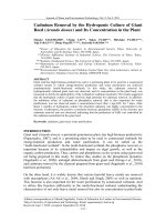
The large coal-fired power plant utilizes pulverized coal firing, as
described in detail in Chaps. 2 and 5. An example of a medium-sized
modern pulverized-coal-fired boiler is shown in Fig. 1.4 and incorporates
low NO
x
burners to meet current emission requirements on nitrogen
oxides (see Chap. 5). This unit is designed to produce 1,250,000 lb/h of
steam at 2460 psig and 1005°F/1005°F (superheat/reheat). This unit has
the coal burners in the front wall and, as part of the NO
x
control system,
has secondary air ports above the burners. This unit has a two gas pass,
three air pass tubular air heater (see Chap. 2). The forced-draft (FD) fan
also takes warm air from the top of the building (above the air heater)
by means of a vertical duct. This design of the combustion air intake
improves the air circulation within the building as well as using all
available heat sources for improving plant efficiency. The environmental
control equipment is not shown in this illustration.
A larger pulverized-coal-fired boiler is shown in Fig. 1.5. This illustra-
tion shows a boiler system and its environmental control equipment
that produces approximately 6,500,000 lb/h of steam for an electrical
output of 860 MW. This is a radiant-type boiler that is designed to
produce both superheated and reheated steam for use in the turbine.
For air heating, it incorporates a regenerative air heater instead of a
tubular air heater. For environmental control, it uses a dry scrubber
for the capture of sulfur dioxide (SO
2
) and a baghouse for the collec-
tion of particulates. The boiler shown is designed for indoor use (see
building enclosing equipment), but depending on location, many boilers
and their auxiliary systems are designed as outside installations.
As noted previously, coal has a dominant role as a critical fuel in the
production of electricity both in the United States and throughout
the world. The use of this fuel brings with it environmental concerns
that encompass the development of cost-effective and efficient systems
Ch01_Lammers_1418466 10/8/04 11:33 AM Page 15
16 Chapter One
for the control of pollutants. These pollutants include emissions of
solid, liquid, and gaseous wastes.
Coal piles can create fugitive dust problems, as well as storm water
runoffs. Following the combustion of coal, emissions of nitrogen
oxides (NO
x
), sulfur dioxide (SO
2
), and particulates all must be con-
trolled within operating permit limits.
There are many projects in development, under construction, and
in operation that will demonstrate innovative ways to use coal effi-
ciently while meeting strict environmental standards.
Figure 1.4 Medium-sized pulverized coal-fired boiler producing 1,250,000 lb/h of steam
at 2460 psig and 1005°F/1005°F (superheat/reheat). (Riley Power, Inc., a Babcock
Power, Inc., company.)
Ch01_Lammers_1418466 10/8/04 11:33 AM Page 16
Figure 1.5 Large utility pulverized coal–fired radiant boiler and environmental control
systems that produce steam for a plant output of 860 MW
. (Babcock & Wilcox, a
McDermott company.)
17
Ch01_Lammers_1418466 10/8/04 11:33 AM Page 17
18 Chapter One
One such project, located in Jacksonville, Florida, is shown in Figs.
1.6 and 1.7. This plant consists of two circulating fluidized bed (CFB)
boilers with each boiler designed to produce approximately 2 million
lb/h of steam at 2500 psig and 1000°F when burning high-sulfur coal
and petroleum coke. The steam flows to a turbine generator, where
each unit produces approximately 300 MW of electricity.
Figure 1.6 Large-scale circulating fluidized bed (CFB) combustion project with coal
storage domes. (Photo courtesy of JEA.)
Figure 1.7 Circulating fluidized bed (CFB) combustion project with coal storage domes.
(Photo courtesy of JEA.)
Ch01_Lammers_1418466 10/8/04 11:33 AM Page 18
Steam and Its Importance 19
The CFB boilers, in combination with additional environmental
control equipment, remove sulfur dioxide (SO
2
), nitrogen oxides
(NO
x
), and particulate matter to meet strict emission requirements.
Removal systems similar to these are described in this book because
they are a critical part of an efficient steam power plant that must
operate within environmental restrictions.
Because of the location of this facility, unique coal storage domes are
used to reduce fugitive dust emissions, as well as storm water runoff.
These domes also keep the coal dry. The domes, as shown in Figs. 1.6
and 1.7, store approximately 60,000 tons of coal and are each 400 ft in
diameter and 140 ft high. These aluminum domes are built with only
outside support structures to eliminate pyramiding of coal dust in the
interior. These coal storage domes are further discussed in Chap. 4.
The ever-increasing demand for electricity and the abundance of
coal in the world require that clean burning technologies be developed
and improved on to ensure that our environment is protected and
that a critical energy resource, coal, is used effectively.
1.4.2 Oil- and gas-fired boilers
The use of oil and gas as fuels for new utility boilers has declined
except for certain areas of the world where these otherwise critical
fuels are readily available and low in cost. Large oil-producing coun-
tries are good examples of places where oil- and gas-fired boilers are
installed. In other areas of the world, their use as fuels for utility boilers
has declined for various reasons: high cost, low availability, and govern-
ment regulations. However, there have been significant improvements
in combined cycle systems that have made the use of oil and more
often natural gas in these systems more cost-effective. In addition,
plants that have these gas turbine cycles are more easily sited than
other types of power plants because of their reduced environmental
concerns. However, in the majority of cases, they depend on a critical
fuel, natural gas, whose availability for the long term may be limited.
1.4.3 Steam considerations
The reheat steam cycle is used on most fossil fuel–fired utility plants.
In this cycle, high-pressure superheated steam from the boiler passes
through the high-pressure portion of the turbine, where the steam
reduces in pressure as it rotates the turbine, and then this lower-
pressure steam returns to the boiler for reheating. After the steam is
reheated, it returns to the turbine, where it flows through the inter-
mediate- and low-pressure portions of the turbine. The use of this
cycle increases the thermal efficiency of the plant, and the fuel costs
are therefore reduced. In a large utility system, the reheat cycle can
Ch01_Lammers_1418466 10/8/04 11:33 AM Page 19
20 Chapter One
be justified because the lower fuel costs offset the higher initial cost of
the reheater, piping, turbine, controls, and other equipment that is
necessary to handle the reheated steam.
1.4.4 Boiler feedwater
When water is obtained from sources that are either on or below the
surface of the earth, it contains, in solution, some scale-forming mate-
rials, free oxygen, and in some cases, acids. These impurities must be
removed because high-quality water is vital to the efficient and reli-
able operation of any steam cycle. Good water quality can improve
efficiency by reducing scale deposits on tubes, it minimizes overall
maintenance, and it improves the availability of the system. All of
this means lower costs and higher revenues.
Dissolved oxygen attacks steel, and the rate of this attack increases
significantly as temperatures increase. By having high chemical con-
centrations or high solids in the boiler water and feedwater, boiler
tube deposition can occur, and solids can be carried over into the
superheater and finally the turbine. This results in superheater tube
failures because of overheating. Deposits and erosion also occur on the
turbine blades. These situations are serious maintenance problems and
can result in plant outages for repairs. The actual maintenance can be
very costly; however, this cost can be greatly exceeded by the loss of
revenues caused by the outage that is necessary to make the repairs.
As steam-plant operating pressures have increased, the water
treatment systems have become more important to obtaining high
availability. This has led to more complete and refined water treat-
ment facilities.
1.5 Industrial and Small Power Plants
Various industries require steam to meet many of their needs: heating
and air conditioning; turbine drives for pumps, blowers, or compressors;
drying and other processes; water heating; cooking; and cleaning. This
so-called industrial steam, because of its lower pressure and tempera-
ture as compared with utility requirements, also can be used to gener-
ate electricity. This can be done directly with a turbine for electric
production only, or as part of a cogeneration system, where a turbine
is used for electric production and low-pressure steam is extracted
from the turbine and used for heating or for some process. The elec-
tricity that is produced is used for in-plant requirements, with the
excess often sold to a local electric utility.
Another method is a combined cycle system, where a gas turbine
is used to generate electric power and a heat recovery system is added
using the exhaust gas from the gas turbine as a heat source. The
Ch01_Lammers_1418466 10/8/04 11:33 AM Page 20
Steam and Its Importance 21
generated steam flows to a steam turbine for additional electric genera-
tion, and this cogeneration results in an improvement in the overall
efficiency. The steam that is generated also can be used as process
steam either directly or when extracted from the system, such as an
extraction point within the turbine.
One of the most distinguishable features of most industrial-type
boilers is a large saturated water boiler bank between the steam
drum and the lower drum. Figure 1.8 shows a typical two-drum
design. This particular unit is designed to burn pulverized coal or fuel
oil, and it generates 885,000 lb/h of steam. Although not shown, this
boiler also requires environmental control equipment to collect partic-
ulates and acid gases contained in the flue gas.
Figure 1.8 Large industrial-type pulverized coal- and oil-fired two-drum boiler.
(Babcock & Wilcox, a McDermott company.)
Ch01_Lammers_1418466 10/8/04 11:34 AM Page 21
22 Chapter One
The boiler bank serves the purpose of preheating the inlet feedwater
to the saturated temperature and then evaporating the water while
cooling the flue gas. In lower-pressure boilers, the heating surface
that is available in the furnace enclosure is insufficient to absorb all
the heat energy that is needed to accomplish this function. Therefore,
a boiler bank is added after the furnace and superheater, if one is
required, to provide the necessary heat-transfer surface.
As shown in Fig. 1.9, as the pressure increases, the amount of heat
absorption that is required to evaporate water declines rapidly, and
the heat absorption for water preheating and superheating steam
increases. See also Table 1.1 for examples of heat absorption at system
pressures of 500 and 1500 psig.
The examples shown in the table assume that the superheat is con-
stant at 100° higher than the saturated temperature for the particu-
lar pressure (see Chap. 3).
It is also common for boilers to be designed with an economizer
and/or an air heater located downstream of the boiler bank in order to
reduce the flue gas temperature and to provide an efficient boiler cycle.
It is generally not economical to distribute steam through long
steam lines at pressures below 150 psig because, in order to minimize
Figure 1.9 Effect of steam pressure on evaporation in industrial
boilers. (Babcock & Wilcox, a McDermott company.)
Ch01_Lammers_1418466 10/8/04 11:34 AM Page 22
Steam and Its Importance 23
the pressure drop that is caused by friction in the line, pipe sizes
must increase with the associated cost increase. In addition, for the
effective operation of auxiliary equipment such as sootblowers and
turbine drives on pumps, boilers should operate at a minimum pres-
sure of 125 psig. Therefore, few plants of any size operate below this
steam pressure. If the pressure is required to be lower, it is common
to use pressure-reducing stations at these locations.
For an industrial facility where both electric power and steam for
heating or a process are required, a study must be made to evaluate
the most economical choice. For example, electric power could be pur-
chased from the local utility and a boiler could be installed to meet
the heating or process needs only. By comparison, a plant could be
installed where both electricity and steam are produced from the
same system.
1.5.1 Fluidized bed boilers
There are various ways of burning solid fuels, the most common of
which are in pulverized-coal-fired units and stoker-fired units. These
designs for boilers in the industrial size range have been in operation
for many years and remain an important part of the industrial boiler
base for the burning of solid fuels. These types of boilers and their
features continue to be described in this book.
Although having been operational for nearly 40 years, but not with
any overall general acceptance, the fluidized bed boiler is becoming
more popular in modern power plants because of its ability to handle
hard-to-burn fuels with low emissions. As a result, this unique design
can be found in many industrial boiler applications and in small utility
power plants, especially those operated by independent power producers
(IPPs). Because of this popularity, this book includes the features of
some of the many designs available and the operating characteristics
of each.
In fluidized bed combustion, fuel is burned in a bed of hot particles
that are suspended by an upward flow of fluidizing gas. The fuel is
generally a solid fuel such as coal, wood chips, etc. The fluidizing gas
TABLE 1.1 Heat Absorption Percentages for Water Preheating,
Evaporation, and of Steam Superheating
500 psig 1500 psig
Water preheating 20% 34%
Evaporation 72 56
Steam superheating 8 10
TOTAL 100% 100%
Ch01_Lammers_1418466 10/8/04 11:34 AM Page 23
is a combination of the combustion air and the flue gas products of
combustion. When sulfur capture is not required, the fuel ash may be
supplemented by an inert material such as sand to maintain the bed.
In applications where sulfur capture is required, limestone is used as
the sorbent, and it forms a portion of the bed. Bed temperature is
maintained between 1550 and 1650°F by the use of a heat-absorbing
surface within or enclosing the bed.
As stated previously, fluidized bed boilers feature a unique concept
of burning solid fuel in a bed of particles to control the combustion
process, and the process controls the emissions of sulfur dioxide (SO
2
)
and nitrogen oxides (NO
x
). These designs offer versatility for the
burning of a wide variety of fuels, including many that are too poor in
quality for use in conventional firing systems.
The state of fluidization in a fluidized bed boiler depends mainly on
the bed particle diameter and the fluidizing velocity. There are two
basic fluid bed combustion systems, the bubbling fluid bed (BFB) and
the circulating fluid bed (CFB), and each operates in a different state
of fluidization.
At relatively low velocities and with coarse bed particle size, the
fluid bed is dense with a uniform solids concentration, and it has a
well-defined surface. This system is called the bubbling fluid bed
(BFB) because the air in excess of that required to fluidize the bed
passes through the bed in the form of bubbles. This system has rela-
tively low solids entrainment in the flue gas.
With the circulating fluid bed (CFB) design, higher velocities and
finer bed particle size are prevalent, and the fluid bed surface
becomes diffuse as solids entrainment increases and there is no
defined bed surface. The recycle of entrained material to the bed at
high rates is required to maintain bed inventory.
It is interesting that the BFB and CFB technologies are somewhat
similar to stoker firing and pulverized coal firing with regard to fluidiz-
ing velocity, but the particle size of the bed is quite different. Stoker
firing incorporates a fixed bed, has a comparable velocity, but has a
much coarser particle size than that found in a BFB. For pulverized-
coal firing, the velocity is comparable with a CFB, but the particle
size is much finer than that for a CFB.
Bubbling fluid bed (BFB) boiler. Of all the fluid bed technologies, the
bubbling bed is the oldest. The primary difference between a BFB
boiler and a CFB boiler design is that with a BFB the air velocity in
the bed is maintained low enough that the material that comprises
the bed (e.g., fuel, ash, limestone, and sand), except for fines, is held
in the bottom of the unit, and the solids do not circulate through the
rest of the furnace enclosure.
24 Chapter One24 Chapter One
Ch01_Lammers_1418466 10/8/04 11:34 AM Page 24