Tài liệu biến tần L201 huyndai
Bạn đang xem bản rút gọn của tài liệu. Xem và tải ngay bản đầy đủ của tài liệu tại đây (5.05 MB, 274 trang )
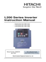
L200 Series Inverter
Instruction Manual
• Single-phase Input 200V Class
• Three-phase Input 200V Class
• Three-phase Input 400V Class
After reading this manual,
keep it handy for future reference.
Hitachi Industrial Equipment Systems Co., Ltd.
Manual Number: NB660XA
April 2004
Cover
L200 Inverter
i
Safety Messages
For the best results with the L200 Series inverter, carefully read this manual and all of
the warning labels attached to the inverter before installing and operating it, and follow
the instructions exactly. Keep this manual handy for quick reference.
Definitions and Symbols
A safety instruction (message) includes a “Safety Alert Symbol” and a signal word or
phrase such as WARNING or CAUTION. Each signal word has the following meaning:
HIGH VOLTAGE: This symbol indicates high voltage. It calls your attention to items
or operations that could be dangerous to you and other persons operation this equipment.
Read the message and follow the instructions carefully.
WA R NI N G: Indicates a potentially hazardous situation that, if not avoided, can result in
serious injury or death.
CAUTION: Indicates a potentially hazardous situation that, if not avoided, can result in
minor to moderate injury, or serious damage to the product. The situation described in
the CAUTION may, if not avoided, lead to serious results. Important safety measures
are described in CAUTION (as well as WARNING), so be sure to observe them.
1 Step 1: Indicates a step in a series of action steps required to accomplish a goal. The
number of the step will be contained in the step symbol.
NOTE: Notes indicate an area or subject of special merit, emphasizing either the
product’s capabilities or common errors in operation or maintenance.
TIP: Tips give a special instruction that can save time or provide other benefits while
installing or using the product. The tip calls attention to an idea that may not be obvious
to first-time users of the product.
Hazardous High Voltage
HIGH VOLTAGE: Motor control equipment and electronic controllers are connected to
hazardous line voltages. When servicing drives and electronic controllers, there may be
exposed components with housings or protrusions at or above line potential. Extreme
care should be taken to protect against shock.
Stand on an insulating pad and make it a habit to use only one hand when checking com-
ponents. Always work with another person in case an emergency occurs. Disconnect
power before checking controllers or performing maintenance. Be sure equipment is
properly grounded. Wear safety glasses whenever working on electronic controllers or
rotating machinery.
ii
General Precautions - Read These First!
WA R NI NG : This equipment should be installed, adjusted, and serviced by qualified
electrical maintenance personnel familiar with the construction and operation of the
equipment and the hazards involved. Failure to observe this precaution could result in
bodily injury.
WA R NI NG : The user is responsible for ensuring that all driven machinery, drive train
mechanism not supplied by Hitachi Industrial Equipment Systems Co., Ltd., and process
line material are capable of safe operation at an applied frequency of 150% of the
maximum selected frequency range to the AC motor. Failure to do so can result in
destruction of equipment and injury to personnel should a single-point failure occur.
WA R NI NG : For equipment protection, install a ground leakage type breaker with a fast
response circuit capable of handling large currents. The ground fault protection circuit is
not designed to protect against personal injury.
WA R NI NG : HAZARD OF ELECTRICAL SHOCK. DISCONNECT INCOMING
POWER BEFORE WORKING ON THIS CONTROL.
WA R NI NG : Wait at least five (5) minutes after turning OFF the input power supply
before performing maintenance or an inspection. Otherwise, there is the danger of
electric shock.
CAUTION: These instructions should be read and clearly understood before working
on L200 series equipment.
CAUTION: Proper grounds, disconnecting devices and other safety devices and their
location are the responsibility of the user and are not provided by Hitachi Industrial
Equipment Systems Co., Ltd.
CAUTION: Be sure to connect a motor thermal disconnect switch or overload device to
the L200 series controller to assure that the inverter will shut down in the event of an
overload or an overheated motor.
HIGH VOLTAGE: Dangerous voltage exists until power light is OFF. Wait at least five
(5) minutes after input power is disconnected before performing maintenance.
WA R NI NG : This equipment has high leakage current and must be permanently (fixed)
hard-wired to earth ground via two independent cables.
L200 Inverter
iii
WA R NI NG : Rotating shafts and above-ground electrical potentials can be hazardous.
Therefore, it is strongly recommended that all electrical work conform to the National
Electrical Codes and local regulations. Installation, alignment and maintenance should
be performed only by qualified personnel.
Factory-recommended test procedures included in the instruction manual should be
followed. Always disconnect electrical power before working on the unit.
CAUTION:
a) Class I motor must be connected to earth ground via low resistive path (< 0.1Ω)
b) Any motor used must be of a suitable rating.
c) Motors may have hazardous moving parts. In this event suitable protection must
be provided.
CAUTION: Alarm connection may contain hazardous live voltage even when inverter is
disconnected. When removing the front cover for maintenance or inspection, confirm
that incoming power for alarm connection is completely disconnected.
CAUTION: Hazardous (main) terminals for any interconnection (motor, contact
breaker, filter, etc.) must be inaccessible in the final installation.
CAUTION: This equipment should be installed in IP54 or equivalent (see EN60529)
enclosure. The end application must be in accordance with BS EN60204-1. Refer to the
section
“Choosing a Mounting Location” on page 2–9. The diagram dimensions are to
be suitably amended for your application.
CAUTION: Connection to field wiring terminals must be reliably fixed having two
independent means of mechanical support. Use a termination with cable support (figure
below), or strain relief, cable clamp, etc.
CAUTION: A double-pole disconnection device must be fitted to the incoming main
power supply close to the inverter. Additionally, a protection device meeting IEC947-1/
IEC947-3 must be fitted at this point (protection device data shown in
“Determining
Wire and Fuse Sizes” on page 2–16).
NOTE: The above instructions, together with any other requirements highlighted in this
manual, must be followed for continued LVD (European Low Voltage Directive)
compliance.
Terminal (ring lug) Cable support
Cable
iv
Index to Warnings and Cautions in This Manual
Cautions and Warnings for Orientation and Mounting Procedures
Wiring - Warnings for Electrical Practices and Wire Specifications
CAUTION: Hazard of electrical shock. Disconnect incoming power
before working on this control. Wait five (5) minutes before removing the
front cover.
2–3
CAUTION: Be sure to install the unit on flame-resistant material such as
a steel plate. Otherwise, there is the danger of fire.
2–9
CAUTION: Be sure not to place any flammable materials near the
inverter. Otherwise, there is the danger of fire.
2–9
CAUTION: Be sure not to let the foreign matter enter vent openings in
the inverter housing, such as wire clippings, spatter from welding, metal
shavings, dust, etc. Otherwise, there is the danger of fire.
2–9
CAUTION: Be sure to install the inverter in a place that can bear the
weight according to the specifications in the text (Chapter 1, Specifica-
tions Tables). Otherwise, it may fall and cause injury to personnel.
2–9
CAUTION: Be sure to install the unit on a perpendicular wall that is not
subject to vibration. Otherwise, it may fall and cause injury to personnel.
2–9
CAUTION: Be sure not to install or operate an inverter that is damaged
or has missing parts. Otherwise, it may cause injury to personnel.
2–9
CAUTION: Be sure to install the inverter in a well-ventilated room that
does not have direct exposure to sunlight, a tendency for high tempera-
ture, high humidity or dew condensation, high levels of dust, corrosive
gas, explosive gas, inflammable gas, grinding-fluid mist, salt damage,
etc. Otherwise, there is the danger of fire.
2–9
CAUTION: Be sure to maintain the specified clearance area around the
inverter and to provide adequate ventilation. Otherwise, the inverter may
overheat and cause equipment damage or fire.
2–10
WARNING: “Use 60/75°C Cu wire only” or equivalent. 2–15
WARNING: “Open Type Equipment.” 2–15
WARNING: “Suitable for use on a circuit capable of delivering not more
than 5,000 rms symmetrical amperes, 240 V maximum.” For models with
suffix N or L.
2–15
L200 Inverter
v
Wiring - Cautions for Electrical Practices
WARNING: “Suitable for use on a circuit capable of delivering not more
than 5,000 rms symmetrical amperes, 480 V maximum.” For models with
suffix H.
2–15
HIGH VOLTAGE: Be sure to ground the unit. Otherwise, there is a
danger of electric shock and/or fire.
2–15
HIGH VOLTAGE: Wiring work shall be carried out only by qualified
personnel. Otherwise, there is a danger of electric shock and/or fire.
2–15
HIGH VOLTAGE: Implement wiring after checking that the power
supply is OFF. Otherwise, you may incur electric shock and/or fire.
2–15
HIGH VOLTAGE: Do not connect wiring to an inverter or operate an
inverter that is not mounted according the instructions given in this
manual. Otherwise, there is a danger of electric shock and/or injury to
personnel.
2–15
WARNING: Make sure the input power to the inverter is OFF. If the drive
has been powered, leave it OFF for five minutes before continuing.
2–21
CAUTION: Fasten the screws with the specified fastening torque in the
table below. Check for any loosening of screws. Otherwise, there is the
danger of fire.
2–17
CAUTION: Be sure that the input voltage matches the inverter specifica-
tions: • Single/Three phase 200 to 240 V 50/60 Hz (up to 2.2kW) for
NFEF/NFU models • Three phase 200 to 240V 50/60Hz (above 2.2kW)
for LFU models • Three phase 380 to 480 V 50/60Hz for HFEF models
2–18
CAUTION: Be sure not to power a three-phase-only inverter with single
phase power. Otherwise, there is the possibility of damage to the inverter
and the danger of fire.
2–18
CAUTION: Be sure not to connect an AC power supply to the output
terminals. Otherwise, there is the possibility of damage to the inverter
and the danger of injury and/or fire.
2–19
Power Input Output to Motor
L200 Inverter
vi
Powerup Test Caution Messages
CAUTION: Remarks for using ground fault interrupter breakers in the
main power supply: Adjustable frequency inverters with CE-filters (RFI-
filter) and shielded (screened) motor cables have a higher leakage current
toward Earth GND. Especially at the moment of switching ON this can
cause an inadvertent trip of ground fault interrupters. Because of the
rectifier on the input side of the inverter there is the possibility to stall the
switch-off function through small amounts of DC current. Please observe
the following: • Use only short time-invariant and pulse current-sensitive
ground fault interrupters with higher trigger current. • Other components
should be secured with separate ground fault interrupters. • Ground fault
interrupters in the power input wiring of an inverter are not an absolute
protection against electric shock.
2–19
CAUTION: Be sure to install a fuse in each phase of the main power
supply to the inverter. Otherwise, there is the danger of fire.
2–19
CAUTION: For motor leads, ground fault interrupter breakers and
electromagnetic contactors, be sure to size these components properly
(each must have the capacity for rated current and voltage). Otherwise,
there is the danger of fire.
2–19
CAUTION: The heat sink fins will have a high temperature. Be careful
not to touch them. Otherwise, there is the danger of getting burned.
2–22
CAUTION: The operation of the inverter can be easily changed from low
speed to high speed. Be sure to check the capability and limitations of the
motor and machine before operating the inverter. Otherwise, there is the
danger of injury.
2–22
CAUTION: If you operate a motor at a frequency higher than the inverter
standard default setting (50Hz/60Hz), be sure to check the motor and
machine specifications with the respective manufacturer. Only operate
the motor at elevated frequencies after getting their approval. Otherwise,
there is the danger of equipment damage and/or injury.
2–22,
2–28
CAUTION: Check the following before and during the powerup test.
Otherwise, there is the danger of equipment damage. • Is the shorting bar
between the [+1] and [+] terminals installed? DO NOT power or operate
the inverter if the jumper is removed. • Is the direction of the motor
rotation correct? • Did the inverter trip during acceleration or decelera-
tion? • Were the rpm and frequency meter readings as expected? • Were
there any abnormal motor vibrations or noise?
2–22
L200 Inverter
vii
Warnings for Configuring Drive Parameters
Cautions for Configuring Drive Parameters
Warnings for Operations and Monitoring
WARNING: When parameter B012, level of electronic thermal setting, is
set to motor FLA rating (Full Load Ampere nameplate rating), the
inverter provides solid state motor overload protection at 115% of motor
FLA or equivalent. If parameter B012 exceeds the motor FLA rating, the
motor may overheat and be damaged. Parameter B012, level of electronic
thermal setting, is a variable parameter.
3–33
CAUTION: Be careful to avoid specifying a braking time that is long
enough to cause motor overheating. If you use DC braking, we recom-
mend using a motor with a built-in thermistor, and wiring it to the
inverter’s thermistor input (see “Thermistor Thermal Protection” on
page 4–25). Also refer to the motor manufacturer’s specifications for
duty-cycle recommendations during DC braking.
3–20
WARNING: Be sure to turn ON the input power supply only after closing
the front case. While the inverter is energized, be sure not to open the
front case. Otherwise, there is the danger of electric shock.
4–3
WARNING: Be sure not to operate electrical equipment with wet hands.
Otherwise, there is the danger of electric shock.
4–3
WARNING: While the inverter is energized, be sure not to touch the
inverter terminals even when the motor is stopped. Otherwise, there is the
danger of electric shock.
4–3
WARNING: If the Retry Mode is selected, the motor may suddenly
restart after a trip stop. Be sure to stop the inverter before approaching the
machine (be sure to design the machine so that safety for personnel is
secure even if it restarts.) Otherwise, it may cause injury to personnel.
4–3
WARNING: If the power supply is cut OFF for a short period of time, the
inverter may restart operation after the power supply recovers if the Run
command is active. If a restart may pose danger to personnel, so be sure
to use a lock-out circuit so that it will not restart after power recovery.
Otherwise, it may cause injury to personnel.
4–3
WARNING: The Stop Key is effective only when the Stop function is
enabled. Be sure to enable the Stop Key separately from the emergency
stop. Otherwise, it may cause injury to personnel.
4–3
WARNING: During a trip event, if the alarm reset is applied and the Run
command is present, the inverter will automatically restart. Be sure to
apply the alarm reset only after verifying the Run command is OFF.
Otherwise, it may cause injury to personnel.
4–3
viii
Cautions for Operations and Monitoring
WARNING: Be sure not to touch the inside of the energized inverter or to
put any conductive object into it. Otherwise, there is a danger of electric
shock and/or fire.
4–3
WARNING: If power is turned ON when the Run command is already
active, the motor will automatically start and injury may result. Before
turning ON the power, confirm that the RUN command is not present.
4–3
WARNING: When the Stop key function is disabled, pressing the Stop
key does not stop the inverter, nor will it reset a trip alarm.
4–3
WARNING: Be sure to provide a separate, hard-wired emergency stop
switch when the application warrants it.
4–3
WARNING: If the power is turned ON and the Run command is already
active, the motor starts rotation and is dangerous! Before turning power
ON, confirm that the Run command is not active.
4–12
WARNING: After the Reset command is given and the alarm reset
occurs, the motor will restart suddenly if the Run command is already
active. Be sure to set the alarm reset after verifying that the Run
command is OFF to prevent injury to personnel.
4–24
CAUTION: The heat sink fins will have a high temperature. Be careful
not to touch them. Otherwise, there is the danger of getting burned.
4–2
CAUTION: The operation of the inverter can be easily changed from low
speed to high speed. Be sure check the capability and limitations of the
motor and machine before operating the inverter. Otherwise, it may cause
injury to personnel.
4–2
CAUTION: If you operate a motor at a frequency higher than the inverter
standard default setting (50Hz/60Hz), be sure to check the motor and
machine specifications with the respective manufacturer. Only operate
the motor at elevated frequencies after getting their approval. Otherwise,
there is the danger of equipment damage.
4–2
CAUTION: It is possible to damage the inverter or other devices if your
application exceeds the maximum current or voltage characteristics of a
connection point.
4–4
CAUTION: Be sure to turn OFF power to the inverter before changing
the SR/SK switch position. Otherwise, damage to the inverter circuitry
may occur.
4–9
CAUTION: Be careful not to turn PID Clear ON and reset the integrator
sum when the inverter is in Run Mode (output to motor is ON). Other-
wise, this could cause the motor to decelerate rapidly, resulting in a trip.
4–28
L200 Inverter
ix
Warnings and Cautions for Troubleshooting and Maintenance
General Warnings and Cautions
WA R NI NG : Never modify the unit. Otherwise, there is a danger of electric shock and/
or injury.
CAUTION: Withstand voltage tests and insulation resistance tests (HIPOT) are
executed before the units are shipped, so there is no need to conduct these tests before
operation.
CAUTION: Do not attach or remove wiring or connectors when power is applied. Also,
do not check signals during operation.
CAUTION: Be sure to connect the grounding terminal to earth ground.
CAUTION: When inspecting the unit, be sure to wait five minutes after tuning OFF the
power supply before opening the cover.
WARNING: Wait at least five (5) minutes after turning OFF the input
power supply before performing maintenance or an inspection. Other-
wise, there is the danger of electric shock.
6–2
WARNING: Make sure that only qualified personnel will perform
maintenance, inspection, and part replacement. Before starting to work,
remove any metallic objects from your person (wristwatch, bracelet,
etc.). Be sure to use tools with insulated handles. Otherwise, there is a
danger of electric shock and/or injury to personnel.
6–2
WARNING: Never remove connectors by pulling on its wire leads (wires
for cooling fan and logic P.C.board). Otherwise, there is a danger of fire
due to wire breakage and/or injury to personnel.
6–2
CAUTION: Do not connect the megger to any control circuit terminals
such as intelligent I/O, analog terminals, etc. Doing so could cause
damage to the inverter.
6–10
CAUTION: Never test the withstand voltage (HIPOT) on the inverter.
The inverter has a surge protector between the main circuit terminals
above and the chassis ground.
6–10
HIGH VOLTAGE: Be careful not to touch wiring or connector terminals
when working with the inverters and taking measurements. Be sure to
place the measurement circuitry components above in an insulated
housing before using them.
6–14
x
CAUTION: Do not stop operation by switching OFF electromagnetic contactors on the
primary or secondary sides of the inverter.
When there has been a sudden power failure while an operation instruction is active, then
the unit may restart operation automatically after the power failure has ended. If there is
a possibility that such an occurrence may harm humans, then install an electromagnetic
contactor (Mgo) on the power supply side, so that the circuit does not allow automatic
restarting after the power supply recovers. If the optional remote operator is used and the
retry function has been selected, this will also cause automatic restarting when a Run
command is active. So, please be careful.
CAUTION: Do not insert leading power factor capacitors or surge absorbers between
the output terminals of the inverter and motor.
CAUTION: MOTOR TERMINAL SURGE VOLTAGE SUPPRESSION FILTER
(For the 400 V CLASS)
In a system using an inverter with the voltage control PWM system, a voltage surge
caused by the cable constants such as the cable length (especially when the distance
between the motor and inverter is 10 m or more) and cabling method may occur at the
motor terminals. A dedicated filter of the 400 V class for suppressing this voltage surge
is available. Be sure to install a filter in this situation.
Power
Input
Inverter
L1, L2, L3
Ground fault
interrupter
U, V, W
Motor
PCS
FW
Power
Input
Inverter
L1, L2, L3
Ground fault
interrupter
U, V, W
Motor
GND lug
Surge absorber
Leading power
factor capacitor
L200 Inverter
xi
CAUTION: EFFECTS OF POWER DISTRIBUTION SYSTEM ON INVERTER
In the cases below involving a general-purpose inverter, a large peak current can flow on
the power supply side, sometimes destroying the converter module:
1. The unbalance factor of the power supply is 3% or higher.
2. The power supply capacity is at least 10 times greater than the inverter capacity (or
the power supply capacity is 500 kVA or more).
3. Abrupt power supply changes are expected, due to conditions such as:
a. Several inverters are interconnected with a short bus.
b. A thyristor converter and an inverter are interconnected with a short bus.
c. An installed phase advance capacitor opens and closes.
Where these conditions exist or when the connected equipment must be highly reliable,
you MUST install an input-side AC reactor of 3% (at a voltage drop at rated current)
with respect to the supply voltage on the power supply side. Also, where the effects of an
indirect lightning strike are possible, install a lightning conductor.
CAUTION: SUPPRESSION FOR NOISE INTERFERENCE FROM INVERTER
The inverter uses many semiconductor switching elements such as transistors and
IGBTs. Thus, a radio receiver or measuring instrument located near the inverter is
susceptible to noise interference.
To protect the instruments from erroneous operation due to noise interference, they
should be used well away from the inverter. It is also effective to shield the whole
inverter structure.
The addition of an EMI filter on the input side of the inverter also reduces the effect of
noise from the commercial power line on external devices.
Note that the external dispersion of noise from the power line can be minimized by
connecting an EMI filter on the primary side of inverter.
R1
S1
T1
R2
S2
T2
L1
L2
L3
U
V
W
EMI Filter Inverter
Motor
EMI Filter Inverter
noise
Motor
Remote
Operator
Completely ground the
enclosed panel, metal
screen, etc. with as
short a wire as possible.
Grounded frame
Conduit or shielded
cable—to be grounded
xii
CAUTION: When the EEPROM error E08 occurs, be sure to confirm the setting values
again.
CAUTION: When using normally closed active state settings (C011 to C015) for exter-
nally commanded Forward or Reverse terminals [FW] or [RV], the inverter may start
automatically when the external system is powered OFF or disconnected from the
inverter! So, do not use normally closed active state settings for Forward or Reverse
terminals [FW] or [RV] unless your system design protects against unintended motor
operation.
CAUTION: In all the illustrations in this manual, covers and safety devices are
occasionally removed to describe the details. While operating the product, make sure
that the covers and safety devices are placed as they were specified originally and
operate it according to the instruction manual.
UL
®
Cautions, Warnings, and Instructions
Wiring Warnings for Electrical Practices and Wire Sizes
The Warnings and instructions in this section summarize the procedures necessary to
ensure an inverter installation complies with Underwriters Laboratories
®
guidelines.
WA R NI NG : “Use 60/75°C Cu wire only” or equivalent.
WA R NI NG : “Open Type Equipment.”
WA R NI NG : “Suitable for use on a circuit capable of delivering not more than 5,000
rms symmetrical amperes, 240 V maximum.” For models with suffix N or L.
WA R NI NG : “Suitable for use on a circuit capable of delivering not more than 5,000
rms symmetrical amperes, 480 V maximum.” For models with suffix H.
WA R NI NG : “Hot surface—risk of burn.”
WA R NI NG : “Install device in pollution degree 2 environment.”
WA R NI NG : “Risk of electric shock—capacitor discharge time is at least 5 minutes.”
WA R NI NG : “Solid state motor overload protection is provided in each model.”
L200 Inverter
xiii
Terminal Tightening Torque and Wire Size
The wire size range and tightening torque for field wiring terminals are presented in the
tables below.
Wire Connectors
WA R NI NG : Field wiring connections must be
made by a UL Listed and CSA Certified ring lug
terminal connector sized for the wire gauge being
used. The connector must be fixed using the
crimping tool specified by the connector
manufacturer.
Input
Voltage
Motor Output
Inverter Model
Power Terminal
Wiring Size
Range (AWG)
Torque
kW HP ft-lbs (N-m)
200V
0.2 1/4 L200-002NFEF/NFU
16 0.6 0.80.4 1/2 L200-004NFEF/NFU
0.55 3/4 L200-005NFEF
0.75 1 L200-007NFEF/NFU
14
0.9 1.2
1.1 1 1/2 L200-011NFEF
1.5 2 L200-015NFEF/NFU 12
2.2 3 L200-022NFEF/NFU 10
3.7 5 L200-037LFU 12
5.5 7 1/2 L200-055LFU 10
1.5 2.0
7.5 10 L200-075LFU 8
400V
0.4 1/2 L200-004HFEF/HFU
16
0.9 1.2
0.75 1 L200-007HFEF/HFU
1.5 2 L200-015HFEF/HFU
2.2 3 L200-022HFEF/HFU
3.0 4 L200-030HFEF
14
4.0 5 L200-040HFEF/HFU
5.5 7 1/2 L200-055HFEF/HFU
12 1.5 2.0
7.5 10 L200-075HFEF/HFU
Terminal Connector
Wiring Size
Range (AWG)
Torque
ft-lbs (N-m)
Logic/Analog connector 30—16 0.16—0.19 0.22—0.25
Relay connector 30—14 0.37—0.44 0.5—0.6
Cable
Terminal (ring lug)
Cable support
xiv
Circuit Breaker and Fuse Sizes
The inverter’s connections to input power must include UL Listed inverse time circuit
breakers with 600V rating, or UL Listed fuses as shown in the table below.
Motor Overload Protection
Hitachi L200 inverters provide solid state motor overload protection, which depends on
the proper setting of the following parameters:
• B012 “electronic overload protection”
• B212 “electronic overload protection, 2nd motor”
Set the rated current [Amperes] of the motor(s) with the above parameters. The setting
range is 0.2 * rated current to 1.2 * rated current.
WA R NI NG : When two or more motors are connected to the inverter, they cannot be
protected by the electronic overload protection. Install an external thermal relay on each
motor.
Input
Voltage
Motor Output
Inverter Model
Fuse (A)
(UL-rated,
class J, 600V)
kW HP
200V
0.2 1/4 L200-002NFEF/NFU 10
0.4 1/2 L200-004NFEF/NFU 10
0.55 3/4 L200-005NFEF 10
0.75 1 L200-007NFEF/NFU 15
1.1 1 1/2 L200-011NFEF 15
1.5 2 L200-015NFEF/NFU 20 (single ph.)
15 (three ph.)
2.2 3 L200-022NFEF/NFU 30 (single ph.)
20 (three ph.)
3.7 5 L200-037LFU 30
5.5 7 1/2 L200-055LFU 40
7.5 10 L200-075LFU 50
400V
0.4 1/2 L200-004HFEF/HFU 3
0.75 1 L200-007HFEF/HFU 6
1.5 2 L200-015HFEF/HFU 10
2.2 3 L200-022HFEF/HFU 10
3.0 4 L200-030HFEF 15
4.0 5 L200-040HFEF/HFU 15
5.5 7 1/2 L200-055HFEF/HFU 20
7.5 10 L200-075HFEF/HFU 25
xv
L200 Inverter
Safety Messages
Hazardous High Voltage i
General Precautions - Read These First! ii
Index to Warnings and Cautions in This Manual iv
General Warnings and Cautions ix
UL® Cautions, Warnings, and Instructions xii
Table of Contents
Revisions xvii
Contact Information xviii
Chapter 1: Getting Started
Introduction 1–2
L200 Inverter Specifications 1–5
Introduction to Variable-Frequency Drives 1–12
Frequently Asked Questions 1–17
Chapter 2: Inverter Mounting and Installation
Orientation to Inverter Features 2–2
Basic System Description 2–7
Step-by-Step Basic Installation 2–8
Powerup Test 2–21
Using the Front Panel Keypad 2–23
Chapter 3: Configuring Drive Parameters
Choosing a Programming Device 3–2
Using Keypad Devices 3–3
“D” Group: Monitoring Functions 3–6
“F” Group: Main Profile Parameters 3–9
“A” Group: Standard Functions 3–10
“B” Group: Fine Tuning Functions 3–31
“C” Group: Intelligent Terminal Functions 3–42
“H” Group: Motor Constants Functions 3–56
Table of Contents
xvi
Chapter 4: Operations and Monitoring
Introduction 4–2
Connecting to PLCs and Other Devices 4–4
Control Logic Signal Specifications 4–6
Intelligent Terminal Listing 4–7
Using Intelligent Input Terminals 4–9
Using Intelligent Output Terminals 4–34
Analog Input Operation 4–51
Analog Output Operation 4–53
PID Loop Operation 4–54
Configuring the Inverter for Multiple Motors 4–56
Chapter 5: Inverter System Accessories
Introduction 5–2
Component Descriptions 5–3
Dynamic Braking 5–5
Chapter 6: Troubleshooting and Maintenance
Troubleshooting 6–2
Monitoring Trip Events, History, & Conditions 6–5
Restoring Factory Default Settings 6–8
Maintenance and Inspection 6–9
Warranty 6–16
Appendix A: Glossary and Bibliography
Glossary A–2
Bibliography A–8
Appendix B: ModBus Network Communications
Introduction B–2
Connecting the Inverter to ModBus B–3
Network Protocol Reference B–6
ModBus Data Listing B–19
Appendix C: Drive Parameter Settings Tables
Introduction C–2
Parameter Settings for Keypad Entry C–2
Appendix D: CE–EMC Installation Guidelines
CE–EMC Installation Guidelines D–2
Hitachi EMC Recommendations D–6
Index
L200 Inverter
xvii
Revisions
Revision History Table
No. Revision Comments Date of Issue
Operation
Manual No.
Initial release of manual NB660X March 2004 NB660X
1 Revision A
Pages 3–37 to 3–39, B–33 – Added B032 description,
made Index entries
April 2004 NB660XA
xviii
Contact Information
NOTE: To receive technical support for the Hitachi inverter you purchased, contact the
Hitachi inverter dealer from whom you purchased the unit, or the sales office or factory
contact listed above. Please be prepared to provide the following inverter nameplate
information:
1. Model
2. Date of purchase
3. Manufacturing number (MFG No.)
4. Symptoms of any inverter problem
If any inverter nameplate information is illegible, please provide your Hitachi contact
with any other legible nameplate items. To reduce unpredictable downtime, we recom-
mend that you stock a spare inverter.
Hitachi America, Ltd.
Power and Industrial Division
50 Prospect Avenue
Tarrytown, NY 10591
U.S.A.
Phone: +1-914-631-0600
Fax: +1-914-631-3672
Hitachi Australia Ltd.
Level 3, 82 Waterloo Road
North Ryde, N.S.W. 2113
Australia
Phone: +61-2-9888-4100
Fax: +61-2-9888-4188
Hitachi Europe GmbH
Am Seestern 18
D-40547 Düsseldorf
Germany
Phone: +49-211-5283-0
Fax: +49-211-5283-649
Hitachi Industrial Equipment Systems Co, Ltd.
International Sales Department
WBG MARIVE WEST 16F
6, Nakase 2-chome
Mihama-ku, Chiba-shi,
Chiba 261-7116 Japan
Phone: +81-43-390-3516
Fax: +81-43-390-3810
Hitachi Asia Ltd.
16 Collyer Quay
#20-00 Hitachi Tower, Singapore 049318
Singapore
Phone: +65-538-6511
Fax: +65-538-9011
Hitachi Industrial Equipment Systems Co, Ltd.
Narashino Division
1-1, Higashi-Narashino 7-chome
Narashino-shi, Chiba 275-8611
Japan
Phone: +81-47-474-9921
Fax: +81-47-476-9517
Hitachi Asia (Hong Kong) Ltd.
7th Floor, North Tower
World Finance Centre, Harbour City
Canton Road, Tsimshatsui, Kowloon
Hong Kong
Phone: +852-2735-9218
Fax: +852-2735-6793
Getting Started
In This Chapter page
—
Introduction 2
— L200 Inverter Specifications 5
— Introduction to Variable-Frequency Drives 12
— Frequently Asked Questions 17
1
Introduction
Getting Started
1–2
Introduction
Main Features
Congratulations on your purchase of an
L200 Series Hitachi inverter! This inverter
drive features state-of-the-art circuitry and
components to provide high performance.
The housing footprint is exceptionally
small, given the size of the corresponding
motor. The Hitachi L200 product line
includes more than a dozen inverter models
to cover motor sizes from 1/4 horsepower to
10 horsepower, in either 240 VAC or 480
VAC power input versions. The main
features are:
• 200V and 400V Class inverters
• US or EU versions available (country-
specific input voltage range and default
values)
• Built-in RS-485 MODBUS RTU as
standard
• New current limit function
• Sixteen programmable speed levels
• PID control adjusts motor speed automatically to maintain a process variable value
The design in Hitachi inverters overcomes many of the traditional trade-offs between
speed, torque and efficiency. The performance characteristics are:
• High starting torque of 100% at 6Hz
• Continuous operation at 100% torque within a 1:10 speed range (6/60 Hz / 5/50 Hz)
without motor derating
A full line of accessories from Hitachi is available to complete your motor application:
• Digital remote operator keypad
• Panel-mount keypad bezel kit and DIN rail mounting adapter (35mm rail size)
• Dynamic braking unit with resistors
• Radio noise filters
• CE compliance filters
L200-037LFU
L200 Inverter
Getting Started
1–3
Operator Interface Options
The L200 inverter can connect to an external
digital operator via the front panel serial port
connector. The separate keypad is shown to the
right (part no. OPE–SRmini). This allows you
to operate the inverter remotely. A cable (part
no. ICS–1 or ICS–3, 1m or 3m) connects the
modular connectors of the keypad and inverter.
Hitachi provides a panel mount keypad kit
(below, right). It includes the mounting flange,
gasket, keypad, and other hardware. You can
mount the keypad with the potentiometer for a NEMA1 rated installation. The kit also
provides for removing the potentiometer knob to meet NEMA 4X requirements, as
shown (part no. 4X–KITmini).
Digital Operator Copy Unit - The optional
digital operator / copy unit (part no. SRW-0EX)
is shown to the right. It has a 2-line display that
shows parameters by function code and by name.
It has the additional capability of reading
(uploading) the parameter settings in the inverter
into its memory. Then you can connect the copy
unit on another inverter and write (download) the
parameter settings into that inverter. OEMs will
find this unit particularly useful, as one can use a
single copy unit to transfer parameter settings
from one inverter to many.
Other digital operator interfaces may be available
from your Hitachi distributor for particular indus-
tries or international markets. Contact your
Hitachi distributor for further details.
OPE–SRmini
4X–KITmini
Cable
ICS–1 or
ICS–3
SRW–0EX
Introduction
Getting Started
1–4
Inverter Specifications Label
The Hitachi L200 inverters have product labels located on the right side of the housing,
as pictured below. Be sure to verify that the specifications on the labels match your
power source, motor, and application safety requirements.
Model Number Convention
The model number for a specific inverter contains useful information about its operating
characteristics. Refer to the model number legend below:
Power Input Rating:
frequency, voltage, phase, current
Inverter model number
Motor capacity for this model
Output Rating:
Frequency, voltage, current
Manufacturing codes:
Lot number, date, etc.
Specifications label
Regulatory agency approval
labels (opposite side)
L200 037 H F E
Restricted distribution:
E=Europe, U=USA, R=Japan
Input voltage:
N = single or three-phase 200V class
H = three-phase 400V class
L = three phase only, 200V class
Applicable motor capacity in kW
002 = 0.2 kW
004 = 0.4 kW
005 = 0.55 kW
007 = 0.75 kW
011 = 1.1 kW
015 = 1.5 kW
022 = 2.2 kW
030 = 3.0 kW
037 = 3.7 kW
040 = 4.0 kW
055 = 5.5 kW
075 = 7.5 kW
Configuration type
F = with digital operator (keypad)
Series name
F
EMC filter
L200 Inverter
Getting Started
1–5
L200 Inverter Specifications
Model-specific tables for 200V and 400V class inverters
The following tables are specific to L200 inverters for the 200V and 400V class model
groups. Note that
“General Specifications” on page 1–10 apply to both voltage class
groups. Footnotes for all specifications tables follow the table below.
Item 200V Class Specifications
L200 inverters,
200V models
EU version 002NFEF 004NFEF 005NFEF 007NFEF 011NFEF
USA version 002NFU 004NFU — 007NFU —
Applicable motor size *2 kW 0.2 0.4 0.55 0.75 1.1
HP 1/4 1/2 3/4 1 1.5
Rated capacity
(kVA)
230V 0.5 1.0 1.1 1.5 1.9
240V 0.5 1.0 1.2 1.6 2.0
Rated input voltage 1-phase: 200 to 240V ±10%, 50/60 Hz ±5%,
3-phase: 200 to 240V ±10%, 50/60 Hz ±5%,
(037LFU, 055LFU, and 075LFU 3-phase only)
Integrated EMC
filter
EU version Single phase filter, Category C3 *5
USA version —
Rated input
current (A)
1-phase 3.1 5.8 6.7 9.0 11.2
3-phase 1.8 3.4 3.9 5.2 6.5
Rated output voltage *3 3-phase: 200 to 240V (proportional to input voltage)
Rated output current (A) 1.4 2.6 3.0 4.0 5.0
Starting torque *7 100% at 6Hz
Braking Dynamic
braking, approx.
% torque (short
time stop from
50 / 60 Hz) *8
100%: ≤ 50Hz
50%: ≤ 60Hz
Capacitive feedback type, dynamic braking unit and braking
resistor optional, individually installed
DC braking
Variable operating frequency, time, and braking force
Weight
EU version
(-NFEF
kg 0.8 0.95 0.95 1.4 1.4
lb 1.75 2.09 2.09 3.09 3.09
US version
(-NFU)
kg 0.7 0.85 — 1.8 —
lb 1.54 1.87 — 3.97 —
L200 Inverter Specifications
Getting Started
1–6
Footnotes for the preceding table and the tables that follow:
Note 1: The protection method conforms to JEM 1030.
Note 2: The applicable motor refers to Hitachi standard 3-phase motor (4-pole). When
using other motors, care must be taken to prevent the rated motor current (50/
60 Hz) from exceeding the rated output current of the inverter.
Note 3: The output voltage decreases as the main supply voltage decreases (except
when using the AVR function). In any case, the output voltage cannot exceed
the input power supply voltage.
Note 4: To operate the motor beyond 50/60 Hz, consult the motor manufacturer for
the maximum allowable rotation speed.
Note 5: When using the inverter with 3-phase power input, remove the single phase
filter and install a 3-phase filter with the appropriate ratings.
Note 6: For achieving approved input voltage rating categories:
• 460 to 480 VAC – Over-voltage Category 2
• 380 to 460 VAC– Over-voltage Category 3
To meet the Over-voltage Category 3, insert an EN or IEC standard compliant
isolation transformer that is earth grounded and star connected (for Low
Voltage Directive).
Note 7: At the rated voltage when using a Hitachi standard 3-phase, 4-pole motor.
Note 8: The braking torque via capacitive feedback is the average deceleration torque
at the shortest deceleration (stopping from 50/60 Hz as indicated). It is not
continuous regenerative braking torque. The average deceleration torque
varies with motor loss. This value decreases when operating beyond 50 Hz. If
a large regenerative torque is required, the optional regenerative braking
resistor should be used.
Note 9: The frequency command is the maximum frequency at 9.8V for input voltage
0 to 10 VDC, or at 19.6 mA for input current 4 to 20 mA. If this characteristic
is not satisfactory for your application, contact your Hitachi sales representa-
tive.
Note 10: If the inverter is operated outside the region shown in the graph to the right,
the inverter may be damaged or its service life may be shortened. Set B083
Carrier Frequency Adjustment in accordance with the expected output current
level.
Note 11: The storage temperature refers to the short-term temperature during transport.
Note 12: Conforms to the test method specified in JIS C0040 (1999). For the model
types excluded in the standard specifications, contact your Hitachi sales
representative.
Carrier frequency
Rated
current
100%
14.0
0
70%
5.0
Derating Curve
Operating region
Curve at 40°C
kHz