Cảm biến áp suất sitrans PZ của Siemens
Bạn đang xem bản rút gọn của tài liệu. Xem và tải ngay bản đầy đủ của tài liệu tại đây (497.84 KB, 7 trang )
SITRANS P measuring instruments for pressure
Transmitters for gage pressure
Z series for gage pressure
2/4
Siemens FI 01 · 2006
2
■
Overview
SITRANS P pressure transmitters, Z series for gage pressure
(7MF1562 )
The SITRANS P pressure transmitter, Z series (7MF1562 ),
measures the gage pressure of aggressive and non-aggressive
gases, liquids and vapors.
■
Benefits
• High measuring accuracy
• Sturdy brass housing
• For aggressive and non-aggressive media
• For measuring the pressure of liquids, gases and vapor
• Temperature-compensated measuring cell
• Compact design
■
Application
The pressure transmitter of the Z series for gage pressure
(7MF1562 ) is used above all in the following industrial areas:
• Power engineering
• Mechanical engineering
• Shipbuilding
• Water supply etc.
A concrete application example is the measurement of com-
pressed air containing oil in compressors or compressor sta-
tions.
■
Design
The main components of the pressure transmitter are:
• Brass housing with silicon measuring cell and electronics
plate
• Process connection
• Electrical connection
The silicon measuring cell has a thin-film strain gage which is
mounted on a ceramic diaphragm. The ceramic diaphragm can
also be used for aggressive media.
The process connection to DIN EN 837-1 is made of brass and
has a male thread G½B or a female thread G
1
/
8
B.
The electrical connection is made using a plug to DIN 43650
with a M16x1.5 cable inlet.
■
Function
The pressure transmitters of the Z series for gage pressure mea-
sure the pressure of aggressive and non-aggressive gases, liq-
uids and vapors.
The measuring cell is temperature-compensated.
Mode of operation
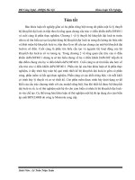
SITRANS P pressure transmitters, Z series (7MF1562 ), functional dia-
gram
The thin-film measuring cell has a thin-film resistance bridge at
which the operating pressure p is transmitted through a ceramic
diaphragm.
The measuring cell output voltage is fed to an amplifier and con-
verted into an output current of 4 to 20 mA. The output current
is linearly proportional to the input pressure.
p
I
0
, U
B
U
const.
U
I
SITRANS P measuring instruments for pressure
Transmitters for gage pressure
Z series for gage pressure
2/5
Siemens FI 01 · 2006
2
■
Technical specifications
■
Dimensional drawings
SITRANS P pressure transmitters, Z series (7MF1562 ), dimensions in
mm (inch)
■
Schematics
SITRANS P pressure transmitters, Z series (7MF1562 ), connection di-
agram
SITRANS P pressure transmitter, Z series for gage pressure
Mode of operation
Measuring principle Thin-film strain gage
Input
Measured variable Realtive pressure
Measured range 0 to 16 bar g (0 to 232 psi g) or
0 to 25 bar g (0 to 363 psi g)
Output
Current output signal 4 20 mA
Measuring accuracy To EN 60770-1
Error in measurement (at 25 °C
(77 °F), including conformity error,
hysteresis and repeatability)
0.5% of full-scale value - typical
Response time T
99
< 0.1 s
Long-term drift
• Start of scale 0.3% of full-scale value/year - typ-
ical
• Measured span 0.3% of full-scale value/year - typ-
ical
Influence of ambient temperature
• Start of scale 0.3%/10 K (0.3%/10 K) of full-
scale value - typical
• Measured span 0.3%/10 K (0.3%/10 K) of full-
scale value - typical
Rated conditions
Medium conditions
• Process temperature -30 +120 °C (-22 +248 °F)
Degree of protection to EN 60529 IP65
Ambient conditions
• Ambient temperature -25 85 °C (-13 +185 °F)
• Storage temperature -50 100 °C (-58 +212 °F)
Design
Weight ≈ 0.2 kg (≈ 0.44 lb)
Wetted parts materials
• Measuring cell Al
2
O
3
- 96%
• Process connection Brass, mat. No. 2.0402
• Gasket Viton
Process connection Male thread G½B
female thread G
1
/
8
B
Power supply
Terminal voltage on pressure trans-
mitter
• For current output 10 to 36 V DC
Certificate and approvals
Classification according to pressure
equipment directive
(DRGL 97/23/EC)
For gases of fluid group 1 and liq-
uids of fluid 1; complies with
requirements of article 3, para-
graph 3 (sound engineering prac-
tice)
6:
G
/
8
B
*%
0[
ෘ
GLDP
1+
2-
+
Signal
R
L
U
B
I
0
I
0
Output current
U
B
Power supply
R
L
Load
Connections:
1 (+U
B
)
2 (-U
B
)
■
Selection and Ordering data Order No. Order Code
SITRANS P pressure transmitters, Z series for pressure
2-wire system, characteristic rising
7 M F 1 5 6 2 -
777
0 0
Measured range Max. working pressure
0 16 bar g (0 232 psi g) 32 bar g (464 psi g) 3CB
0 25 bar g (0 363 psi g) 64 bar g (928 psi g) 3CD
Other version for measuring range ≥ 1 bar g (≥ 14.5 psi g), add Order Code and plain text:
Measuring range: to bar g (psi g)
9AA H 1 Y
Modification 02/2006
SITRANS P measuring instruments for pressure
Transmitters for gage and absolute pressure
Z series for gage and absolute pressure
2/6
Siemens FI 01 · 2006
2
■
Overview
SITRANS P pressure transmitters, Z series for pressure and absolute
pressure (7MF1564 )
SITRANS P pressure transmitters, Z series (7MF1564 ), mea-
sure the gage and absolute pressure as well as the level of liq-
uids and gases.
■
Benefits
• High measuring accuracy
• Sturdy stainless steel housing
• For aggressive and non-aggressive media
• For measuring the pressure of liquids, gases and vapor
• Temperature-compensated measuring cell
• Compact design
■
Application
The pressure transmitter of the Z series for gage pressure and
absolute pressure (7MF1564 ) is used above all in the follow-
ing industrial areas:
• Chemical industry
• Pharmaceutical industry
• Food industry
• Mechanical engineering
• Shipbuilding
• Water supply
■
Design
The design of the pressure transmitter is dependent on the mea-
suring range.
Measuring range <1 bar (<14.5 psi)
Main components:
• Stainless steel housing with piezo-resistive silicon measuring
cell (with stainless steel diaphragm, temperature-compen-
sated) and electronics module
• Process connection made of stainless steel in diverse designs
(see Selection and ordering data)
• Electrical connection made using a plug to DIN 43650 with the
cable inlet M16 x 1.5, ½-14 NPT or round plug connector M12.
The pressure transmitters with a nominal range < 1 bar g
(< 14.5 psi g) are optionally available with or without explosion
protection.
Measuring range
≥1 bar (≥14.5 psi)
Main components:
• Stainless steel housing with ceramic measuring cell and elec-
tronics module. The temperature-compensated ceramic mea-
suring cell has a thin-film strain gage which is mounted on a
ceramic diaphragm. The ceramic diaphragm can also be
used for aggressive media.
• Process connection made of stainless steel in diverse designs
(see Selection and ordering data)
• Electrical connection made using a plug to DIN 43650 with the
cable inlet M16 x 1.5, ½-14 NPT or round plug connector M12.
The pressure transmitters with a nominal range ≥ 1barg
(≥ 14.5 psi g) are optionally available with or without explosion
protection.
■
Function
The pressure transmitter measures the gage and absolute pres-
sure as well as the level of liquids and gases.
Mode of operation
SITRANS P pressure transmitters, Z series (7MF1564 ), functional dia-
gram
The mode of operation of the pressure transmitter is dependent
on the measuring range.
Measuring range <1 bar (<14.5 psi)
The silicon measuring cell of the pressure transmitter has a
piezo-resistive bridge to which the operating pressure is trans-
mitted through silicone oil and a stainless steel diaphragm.
The measuring cell output voltage is fed to an amplifier and con-
verted into an output current 4 20 mA. The output current is
linearly proportional to the input pressure
Measuring range
≥1 bar (≥14.5 psi)
The thin-film measuring cell has a thin-film resistance bridge to
which the operating pressure p is transmitted through a ceramic
diaphragm.
The voltage output from the measuring cell is converted by an
amplifier into an output current 4 20 mA or an output voltage
of 0 10 V DC.
The output current and voltage are linearly proportional to the in-
put pressure
p
I
0
, U
B
U
const.
U
I
SITRANS P measuring instruments for pressure
Transmitters for gage and absolute pressure
Z series for gage and absolute pressure
2/7
Siemens FI 01 · 2006
2
■
Technical specifications
■
Dimensional drawings
Pressure transmitter 7MF1564 with process connection G½" male, di-
mensions in mm (inch)
Pressure transmitter 7MF1564 with process connection G¼" male, di-
mensions in mm (inch)
SITRANS P pressure transmitters, Z series for gage pressure, abso-
lute pressure and level
Mode of operation
• Measuring range <1 bar
(<14.5 psi)
Piezo-resistive
• Measuring range ≥1bar
(≥14.5 psi)
Thin-film strain gage
Input
Measured variable Gage and absolute pressure
Measured range
• Pressure
- Metric 0 400 bar g (0 5802 psi g)
- US measuring range 0 6000 psi g
• Absolute pressure
- Metric 0 16 bar a (0 232 psi a)
- US measuring range 0 300 psi a
Output
Output signal
• Current output signal 4 20 mA
• Voltage output signal (only mea-
suring range ≥ 1 bar (14.5 psi))
0 10VDC
Accuracy To EN 60770-1
Error in measurement (at 25 °C
(77 °F), including conformity error,
hysteresis and repeatability)
0.25% of full-scale value – typical
Response time T
99
< 0.1 s
Long-term drift
• Start of scale 0.25% of full scale value/year
• Full-scale value 0.25% of full scale value/year
Influence of ambient temperature
• Start of scale 0.25%/10 K (0.25%/10 K) of full-
scale value
• Full-scale value 0.25%/10 K (0.25%/10 K) of full-
scale value
Rated operating conditions
Process temperature -30 °C +120 °C
(-22 … +248 °F)
Ambient temperature -25 °C +85 °C (-13 … +185 °F)
Storage temperature -50 °C +100 °C
(-58 … +212 °F)
Degree of protection to EN 60529 IP65
Design
Weight ≈ 0.25 kg (≈ 0.55 lb)
Wetted parts materials
• Measuring cell
- Measuring range <1 bar
(<14.5 psi)
Stainless steel, 1.4571/316Ti
- Measuring range ≥1bar
(≥14.5 psi)
Al
2
O
3
– 96%
• Process connection Stainless steel, mat. No.
1.4571/316Ti
• Gasket Viton
Process connection See Selection and ordering data
Power supply U
H
Terminal voltage on pressure trans-
mitter
• For current output 10 36 V DC
• For voltage output signal (only
measuring range ≥ 1bar
(14.5 psi))
15 36 V DC
Certificate and approvals
Classification according to pressure
equipment directive
(DRGL 97/23/EC)
For gases of fluid group 1 and liq-
uids of fluid 1; complies with
requirements of article 3, para-
graph 3 (sound engineering prac-
tice)
Explosion protection
• Intrinsic safety "i" (only with current
output)
TÜV 02 ATEX 1953X
- Identification Ex II 1/2G EEx ia IIC T4
• Intrinsic safety "T.I.I.S." (only with
current output)
applied
Lloyds Register of Shipping Certificate No. 03/30003
ZLWKRXW([SURWHFWLRQ
*%
ZLWK([SURWHFWLRQ
GLDP
6:
0[
RU
137
1) Length on version for voltage
output 0 10 V: 106 (4.2)
ZLWKRXW([SURWHFWLRQ
*%
ZLWK([SURWHFWLRQ
GLDP
6:
0[
RU
137
1) Length on version for voltage
output 0 10 V: 96 (3.8)
Modification 02/2006
SITRANS P measuring instruments for pressure
Transmitters for gage and absolute pressure
Z series for gage and absolute pressure
2/8
Siemens FI 01 · 2006
2
Pressure transmitter 7MF1564 with process connection 7/16-20 UNF
male, dimensions in mm (inch)
Pressure transmitter 7MF1564 with process connection ¼"-18 NPT
male, dimensions in mm (inch)
Pressure transmitter 7MF1564 with process connection ¼"-18 NPT
female, dimensions in mm (inch)
Pressure transmitter 7MF1564 with process connection G1“ male,
flush-mounted, dimensions in mm (inch)
Pressure transmitter 7MF1564 with process connection ½"-14 NPT
male, dimensions in mm (inch)
Pressure transmitter 7MF1564 with process connection ½"-14 NPT
female, dimensions in mm (inch)
■
Schematics
SITRANS P pressure transmitters, Z series (7MF1564 ), connection
diagram, with current output (top) and voltage output (bottom)
ZLWKRXW([SURWHFWLRQ
81)
GLDP
6:
0[
RU
137
ZLWK([SURWHFWLRQ
1) Length on version for voltage
output 0 10 V: 97 (3.8)
ZLWKRXW([SURWHFWLRQ
137
ZLWK([SURWHFWLRQ
GLDP
6:
0[
RU
137
1) Length on version for voltage
output 0 10 V: 101 (4)
1) Length on version for voltage
output 0 10 V: 98 (3.9)
ZLWKRXW([SURWHFWLRQ
ZLWK([SURWHFWLRQ
GLDP
6:
0[
RU
137
137
ZLWKRXW([SURWHFWLRQ
*
ZLWK([SURWHFWLRQ
GLDP
6:
0[
RU
137
1) Length on version for voltage
output 0 10 V: 103 (4.1)
ZLWKRXW([SURWHFWLRQ
137
ZLWK([SURWHFWLRQ
GLDP
6:
0[
RU
137
1) Length on version for voltage
output 0 10 V: 100 (4)
ZLWKRXW([SURWHFWLRQ
137
ZLWK([SURWHFWLRQ
GLDP
6:
0[
RU
137
1) Length on version for voltage
output 0 10 V: 98 (3.9)
1+
2-
+
Signal
R
L
U
B
I
0
I
0
Output current
U
B
Power supply
R
L
Load
Connections:
1 (+U
B
)
2 (-U
B
)
1+
3+
+
Signal
2-
R
L
U
B
U
0
U
0
Output voltage
U
B
Power supply
R
L
Load
Connections:
1 (+U
B
)
2 (-U
B
)
3 (U
0
)
Modification 02/2006
SITRANS P measuring instruments for pressure
Transmitters for gage and absolute pressure
Z series for gage and absolute pressure
2/9
Siemens FI 01 · 2006
2
■
Selection and ordering data Order No. Order code
SITRANS P pressure transmitters for pressure, series Z for gage and absolute pressure
2 or 3-wire system, rising characteristic curve
C)
7 M F 1 5 6 4 -
77777
-
777
1
777
Measuring range perm. working pressure Burst pressure
Min. Max.
For gage pressure
0 100 mbar g (0 1.45 psi g) -0,6 bar g (-8.7 psi g) 0,6 bar g (8.7 psi g) 1 bar g (14.5 psi g)
} 3AA 0
0 160 mbar g (0 2.32 psi g) -0,6 bar g (-8.7 psi g) 0,6 bar g (8.7 psi g) 1 bar g (14.5 psi g)
} 3AB 0
0 250 mbar g (0 3.63 psi g) -1 bar g (-14.5 psi g) 1bar g (14.5 psi g) 1.7 bar g (25 psi g)
} 3AC 0
0 400 mbar g (0 5.80 psi g) -1 bar g (-14.5 psi g) 1bar g (14.5 psi g) 1.7 bar g (25 psi g)
} 3AD 0
0 600 mbar g (0 8.70 psi g) -1 bar g (-14.5 psi g) 3bar g (43.5 psi g) 5 bar g (72 psi g)
} 3AG 0
Other version for measuring range < 1 bar (< 14.5 psi g), add Order Code and plain text:
measuring range: up to mbar g (psi g)
1)
9AC 0 H 1 Y
0 1 bar g (0 14.5 psi g) -0,4 bar g (-5.8 psi g) 2bar g (30 psi g) 5 bar g (72 psi g)
} 3BA
0 1.6 bar g (0 23.2 psi g) -0,4 bar g (-5.8 psi g) 3,2 bar g (45 psi g) 5 bar g (72 psi g)
} 3BB
0 2.5 bar g (0 36.3 psi g) -0,8 bar g (-11.6 psi g) 5bar g (72 psi g) 12 bar g (175 psi g)
} 3BD
0 4 bar g (0 58.0 psi g) -0,8 bar g (-11.6 psi g) 8bar g (115 psi g) 12 bar g (175 psi g)
} 3BE
0 6 bar g (0 87.0 psi g) -1 bar g (-14.5 psi g) 12 bar g (175 psi g) 25 bar g (360 psi g)
} 3BG
0 10 bar g (0 145 psi g) -1 bar g (-14.5 psi g) 20 bar g (290 psi g) 50 bar g (725 psi g)
} 3CA
0 16 bar g (0 232 psi g) -1 bar g (-14.5 psi g) 32 bar g (460 psi g) 50 bar g (725 psi g)
} 3CB
0 25 bar g (0 363 psi g) -1 bar g (-14.5 psi g) 50 bar g (725 psi g) 120 bar g (1750 psi g)
} 3CD
0 40 bar g (0 580 psi g) -1 bar g (-14.5 psi g) 80 bar g (1150 psi g) 120 bar g (1750 psi g)
} 3CE
0 60 bar g (0 870 psi g) -1 bar g (-14.5 psi g) 120 bar g (1750 psi g) 250 bar g (3600 psi g)
} 3CG
0 100 bar g (0 1450 psi g) -1 bar g (-14.5 psi g) 200 bar g (2900 psi g) 450 bar g (6525 psi g)
} 3DA
0 160 bar g (0 2320 psi g) -1 bar g (-14.5 psi g) 320 bar g (4640 psi g) 450 bar g (6525 psi g)
} 3DB
0 250 bar g (0 3626 psi g) -1 bar g (-14.5 psi g) 500 bar g (7250 psi g) 650 bar g (9425 psi g)
} 3DD
0 400 bar g (0 5802 psi g) -1 bar g (-14.5 psi g) 600 bar g (8700 psi g) 650 bar g (9425 psi g)
} 3DE
Other version for measuring range ≥ 1 bar g (≥ 14.5 psi g), add Order Code and plain text:
measuring range: up to bar (psi g)
1)
9AA H 1 Y
For absolute pressure
0 600 mbar a (0 8.7 psi a) 0bar a (0 psi a) 3bar a (43.5 psi a) 5bar a (72 psi a)
} 5AG 0
0 1 bar a (0 14.5 psi a) 0bar a (0 psi a) 2bar a (30 psi a) 5bar a (72 psi a)
} 5BA
0 1.6 bar a (0 23.2 psi a) 0bar a (0 psi a) 3,2 bar a (45 psi a) 5bar a (72 psi a)
} 5BB
0 2.5 bar a (0 36.3 psi a) 0bar a (0 psi a) 5bar a (72 psi a) 12 bar a (175 psi a)
} 5BD
0 4 bar a (0 58.0 psi a) 0bar a (0 psi a) 8bar a (115 psi a) 12 bar a (175 psi a)
} 5BE
0 6 bar a (0 87.0 psi a) 0bar a (0 psi a) 12 bar a (175 psi a) 25 bar a (360 psi a)
} 5BG
0 10 bar a (0 145 psi) 0bar a (0 psi a) 20 bar a (290 psi a) 50 bar a (725 psi a)
} 5CA
0 16 bar a (0 232 psi) 0bar a (0 psi a) 32 bar a (460 psi a) 50 bar a (725 psi a)
} 5CB
Other version for measuring range < 1 bar (< 14.5 psi a), add Order Code and plain text:
measuring range: up to mbar a (psi a)
9AB 0 H 1 Y
Measuring ranges for gage pressure (only for US market)
(0 10 psi g) (-3 psi g) (20 psi g) (60 psi g)
4BA
(0 15 psi g) (-6 psi g) (30 psi g) (72 psi g)
4BB
(3 15 psi g) (-6 psi g) (30 psi g) (72 psi g)
4BC
(0 20 psi g) (-6 psi g) (40 psi g) (72 psi g)
4BD
(0 30 psi g) (-6 psi g) (60 psi g) (72 psi g)
4BE
(0 60 psi g) (-11.5 psi g) (120 psi g) (175 psi g)
4BF
(0 100 psi g) (-14.5 psi g) (200 psi g) (360 psi g)
4BG
(0 150 psi g) (-14.5 psi g) (300 psi g) (725 psi g)
4CA
(0 200 psi g) (-14.5 psi g) (400 psi g) (725 psi g)
4CB
(0 300 psi g) (-14.5 psi g) (600 psi g) (1750 psi g)
4CD
(0 500 psi g) (-14.5 psi g) (1000 psi g) (1750 psi g)
4CE
(0 750 psi g) (-14.5 psi g) (1500 psi g) (3600 psi g)
4CF
(0 1000 psi g) (-14.5 psi g) (2000 psi g) (3600 psi g)
4CG
(0 1500 psi g) (-14.5 psi g) (3000 psi g) (6525 psi g)
4DA
(0 2000 psi g) (-14.5 psi g) (4000 psi g) (6525 psi g)
4DB
(0 3000 psi g) (-14.5 psi g) (6000 psi g) (9425 psi g)
4DD
(0 5000 psi g) (-14.5 psi g) (8700 psi g) (9425 psi g)
4DE
(0 6000 psi g) (-14.5 psi g) (8700 psi g) (9425 psi g)
4DF
Other version, add Order Code and plain text: Measuring range: up to psi g 9BA H 1 Y
} Available ex stock C) Subject to export regulations AL: N, ECCN: EAR99.
1) The transmitters can also be ordered with special measuring ranges, e.g. transmitters with a 1-bar measuring cell (14.5 psi measuring cell):
-0.2 +0.8 bar g (-2.9 +11.6 psi g) or
-0.4 +0.6 bar g (-5.8 +8.7 psi g) or
SITRANS P measuring instruments for pressure
Transmitters for gage and absolute pressure
Z series for gage and absolute pressure
2/10
Siemens FI 01 · 2006
2
■
Selection and ordering data Order No. Order code
SITRANS P pressure transmitters for pressure, series Z for pressure and absolute pressure
2 or 3-wire system, rising characteristic curve
C)
7 M F 1 5 6 4 -
77777
-
777
1
777
Measuring range Perm. working pressure Burst pressure
min. max.
Measuring ranges for absolute pressure (only for US market)
(0 10 psi a) (0 psi a) (20 psi a) (60 psi a)
6AG
(0 15 psi a) (0 psi a) (30 psi a) (72 psi a)
6BA
(0 20 psi a) (0 psi a) (40 psi a) (72 psi a)
6BB
(0 30 psi a) (0 psi a) (60 psi a) (72 psi a)
6BD
(0 60 psi a) (0 psi a) (120 psi a) (175 psi a)
6BE
(0 100 psi a) (0 psi a) (200 psi a) (360 psi a)
6BG
(0 150 psi a) (0 psi a) (300 psi a) (725 psi a)
6CA
(0 200 psi a) (0 psi a) (400 psi a) (725 psi a)
6CB
(0 300 psi a) (0 psi a) (600 psi a) (1725 psi a)
6CC
Other version, add Order Code and plain text: Measuring range: up to psi a 9BB H 1 Y
Output signal
4 20 mA; 2-wire system; power supply 10 36 V DC } 0
0 10 V; 3-wire system; power supply 15 36 V DC } 1 0
Explosion protection
Without } 0
With explosion protection EEx ia IIC T4 } 1
With explosion protection "Intrinsic safety T.I.I.S." (available soon) 2
Electrical connection
Plug to DIN 43650, Form A, cable inlet M16 x 1.5 } 1
Round connector M12 (available soon) 2
Plug to DIN 43650, cable inlet ½-14 NPT 3
Special version (specify Order Code and plain text) 9 N 1 Y
Process connection
G½" male to EN 837-1 (½" BSP male) (standard for metric pressure ranges mbar, bar) } A
G½" male thread and G1/8" female thread B
G¼“ male to EN837-1 (¼“ BSP male) C
7/16"-20 UNF male D
¼"-18 NPT male (standard for pressure ranges psi) E
¼"-18 NPT female F
½"-14 NPT male G
½"-14 NPT female H
RC ½" male to JIS B 7505 K
G1" male, flush-mounted (Only for measuring ranges ≥ 1 bar g (14.5 psi g)) M
Special version (specify Order Code and plain text) Z P 1 Y
Sealing material between sensor and housing
Viton (standard) } A
Neoprene B
Perbunan C
Special version (specify Order Code and plain text) Z Q1 Y
Further designs
Manufacturer’s test certificate M to DIN 55340, Part 18 and ISO 8402 (calibration certificate),
add "-Z" to Order No. and Order Code.
C11
Oxygen version, oil and grease-free cleaning (only if the sealing material between sensor and housing is
Viton and only for measuring ranges ≥ 1 bar g (≥ 14.5 psi g)
and ≥ 1 bar a (≥ 14.5 psi a)
E10
Manufacturer’s test certificate M to DIN 55340, Part 18 and ISO 8402 (calibration certificate) supplied later,
specify factory no. of transmitter.
7MF1564-8CC11
} Available ex stock C) Subject to export regulations AL: N, ECCN: EAR99.
Modification 04/2006