membrane technology a practical guide to membrane technology and applications in food and bioprocessing
Bạn đang xem bản rút gọn của tài liệu. Xem và tải ngay bản đầy đủ của tài liệu tại đây (5.88 MB, 299 trang )
Membrane Technology
Membrane Technology
A Practical Guide to Membrane Technology
and Applications in Food and Bioprocessing
Edited by
Z.F. Cui and H.S. Muralidhara
AMSTERDAM • BOSTON • HEIDELBERG • LONDON • NEW YORK • OXFORD
PARIS • SAN DIEGO • SAN FRANCISCO • SINGAPORE • SYDNEY • TOKYO
Butterworth-Heinemann is an imprint of Elsevier
Butterworth-Heinemann is an imprint of Elsevier
The Boulevard, Langford Lane, Oxford OX5 1GB, UK
30 Corporate Drive, Suite 400, Burlington, MA 01803, USA
First edition 2010
Copyright © 2010 Elsevier Ltd. All rights reserved
No part of this publication may be reproduced or transmitted in any form or by any means,
electronic or mechanical, including photocopying, recording, or any information storage and
retrieval system, without permission in writing from the publisher. Details on how to seek
permission, further information about the publisher’s permissions policies and our arrangements
with organizations such as the Copyright Clearance Center and the Copyright Licensing Agency,
can be found at our website: www.elsevier.com/permissions.
The
book
and the individual contributions contained in it are protected under copyright by
the Publisher (other than as may be noted herein).
Notices
Knowledge and best practice in this field are constantly changing. As new research and
experience broaden our understanding, changes in research methods, professional practices,
or medical treatment may become necessary.
Practitioners and researchers must always rely on their own experience and knowledge in
evaluating and using any information, methods, compounds, or experiments described herein.
In using such information or methods they should be mindful of their own safety and the safety
of others, including parties for whom they have a professional responsibility.
To the fullest extent of the law, neither the Publisher nor the authors, contributors, or editors,
assume any liability for the injury and/or damage to persons or property as a matter of products
liability, negligence or otherwise, or from any use or operation of any methods, products,
instructions, or ideas contained in the material herein.
British Library Cataloguing-in-Publication Data
A catalogue record for this book is available from the British Library
Library of Congress Cataloging-in-Publication Data Control Number
A catalog record for this book is available from the Library of Congress
ISBN: 978-1-85617-632-3
For information on all Butterworth-Heinemann publications
visit our website at elsevierdirect.com
Typeset by MPS Limited, a Macmillan Company, Chennai, India
www.macmillansolutions.com
Printed and bound in the United States of America
10111213 10987654321
Preface
Separation and purification are key to many manufacturing processes in the food, bio-
processing and pharmaceutical industries. Furthermore, these processes are becoming
increasingly important for the growth of industries such as bioenergy, biotechnology
and nanotechnology. The multiple steps involved in separation/purification processing
often require substantial up-front capital and significant operating costs. Thus the effi-
ciency and productivity of separation technology can be critical to both the profitabil-
ity and sustainability of an enterprise.
Recent developments in membrane technology, especially the development of
novel membrane processes, are the most growing areas of process technology. There
are several excellent books published in the general areas of membrane science and
membrane technology, but there is minimal focus on the applications of membrane
technology in food and pharma areas, even though they have grown steadily during
the last two decades. For example, one of the major applications in the food industry
is the use of reverse osmosis membranes to extend the evaporation capacity and reduce
the overall energy costs, thus lowering the carbon footprint for the overall process.
The idea for this book, which focuses on the practical applications of membranes
in food and bioprocessing, came out of a North American Membrane Society (NAMS)
meeting in Chicago, Illinois, USA, in 2006, when both editors held a workshop on
“Fundamentals and Applications of Membrane Technology in Food/Bio-processing”.
With our combined experience in food technology and bioprocessing, we felt that a
book dedicated to the practical aspects and challenges of utilizing membranes effec-
tively in an industrial setting would be an extremely useful tool for any one in mem-
brane processing and practice. The idea gained even more momentum when Elsevier
conducted a market study and subsequently expressed its interest in publishing a book
on the topic.
In many ways editing this book has been a privilege and a unique experience.
Thanks firstly to our excellent contributors without whose support, this book would
not have materialized. It is most fitting that this technological work is published from
contributors around the globe and is founded on the spirit of free enquiry coupled
with hard work and imagination. It has indeed been a great pleasure to be in touch
with all contributors during the last 3 to 4 years. Thanks also for their patience and
understanding.
We would be utterly remiss if we did not acknowledge those people who have
provided us with the inspiration, motivation and never-ending encouragement
throughout the course of this work.
Dr Murali would like to acknowledge Mr Ronald Christenson, former Chief
Technology Officer, Cargill Inc; his wife Ponnamma; his children Shubha and
Shilesh, their spouses Chuck Harris and Nupur Parikh and his two lovely grandchil-
dren Reya and Azad; all his teachers and mentors during his entire career; and his
parents who would have been both excited and extremely proud to see this book
published.
xi
Dr Cui wishes to thank his wife, Dr Jing Yu, for her unreserved support over dec-
ades, his mother for her love, and his children, Jenny and Michael, for “keeping him
happy”. He would like to thank those who inspired and encouraged him to embark on
a career in the “membrane world”. Such a list would be long, and here just name a
few: Tony Fane, John Howell, Norman Li and Bill Eykamp.
In setting our goal of bringing this book to fruition, we kept in mind these words
from Robert Frost in The Road Not Taken:
“Two roads diverged in a wood and I-
I took the one less travelled by,
And that has made all the difference”
ZFC and HSM
xii Preface
About the Editors
Zhanfeng Cui is the Donald Pollock Professor of Chemical Engineering, University
of Oxford since the Chair was established in 2000. He is the founding Director of the
Oxford Centre for Tissue Engineering and Bioprocessing (OCTEB).
He was educated in China and got his BSc from Inner Mongolia University
of Technology (1982) and MSc (1984) and PhD (1987) from Dalian University of
Technology. After a postdoctoral experience in Strathclyde University in Scotland, he
joined Edinburgh University as a Lecturer in Chemical Engineering (1991). He then
held academic appointments at Oxford Engineering Science Department as University
Lecturer (1994À1998) and Reader (1999À2000). He was a Visiting Professor of
Georgia Institute of Technology, USA (1999), the Brown Intertec Visiting Professor
to University of Minnesota, USA (2004), and a Chang-Jiang Visiting Professor to
Dalian University of Technology, China (2005). He is a Chartered Engineer, a
Chartered Scientist, and a Fellow of the Institution of Chemical Engineers. In 2009
he was award a Doctor of Science (DSc) by Oxford University to recognise his
research achievement in membrane science and technology. Apart from membrane
research, he also works on tissue engineering and stem cell technologies, and biopro-
cessing. He published widely and is also the academic founder of Zyoxel Limited, an
Oxford University spin-off in 2009.
H.S. Muralidhara Ph.D is a Chemical Engineer. He retired from Cargill Inc. in
Minneapolis, USA in Oct 2009 as a Vice President, Manager Process Technology,
Corporate Plant Operation after 20 years of service. Prior to that he was a Research
Leader at Battelle Memorial Institute in Columbus, Ohio, USA for 10 years. He is
currently an industrial consultant.
He has over 30 years of industrial experience in separation purification process
technologies including application of membranes in food and bioprocessing. He is a
coinventor of 27 US patents and 15 patents pending. He has edited two books and
has served as a key note speaker in many major international conferences.
xiii
About the Contributors
Vicki Chen is the director of the UNESCO Centre for Membrane Science and
Technology at The University of New South Wales, Australia.
Jim Davies is a biochemical engineer with a PhD from UCL and is currently a
Principal Group Leader in Purification Development at Lonza Biologics UK.
R.W. Field is a Reader in Engineering Science at Oxford University and has many
years of experience in membrane technologies.
Val D. Frenkel, PhD, PE, DWRE, Director Membrane Technologies with Kennedy/
Jenks Consultants, is the company-wide leader for Membrane Technologies.
Dr. Frenkel formed and leads the firm’s Membrane Technology Group and has
25 years of experience in engineering, with expertise in water and wastewater
treatment, water reuse, and membrane technologies, including desalination.
Yu Jiang was awarded her DPhil in 2009 from Oxford University. Her DPhil thesis
was entitled “Emergency drinking water device based on gravity driven
ultrafiltration”.
Bassam Jirjis is a Principal Chemical Engineer at Cargill Inc., in Minneapolis,
Minnesota. He has more than 25 years of experience in the area of separation
technologies and food processing.
N.S. Krishna Kumar, PhD, is a Senior Chemical Engineer at Cargill Inc.,
Minneapolis, Minnesota, USA. His research interest is focused on application of
membranes in food, bioprocessing and water treatment. He is currently involved
with vegetable oil process development research work concentrated towards pro-
cess improvement.
Abhay R. Ladhe is a Research Chemical Engineer at Cargill Inc., Minneapolis,
Minnesota, USA. He graduated from University of Kentucky with a Ph.D. in
Chemical Engineering. His research interests include membrane functionalization
and membrane based separation. He is currently working in the area of
vegetable oil processing for process improvement and process development.
Hongyu Li is a Research Fellow in the UNESCO Centre for Membrane Science and
Technology, The University of New South Wales, Australia.
Frank Lipnizki, PhD, is currently with Alfa Laval – Business Centre Membranes
(previously Danish Separation Systems), Denmark. Since 2010 also Docent at the
University of Lund, Sweden. His main research interests are the integration and
optimization of membrane process for the food, biotech and process industry.
Jianquan Luo, MEng, Institute of Process Engineering, Chinese Academy of
Sciences. Mr Luo is an experienced engineer specializing in membrane applica-
tions in bioseparation and wastewater treatment.
xv
Susana Luque is a Full Professor in Chemical Engineering at the University of
Oviedo in Spain. Her main interests are in applied membrane research and mem-
brane-based hybrid processes.
Alan Merry has a PhD in Chemical Engineering. He has 30 years’ experience at
ITT-PCI Membranes Ltd, working with all aspects of membranes including mem-
brane development, applications and production.
Joseph Scimeca, PhD, currently holds the position of Director of Global Regulatory
Affairs, in the department of Corporate Food Safety and Regulatory Affairs, at
Cargill, Incorporated, where he has responsibility for ensuring that the company’s
food and feed products and processes are safe, including being protected against
intentional acts of adulteration and bioterrorism, and are compliant with the
appropriate food/feed regulations.
Martin Smith, also a Biochemical Engineer from UCL, is currently a Bio-Process
Consultant at eXmoor Pharma Concepts in the fields of Biopharmaceuticals and
Regenerative Medicine.
Yinhua Wan, DPhil, is a Professor of Biochemical Engineering at Institute of
Process Engineering, Chinese Academy of Sciences. He has published more than
80 papers in refereed journals and holds a number of patents in membrane separa-
tion technologies.
xvi About the Contributors
Chapter 1
Fundamentals of
Pressure-Driv en Membrane
Separation Processes
Z.F. Cui, Y. Jiang and R.W. Field
Department of Engineering Science, Oxford University, Oxford, UK
Table of Contents
1.1 Introduction
1.2 Processes
1.2.1 Process Classification
1.2.2 Definitions
1.3 Membranes
1.3.1 Membrane Structures
1.3.2 Membrane Materials
1.3.3 Membrane Modules
1.4 Operation
1.4.1 Concentration
Polarization
1.4.2 Membrane Fouling
1.5 Prediction and Enhancement
of Permeate Flux
1.5.1 Flux Prediction Models
1.5.2 Flux Enhancement and
Fouling Control
1.6 Summary
Further Readings
1.1 INTRODUCTION
Membrane processes are one of the fastest growing and fascinating fields in
separation technology. Even though membrane processes are a relatively
new type of separation technology, several membrane proce sses, particularly
pressure-driven membrane processes including reverse osmosis (RO), nano-
filtration (NF), ultrafiltration (UF), and microfiltration (MF), are already
applied on an industrial scale to food and bioproduct processing.
The conce pt of membrane processes is relatively simple but nevertheless
often unknown. Membranes (lat.: membrana 5 thin skin) might be described
as conventional filters (like a coffee filter) but with much finer mesh or much
smaller pores to enable the separation of tiny particles, even molecules! In
1
Membrane Technology. DOI: 10.1016/B978-1-85617-632-3.00001-X
© 2010 Elsevier Ltd. All rights reserved.
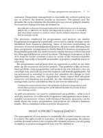
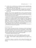
general, one can divide membranes into two groups: porous and nonporous.
The former group is similar to classical filtration with pressure as the dri ving
force; the separation of a mixture is achieved by the rejection of at least one
component by the membrane and passing of the other components through the
membrane (see Fig. 1.1).
However, it is important to note that nonporous
membr
anes
do not operate on a size exclusion mechanism. It should be
pointed out that this chapter focuses on pressure-driven membrane processes
using porous membranes for its close relevance to food and bioproduct
processing.
Membrane separation processes can be used for a wide range of applica-
tions
and
can
often offer significant advantages over conventional separation
such as distillation and adsorption since the separation is based on a physical
mechanism. Compared to conventional processes, therefore, no chemical,
biological, or thermal change of the component is involved for most mem-
brane processes. Hence membrane separation is particularly attractive to the
processing of food, beverage, and bioproducts where the processed products
can be sensitive to temperature (vs. distillation) and solvents (vs. extraction).
1.2 PROCESSES
1.2.1 Process Classification
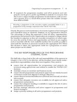
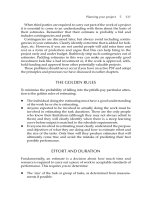
There are four major pressure-driven membrane processes that can be divided
by the pore sizes of membranes and the required transmembrane pressure
(TMP): MF (0.1À5 μm, 1À10 bar), UF (500À100,000 Da, 1À100 nm,
1À10 bar), NF (100À500 Da, 0.5À10 nm, 10À30 bar), and RO (,0.5 nm,
35À100 bar). Figure 1.2 pres
ents
a
classification on the applicability of differ-
ent membrane separation p rocesses based on particle or molecular sizes. RO
process is often used for desalination and pure water production, but it is the
UF and MF that are widely used in food and bioprocessing.
Mixture
A + B
Component A
Component B
Membrane
FIGURE 1.1 Basic principle of porous membrane processes. (Above is idealized; complete
separation is not achieved in practice.)
2 Membrane Technology
While MF membranes target on the microorganism removal, and hence
are given the absolute rating, namely, the diameter of the largest pore on the
membrane surface, UF/NF membr anes are characterized by the nominal rat-
ing due to their early applications of purifying biological solutions. The nom-
inal rating is defined as the molecular weight cut-off (MWCO) that is the
smallest molecular weight of species, of which the membrane has more than
90% rejection (see later for definitions). The separation mechanism in
MF/UF/NF is mainly the size exclusion, which is indicated in the nominal
ratings of the membranes. The other separation mechanism includes the elec-
trostatic interactions between solutes and membranes, which depends on the
surface and physiochemical properties of solutes and membranes.
1.2.2 Definitions
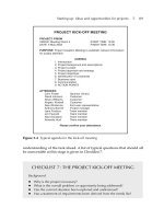
In contrast to Figure 1.1, real membrane separations split the feed mixture
stream into two streams with different compositions as shown in Figure 1.3.
The feed stream
_
m
F
to a membrane module is split into (i) the retentate
stream
_
m
R
, which is the stream that has been retained by the membrane
Feed Retentate
m
F
m
R
Permeate
m
P
FIGURE 1.3 A realistic membrane separation process.
0.001
Ionic
range
Macromolecular
range
Micron
particle
Fine
particle
Coarse
particle
µm 0.01 0.1 1.0 10 100 1000
Membrane process
Reverse
osomosis
Nano-
filtration
Ultrafiltration
Microfiltration Cloth, Fiber filter
Screens
FIGURE 1.2 The applicability ranges of different separation processes based on sizes.
3Chapter | 1 Fundamentals of Pressure-Driven Membrane Separation Processes
containing both the material that has been rejected by the membrane and a
quantity of material that would not be rejected by the membrane but has yet
not been given the opportunity to pass through the membrane; and (ii) the
permeate stream
_
m
P
, the stream that has passed through the membrane, con-
taining much less or no bigger molecules or particles than the pores.
Like any separation processes, the membrane separation processes can be
evaluated by two important parameters, efficiency and productivity. The pro-
ductivity is characterized by the parameter permeate flux, which indicates
the rate of mass transport across the membrane. In general terms, the local
mass transport of a component i through a membrane element is related to
its concentration on the feed side C
Ri
and the permeate side C
Pi
(see
Fig. 1.3). The flow of a component i through
a
membrane element can be
referred to as its flux J
i
. This flux is a velocity and is commonly expressed in
[kg/(m
2
s)] or [kmol/(m
2
s)]. When n components are permeating through the
membrane a total flux J
tot
can be defined as:
J
tot
5
X
n
i 5 1
J
i
ð1:1Þ
The retention factor R
i
of a component i can be defined and used as a
measure of performance.
R
i
5 1 2
C
P;i
C
R;i
ð1:2aÞ
where C
P
and C
R
are the concentration of component i in the permeate and
the retentate.
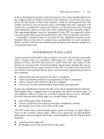
Actually pressure-driven membrane processes can be operated in two dif-
ferent modes: dead-end and cross-flow operations. In the dead-end mode, one
stream of the feed enters the membrane module and flows vertically toward
the membrane surface, and only one stream leaves the membrane module. In
the cross-flow mode, one stream of the feed flows tangentially to the mem-
brane surface, and there are two streams leaving the membrane module with
one for the retentate flow and the other for the permeate flow (as shown in
Fig. 1.3).
The dead-end mode is employed mostly in MF for clarification and
steri
lizatio
n, where the feed is relatively clean. In most applications, the accu-
mulation of the rejected particles or molecules is so severe that dead-end oper-
ation becomes impractical and cross-f low operation has to be adopted. The
tangential flow in the cross-flow mode can help to shear away the accumu-
lated rejected species at the membranes, limit the heights of cake layers, and
hence maintain the permeate flux. The schematic diagrams of the dead-end
mode and the cross-flow mode, and their effects on the permeate flux and the
height and resistance of the cake laye r, are shown in Figure 1.4.
In most applications dealing with aqueous solutions in food and biopro-
duct
p
rocessing,
the solvent permeate is largely water and permeate flux is
often conveniently presented as [m
3
/(m
2
s), i.e., m/s] or [L/(m
2
h), LMH],
4 Membrane Technology
which is the volume of m
p
produced per unit of membrane area per unit
time. Usually there is only one species, microparticle or macromolecule, to
be interested, and the rejection will only be referred to the concerned spe-
cies. Often the permeate flow rate is much less than the retentate flow rate in
a single pass, hence the change of concentration in the retentate is not signif-
icant. The rejection can then be conveniently calculated by:
R 5 1 2
C
P
C
F
ð1:2bÞ
where C
F
is the feed concentration.
The driving force in pressure-driven membrane separation is of course the
pressure, or the pressure difference between the upstream and the downstream
of the membrane, or between the feed and the permeate. This is referred to as
transmembrane pressure. As the pressure may vary in the membrane module
due to crossflow, an averaged pressure difference over the module is used:
TMP 5
ðP
F
2 P
P
Þ
in
1 ðP
F
2 P
P
Þ
out
2
ð1:3Þ
1.3 MEMBRANES
1.3.1 Membrane Structures
Porous membranes can be divided into two types according to their structures:
microporous membranes and asymmetric membranes. Microporous mem-
branes are characterized by the membrane pores throughout the membrane
Dead-end mode
Cross-flow mode
Feed
Retentate
Feed
R
C
R
M
Cake
Membrane
Permeate
Permeate
R
C
J
Time
R
C
J
Time
FIGURE 1.4 The schematic diagrams of the dead-end mode and the cross-flow mode, and their
effects on the permeate flux and the height of the cake layer (R À resistance as refereed later).
5Chapter | 1 Fundamentals of Pressure-Driven Membrane Separation Processes
bodies. The pores are of uniform size (isotropic) or nonuniform size (anisotro-
pic). Microporous membranes are designed to reject all the species above their
ratings. However, they tend to be blocked by the species that are of similar
sizes as the pores. The asymmetric membrane has a selective skin layer on the
top of its membrane body. The membrane body is usually void, only giving
mechanical support to the selective skin layer. Compared to the microporous
membranes, the asymmetric membranes rarely get blocked. Most UF, NF, and
RO membranes are of asymmetric structure, while most polymeric MF mem-
branes are of microporous structure.
1.3.2 Membrane Materials
In terms of materials, membranes can be classified into polymeric or organic
membranes and ceramic or inorganic membranes. Organic membranes are usu-
ally made up of various polymers, among which the typical ones are cellulose
acetate (CA), polyamide (PA), polysulfone (PS), polyethersulfone (PES), poly-
vinylidene fluoride (PVDF), polypropylene (PP), etc. Polymeric membranes are
relatively cheap, easy to manufacture, available in a wide range of pore sizes,
and they have been widely used in various industries. Nevertheless, most of the
polymeric membranes have limitations on one or more operating conditions
(either pH, or temperature, or pressure, or chlorine tolerance, etc.), which hinder
their wider applications. For example, CA is the classic material usually used to
produce the skinned membranes. However, it has many disadvantages such as
low temperature limit (30À40
C), narrow pH range (2À8, preferably 2À6),
and low chlorine tolerance (under 1 mg/L free chlorine).
Inorganic membranes have been commercialized since the early 1980s.
Due to their obvious advantages of high mechanical strength, and chemical
and thermal stability over the conventional polymeric membr anes, they have
extended the application of membrane technology into many new areas.
Inorganic membranes (such as γ-alumina/α-alumina, borosilicate glass, pyro-
lyzed carbon, zirconia/stainless steel, or zirconia/carbon) have strong toler-
ance to even extreme operating conditions. For instance, they have wide limits
of temperature, pH, and pressure, and have extended lifetime. However, inor-
ganic membranes are very brittle, so the membranes can be easily damaged by
dropping or unduly vibrating. Addit ionally the availability of such membranes
is only limited to mostly UF membranes and MF membranes today. In addi-
tion, cost is the biggest disadvantage in the applications of inorganic mem-
branes. They are far more expensive than polymeric membranes.
1.3.3 Membrane Modules
Membrane module is the way the membrane is arranged into devices and
hardware to separate the feed stream into permeate and retentate streams. So
far, there are four kinds of membrane modules that have been widely used in
6 Membrane Technology
industry. They are (1) tubular modules, (2) hollow fiber modules, (3) flat
sheet modules, and (4) spiral-wound modules. These membrane modules are
designed and developed by industry manufacturers in order to achieve differ-
ent characteristics on the hydrodynamic conditions, filtration areas, energy
consumptions, etc.
Tubular modules are composed of a number of membrane tubes assembled
in a shell-and-tube arrangement. The membrane tubes are usual ly made up of
porous fabric or plastic support with selective membranes on the inside. The
internal diameters of the tubes generally range from 5 to 25 mm, and the tube
lengths are in the range of 0.6 to 6 m. Tubular modules have some important
characteristics: (1) due to their large internal diamet ers, tubular modules are
capable of dealing with the feed stream containing fairly large particles.
Furthermore, they can be easily cleaned by using either mechanical or chemi-
cal cleaning methods; (2) they need large pumping capacity, because they are
usually operated under the turbulent flow conditions with the Reynolds num-
bers greater than 10,000; (3) they have the lowest surface area-to-volume ratio
among all the four membr ane configurations. The holdup volumes of tubular
modules are also high, which need large floor space to operate.
Hollow fiber modules are actually the “thin” tubular membranes in com-
pact modules, but in the form of self-support that enables them to withstand
high backpressure. Normally, hollow fiber modules are composed of
50À3000 individual hollow fibers, bundled and sealed together on each end
with epoxy in a hydraulically symmetric housing. The fiber diameters typi-
cally range from 0.2 to 3 mm (except those used in RO, which may be as
thin as 0.04 mm and can withstand much higher pressure). The fiber lengths
range from 18 to 120 cm. In MF and UF, hollow fiber modules are oper-
ated in the inside-out mode with selective skin layers on the inner sides of
the fibers , while in RO, they are operated in the outside-in mode with
selective skin layers on both sides of the fibers . Hollow fiber modules have
some very different characteristics from tubular modules: (1) they are
recommended to operate with the Reynolds numbers in the range of
500À3000, therefore, most of them are run in the laminar flow region.
Additionally, the pressure rating of hollow fiber modules is low, normally
with a maximum of 2.5 bar; (2) due to the combination of low cross flow
rate and low pressure drop, hollow fiber modules are one of the more eco-
nomical modules in terms of energy consumption; (3) hollow fiber modules
have the highest surface area-to-volume ratio amo ng all the four membrane
configurations, and their holdup volumes are low; (4) because the fibers are
self-supported, hollow fiber modules have good backwash capacity and are
hence easy to clean; and (5) one distinct disadvantage of hollow fiber mod-
ules is that, their thin fibers are susceptible to get blocked by the feed with
large particles, when they are operated in the inside-out mode. Therefore,
the pretreatment to reduce particle size to 100 μm is usual ly required for
hollow fiber modules.
7Chapter | 1 Fundamentals of Pressure-Driven Membrane Separation Processes
Flat sheet modules comprise a selective flat sheet membrane on the top
and a flat plate at the bottom, between which a net-like material is placed to
provide space for the permeate removal, and on the other side of the flat plate,
another sheet membrane and another net-like material are placed in mirror to
form a sandwich-like module. Flat sheet modules have channel gaps ranging
from 0.5 to 10 mm and are of lengths ranging from 10 to 60 cm. The superfi-
cial Reynolds numbers for flat sheet modules are in the laminar flow region;
however, good mixing can be achieved when a screen is placed in the feed
channel. The pretreatment to 150 μm is recommended for flat sheet modules.
With regard to packing density, energy consumption, and cost, flat sheet mod-
ules lie in between tubular modules and spiral-wound modules.
The design of spiral-wound modules is similar to that of flat sheet mod-
ules. In the spiral-wound modules, two membrane sheets are separated by a
mesh-like spacer with the active membrane sides facing away. Three edges
of the two membrane sheets are glued together with the fourth edge open
to a perforated center tube for the permeate removal. On the other two
sides of “the envelope,” another two mesh-like spacers with thicknesses in
the range of 0.56À3 mm are placed as the feed channel spacers. The whole
assembly is rolled around the perforated center tube in a spiral configura-
tion. The characteristics of spiral-wound modules are as follows: (1) spiral-
wound modules are operated in the turbulent flow region because of
the presence of feed spacers; (2) due to the addi tional drag generated by
feed spacers, the pressure drop in spiral-woun d modules is relatively high;
(3) spiral-wound modules have fairly high surface areaÀvolume ratio and
are the lowest in terms of capital cost, among all the four kinds of mem-
brane modules; and (4) suspended particles can easily block the mesh-like
spacers and then partially block the feed channel. Therefore, spiral-wound
modules require relatively clean feed that are with minimum content of sus-
pended particles. The pretreatment to reduce suspended particles is needed
for spiral-wound modules.
1.4 OPERATION
1.4.1 Concentration Polarization
Concentration polarization refers to the reversible accumulation of rejected
molecules close to the membrane surface. In membrane processes all compo-
nents in the feed are transported to the membrane surface by convection, and
the rate increases as the permeation through the membrane increas es. The
selectivity of the membrane holds back the less permeable components. At
steady state, these less permeable components have to be transported back
into the bulk of the feed stream. As the flow next to the membrane surface is
laminar, this transport can only be diffusive. The transport has to be based on
the established concentration gradient, i.e., an enrichment of the less
8 Membrane Technology
permeable components at membrane surface, as shown in Figure 1.5.Itisa
natural consequence of membrane selectivity and is equivalent to the mass
transfer boundary. If driving force is removed, permeation ceases, and such a
concentration polarization phenomenon disappears.
Under steady-state conditions, the following relationships describe the
relevan
t
flu
xes based on Figure 1.5:
Component 1
J
1;con
5 J
1
ð1:4Þ
Component 2
J
2;con
5 J
2;diff
1 J
2
ð1:5Þ
The following assumptions are made to obtain a mass balance on the
feed side of the membrane:
●
the process is steady state,
●
the diffusion is described by Frick’s law,
●
there is no chemical reaction,
●
the concentration gradient parallel to membrane can be neglected,
●
the density is constant, and
●
the coefficient is independent from the solute concentration.
Hence in general,
J
i
UC
i
5 J
i
UC
i;P
2 D
ji
dC
i
dz
ð1:6Þ
Membrane
J
1
J
2
J
1,con
J
2,con
C
1F
C
1F,M
J
2,diff
I
b
Z
Concentration boundary
layer
Bulk
feed
FIGURE 1.5 Concentration polarization.
9Chapter | 1 Fundamentals of Pressure-Driven Membrane Separation Processes
Integration of Equation (1.6) taking the following boundary conditions
into account,
z 5 0 C
i
5 C
i;M
z 5 l
b
C
i
5 C
i;b
yields
J
i
5
D
ji
l
b
Uln
C
i;M
2 C
i;P
C
i;b
2 C
i;P
ð1:7Þ
In Equation (1.7), the term (D
ji
/l
b
) can be described as a mass transfer
coefficient k
i,b
.
For one interested species to be rejected and the solvent to be just water,
Equation (1.7) can be rewritten as:
J 5 kUln
C
M
2 C
P
C
B
2 C
P
ð1:8Þ
and for a total rejection operation where C
P
5 0, we have
J 5 kUln
C
M
C
B
ð1:9Þ
According to Equation (1.9), a higher mass transfer coefficient, k, and
a
higher membrane surface concentration lead to a higher permeate flux.
Equation (1.9) help
s to explain the commonly observed UF behaviors as
show
n
in Figure 1.6. In the pressure control region, the increase in TMP
increases flux, leading to a higher C
M
. But if C
M
reaches a certain value of
Higher flow rate
Higher temperature
Lower concentration
Mass transfer
controlled region
Transmembrane pressure
Water
Pressure
controlled
region
Flux
FIGURE 1.6 The influences of operating parameters on permeate flux, showing the pressure
control region and the mass transfer control region.
10 Membrane Technology
macromolecule’s gelation concentration or the solubility of the rejected salt,
gelation or salt precipitation occurs and C
M
reaches its maximum value.
Further increase in TMP does not have any effect on C
M
, and hence the flux,
J, does not change 2 a region known as pressure-independent region.
On the other hand, increase in the mass transfer coefficient, k, by
increas-
ing
cross-flow velocity leads to a higher permeate flux, as indicated in
Equation (1.9).
The mass transfer coefficient can be estimated on the basis of heat and
mas
s
transfer
analogy (so-called Colburn analogy) using the semiempirical
Sherwood correlation. This correlation can be written as:
Sh 5 aURe
b
USc
c
U
d
l
d
ð1:10Þ
The adjustment of the variables a, b, c, d in Equation (1.10) is
based on
the
flow
regime and the module (see Tables 1.1 and 1.2).
TABLE 1.1 Variables a, b, c, d for the Sherwood Correlation,
Equation (1.10)
Flow regime abcdSystem
Laminar
1
1.62 0.33 0.33 0.33 Hollow fiber
Turbulent
2
0.04 0.75 0.33 À Tubular
Laminar
3
1.615 0.33 0.33 0.33 Flat sheet
Turbulent
4
0.026 0.8 0.3 À Flat sheet, tubular
1
Re , 2100 hydrodynamic fully developed profile, not fully developed concentration boundary
layer.
2
Re , 10,000.
3
Re , 2300 hydrodynamic fully developed profile, not fully developed concentration boundary
layer.
4
Re . 2300.
TABLE 1.2 Dimensionless Numbers
Reynolds number: Re 5
ρud
h
μ
Sherwood number: Sh 5
kUd
h
D
Schmidt number: Sc 5
μ
DUρ
5
ν
D
Hydraulic diameter:
For tubes d
h
5 d
tube
For noncircular channel d
h
5 4
Cross-section area
Wetted perimeter
d
h
, equivalent hydraulic diameter; D, diffusivity of the rejected species; ρ, density of the feed
solution; μ, viscosity of the feed solution; ν, kinematic viscosity of the feed solution.
11Chapter | 1 Fundamentals of Pressure-Driven Membrane Separation Processes
1.4.2 Membrane Fouling
Fouling is generally defined as a process resulting in a loss of performance
of a membrane due to deposition of suspended or dissolved substances onto
its external surface. Fouling cannot be removed simply by stopping the filtra-
tion process. Fouling is often the main limit ation to the successful membrane
application of food and biotech industries.
Fouling can be seen as a reduction in the active area of the membrane
and leads therefore to a reduction in flux belo w theoretical capacity of the
membrane. Several parameters influence the fouling rate such as:
●
nature and concentration of solutes and solvents,
●
membrane type,
●
pore size distribut ion,
●
surface characteristics and material of membranes, and
●
hydrodynamics of membrane module.
Fouling can be related to different modes such as adsor ption, chemical
interactions, cake formation, and pore blocking by particles. These modes
can lead to blockage or partial blockage of the active membrane area or to
deposition of a layer onto the membrane surface. In Table 1.3,
examples of
foulants
in membrane processes are given.
TABLE 1.3 Examples of Foulants and Fouling Modes in Membrane
Processes
Foulants Fouling mode
Large suspended
particles
Particles present in the original feed or developed in the process
by scaling can block module channels.
Small colloidal
particles
Colloidal particles can rise to a fouling layer. Fouling of
membranes in recovery of cells from fermentation broth.
Macromolecules Gel or cake formation on membrane. Macromolecular fouling
within the structure of porous membranes.
Small molecules Some small organic molecules tend to have strong interactions
with plastic membranes (e.g., antifoaming agents such as
polypropylene glycols used during fermentation foul certain plastic
ultrafiltration membranes).
Proteins Interactions with surface or pores of membranes.
Chemical
reactions
Concentration increase and pH increase can lead to precipitation
of salts and hydroxides.
Biological Growth of bacteria on the membrane surface and excretion of
extracellular polymers.
12 Membrane Technology
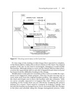
Generally speaking, four fouling mechanisms for porous membranes can
be observed, as shown in Figure 1.7:
(a) complete pore blocking,
(b) intern
al
pore blocking,
(c) partial pore blocking, and
(d) cake filtrati on.
The following differential equation can be used to describe the influence
of fouling on the flux through the membrane in the absence of any cross-
flow effect
J 5 J
0
U½1 1 KUð2 2 nÞðAUJ
0
Þ
ðn 2 2Þ
Ut
ð2 2 nÞ
ð1:11Þ
In this equation, the phenomenological coefficients n and K depend on
the fouling mechanism. In Table 1.4, the different values of n,
their
phenom-
enological background, their effect on the mass transport, and the relevant
transport equations are given.
1.5 PREDICTION AND ENHANCEMENT OF PERMEATE FLUX
1.5.1 Flux Prediction Models
Numerous different models have been developed to p redict the permeate flux
as a function of operating parameters, membrane properties, and feed proper-
ties in UF. However, due to the limitations of application conditions and
model assumptions, or not enough under standing of the phenomena that take
place around the membrane surface, no model so far is universally applicable
or fully satisfactory. Nevertheless, these models can help to understand the
operation and performance links.
The pore model is appl ied to predict the permeate flux in the pressure
control region, under the conditions of no fouling and negligible concentra-
tion polarization. In this model, it can be assumed that (1) membrane pores
(A) Complete pore blocking (B) Internal pore blocking
(C) Partial pore blocking (D) Cake filtration
FIGURE 1.7 Fouling mechanisms of porous membranes.
13Chapter | 1 Fundamentals of Pressure-Driven Membrane Separation Processes
TABLE 1.4 Fouling Mechanisms, Phenomenological Background, Effect on Mass Transport, and Transport Equations
Fouling Mechanism n Phenomenological
Background
Effect on Mass Transport Transport Equation
Complete pore
blocking (see
Fig. 1.7a)
2 Particles
larger than the pore
size; the active membrane area
(pores) reached by particles is
blocked.
Reduction of the active
membrane area. Depending on
feed velocity, permeate might
be increased by increasing
transmembrane driving force
(pressure).
J 5 J
0
UK
b
AUt ð1:12Þ
Internal pore blocking
(see Fig. 1.7b)
1.5 Part
icles
smaller than pore size
enter the pores and get either
adsorbed or deposited in the
pore. Reduction in pore volume
leads to blinding of pores.
Increase in membrane
resistance due to pore size
reduction. Internal pore
blocking is independent from
feed velocity. No limiting might
be observed, J
min
5 0.
J 5 J
0
U 1 1
1
2
UK
s
UðAUJ
0
Þ
0:5
Ut
2 2
ð1:13Þ
Particle pore blocking
(see Fig. 1.7c)
1 An
y
particles reaching a pore
might seal it over time. Particles
might bridge a pore and not
block it completely.
Reduction of active membrane
area. The effect is similar to
pore blocking but not so severe.
J 5 J
0
U½1 1 K
i
UðAUJ
0
ÞUt
2 1
ð1:14Þ
Cake filtration (see
Fig. 1.7d)
0 Forma
ti
on of a cake on the
membrane surface of particles
that do not enter the pores.
The overall resistance becomes
the resistance of the membrane
plus the resistance of the cake.
J 5 J
0
U½1 1 2UK
c
UðAUJ
0
Þ
2
Ut
2 1=2
ð1:15Þ
14 Membrane Technology
are ideal cylindrical channels and are uniformly distributed on the membrane
surface; (2) the permeate passing through membrane pores are laminar flow
in the steady state; and (3) the applied feed is of constant density (e.g.,
incompressible) and Newtonian (with no dependence on the shear rate). The
permeate flu x can be calculated using the HagenÀPoiseuille equation, which
is based on the momentum balance:
J
v
5
n
p
d
4
p
ΔP
128μl
p
ð1:16Þ
where J
v
is the permea te flux, n
p
the number of cylindrical pores per unit
area, d
p
the pore diameter, ΔP the TMP, l
p
the pore length, and μ the viscos-
ity of the permeate.
The equation shows that the permeate flux is directly proportional to the
TMP and inversely proportional to the viscosity. The viscosity is primarily
controlled by the solvent type, feed composition, and temperature. Therefore,
in the pressure control region, increasing the temperature and pressure, and
decreasing the feed concentration can increase the permeate flux.
The resistance model is developed to express the entire TMP-flux behav-
ior in MF and UF, both in the pressure control region and in the mass trans-
fer control region. This model is based on the resistance-in-series concept,
which is a common concept in heat transfer. With the ideal membrane and
the ideal feed that lead to no fouling, the model can be expre ssed as:
J
v
5
ΔP
μR
m
ð1:17Þ
where J
v
is the permeate flux, ΔP the TMP, μ the viscosity of the permeate,
and R
m
the hydraulic resistance of the membrane, which is a constant value for
each membrane and can be determined by measuring the pure water flux.
By consideration of the effect of concentration polarization, the increase
in solute concentrations near the membrane surface results in the increase in
osmosis pressure, which effectively reduces the TMP. The permeate flux is
then calculated by:
J
v
5
ΔP 2 Δπ
μR
m
ð1:18Þ
where Δπ is the osmosis pressure difference between the solution at mem-
brane surface and the permeate. Noting Δπ is dependent on C
M
, Equation
(1.18) can be used in conjunction with Equations (1.9)
and
(1.10) to calculate
permeate flux in UF and NF if the osmotic pressure dependence on solute
concentration is given.
In the filtration of real feeds, both concentration polarization and mem-
brane
fouling
occur
to add additional resistances to the membrane and hence
to the permeate to pass through. Therefore, the resistance of the polarized
15Chapter | 1 Fundamentals of Pressure-Driven Membrane Separation Processes