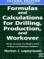
formulas and calculations for drilling production and workover 2e
Bạn đang xem bản rút gọn của tài liệu. Xem và tải ngay bản đầy đủ của tài liệu tại đây (15.04 MB, 234 trang )
-54
SECOND EDITION
with
NEW
&
UPDATED MATERIAL
11
L
Formulas
Calculations
for Drilling,
Production,
Workover
and
and
Second
Edition Formulas
and
Calculations
for
Drilling,
Production,
and
Workover
Second
Edition
Norton
J.
Lapeyrouse
Gulf
Professional
Publishing
an
imprint
of
Elsevier
Science
Amsterdam
Boston London New
York Oxford Paris
San Diego
San Francisco Singapore
Sydney Tokyo
Gulf Professional Publishing is an imprint
of
Elsevier Science.
Copyright
0
2002,
Elsevier Science (USA). All rights reserved
No
part
of
this publication may be reproduced, stored in a retrieval
system, or transmitted in any form or by any means, electronic,
mechanical, photocopying, recording, or otherwise, without the prior
written permission
of
the publisher.
Recognizing the importance of preserving what has been written,
@
Elsevier-Science prints its books on acid-free paper whenever possible.
Library
of
Congress Cataloging-in-Publication Data
Lapeyrouse, Norton
J.
Formulas and calculations for drilling, production, and workover
1
Norton
J.
Lapeyrouse 2nd ed.
p. cm.
Includes index.
1. Oil wells-Management-Mathematics.
I.
Title.
ISBN
0-7506-7452-0
TN871 .L287 2002
622’.3382 dc2
1
2002074579
British Library Cataloguing-in-Publication Data
A catalogue record for this book
is
available from the British Library.
The publisher offers special discounts on bulk orders
of
this book.
For information, please contact:
Manager of Special Sales
Elsevier Science
200
Wheeler
Road
Burlington, MA
01803
Tel:
78 1-3 13-4700
Fax:
781-221-1615
For information on all Gulf publications available, contact our World
Wide Web home page at:
1098 765432
Printed in the United States of America
CONTENTS
PREFACE
vii
1
BASIC FORMULAS
.1
Pressure Gradient
1.
Hydrostatic Pressure 3. Converting Pressure into
Mud Weight 4. Specific Gravity
5.
Equivalent Circulating Density
6.
Maximum Allowable Mud Weight 7. Pump Output 7. Annular
Velocity 9. Capacity Formulas 12. Control Drilling 19. Buoyancy
Factor
20.
Hydrostatic Pressure Decrease When Pulling Pipe out
of
the Hole 20.
Loss
of Overbalance Due to Falling Mud Level 22.
Formation Temperature
24.
Hydraulic Horsepower 25. Drill Pipe/Drill
Collar Calculations 25. Pump Pressure/Pump Stroke Relationship 27.
Cost per Foot
28.
Temperature Conversion Formulas 29.
2
BASIC CALCULATIONS
.31
Volumes and Strokes 3
1.
Slug Calculations
33.
Accumulator
Capacity 37. Bulk Density
of
Cuttings 41. Drill String Design
(Limitations) 42. Ton-Mile Calculations
44.
Cementing Calculations 47.
Weighted Cement Calculations 53. Calculations for the Number
of
Sacks
of
Cement Required
54.
Calculations for the Number
of
Feet to
Be Cemented
57.
Setting
a
Balanced Cement Plug 61. Differential
Hydrostatic Pressure Between Cement in the Annulus and Mud Inside
the Casing 65. Hydraulicing Casing 66. Depth
of
a Washout
70.
Lost
Returns-Loss
of
Overbalance 7
1.
Stuck Pipe Calculations 72.
Calculations Required for Spotting Pills 75. Pressure Required to
Break Circulation 79.
V
3
DRILLING FLUIDS
81
Increase Mud Density 81. Dilution
85.
Mixing Fluids
of
Different
Densities 86. Oil-Based Mud Calculations 87. Solids Analysis 91. Solids
Fractions 95. Dilution
of
Mud System 96. Displacement-Barrels
of
Water/Slurry Required 97. Evaluation
of
Hydrocyclone 97. Evaluation
of
Centrifuge 99.
4
PRESSURE CONTROL
.
.
.
.
.
.
.
.
.
.
.
.
.
.
.
.
.
. .
. .
. .
.
. .
.
.
.
. .
.
. .
.
.lo3
Kill Sheets and Related Calculations 103. Prerecorded
Information 115. Kick Analysis 124. Pressure Analysis 137.
Stripping/Snubbing Calculations 139. Subsea Considerations 144.
Workover Operations 153. Controlling Gas Migration 157. Gas
Lubrication 159. Annular Stripping Procedures 161.
5
ENGINEERING CALCULATIONS
.
.
.
.
.
.
.
.
. . .
.
.
. . .
.
. .
.
.
.
.
.
.
.165
Bit Nozzle Selection-Optimized Hydraulics 165. Hydraulics
Analysis 169. Critical Annular Velocity and Critical Flow Rate 173.
“d”
Exponent 174. Cuttings Slip Velocity 175. Surge and Swab
Pressures 179. Equivalent Circulation Density 187. Fracture Gradient
Determination-Surface Application 190. Fracture Gradient
Determination-Subsea Application
194.
Directional Drilling
Calculations 197. Miscellaneous Equations and Calculations 203.
APPENDIXA
209
APPENDIX
B
217
INDEX
221
vi
PREFACE
Over the last several years, hundreds of oilfield personnel have told me that
they have enjoyed this book. Some use it as a secondary reference source:
others use it as their primary source for formulas and calculations; still others
use it
to
reduce the volume of materials they must carry to the rig floor or
job site.
Regardless of the reason people use it, the primary purpose
of
the book
is to provide
a
convenient source of reference to those people who don’t use
formulas and calculations on a regular basis.
In the preface to the first edition,
I
made reference to a driller who carried
a briefcase full of books with him each time he went to the rig floor.
I
also
mentioned a drilling supervisor who carried two briefcases
of
books. This
book should reduce the number of books each of them needs to perform
his job.
This book is still intended to serve oilfield workers for the entirety
of
their
careers. I have added several formulas and calculations, some in English field
units and some in Metric units.
I
have also added the Volumetric Procedure,
the Lubricate and Bleed Procedure (both Volume and Pressure Method), and
stripping procedures (both the Strip and Bleed Procedure and the Combined
Stripping and Volumetric Procedure).
This book has been designed for convenience.
It
will occupy very little
space in anyone’s briefcase. It has a spiral binding
so
it will lay flat and stay
open on
a
desk. The Table
of
Contents and the Index make looking up for-
mulas and calculations quick and easy. Examples are used throughout to
make the formulas as easy as possible to understand and work, and often
exact words are used rather than symbols.
This book is dedicated to the thousands of oilfield hands worldwide who
have
to
use formulas and calculations, whether on a daily basis or once or
twice a year, and who have problems remembering them. This book should
make their jobs
a
little easier.
vii
ONE
BASIC
FORMULAS
Pressure Gradient
~
Pressure gradient, psilft, using mud weight, ppg
pdft
=
mud weight, ppg
x
0.052
Example:
12.Oppg fluid
psi/ft
=
12.Oppg
x
0.052
psilft
=
0.624
Pressure gradient, psi/ft, using mud weight, lblfl?
pdft
=
mud weight, lb/ft3
x
0.006944
Example:
100 lb/ft3 fluid
psi/ft
=
lOOlb/ft'
x
0.006944
pdft
=
0.6944
OR
pdft
=
mud weight, Ib/ft3
+
144
Example:
100
lb/ft3 fluid
psi/ft
=
10O1b/ft3
+
144
pdft
=
0.6944
Pressure gradient, psi/ft, using mud weight, specific gravity
(SG)
pdft
=
mud weight,
SG
x
0.433
E-xample:
I
.O
SG
fluid
pdft
=
1.OSG
x
0.433
pdft
=
0.433
2
Formulas and Calculations
Metric calculations
Pressure gradient, barlm
=
drilling fluid density
kg/l
x
0.0981
Pressure gradient,bar/lOm
=
drilling fluid density
kg4
x
0.981
S.I.
units calculations
Pressure gradient, kPa/m
=
drilling fluid density,
kg/m3
t
102
Convert pressure gradient, psilft, to mud weight, ppg
ppg
=
pressure gradient, psdft
+
0.052
Example:
0.4992 psi/ft
ppg
=
0.4992psilft
+
0.052
ppg
=
9.6
Convert pressure gradient, psilft, to mud weight, Ib/ft3
lb/ft3
=
pressure gradient, psdft
+
0.006944
Example:
0.6944 pdft
lb/ft3
=
0.6944psilft
+
0.006944
Ib/ft3
=
100
Convert pressure gradient, psilft, to mud weight,
SG
SG
=
pressure gradient,
pdft
+
0.433
Example:
0.433 pdft
SG
=
0.433pdft
+
0.433
SG
=
1.0
Metric calculations
Drilling fluid density,
kg/l
=
pressure gradient, badm
Drilling fluid density,
kg/l
=
pressure gradient, bar/l0m
+
0.981
0.0981
Basic Formulas
3
S.I.
units calculations
Drilling fluid density. kg/m3
=
pressure gradient, kPa/m
x
102
Hydrostatic Pressure (HP)
-
-_
Hydrostatic pressure using ppg and feet as the units
of
measure
HP
=
mud weight, ppg
x
0.052
x
true vertical depth (TVD), ft
Example:
mud weight
=
13.5ppg
true vertical depth
=
12,OOOft
HP
=
13.5ppg
x
0.052
x
12,OOOft
HP
=
8424psi
Hydrostatic pressure, psi, using pressure gradient, psilft
HP
=
psi/ft
x
true vertical depth, ft
Example:
pressure gradient
HP
=
0.624pdft
x
8500ft
HP
=
5304psi
=
0.624 psi/ft
true vertical depth
=
8500ft
Hydrostatic pressure, psi, using mud weight, lb/f@
HP
=
mud weight, lb/ft3
x
0.006944
x
TVD, ft
Example:
mud weight
=
90lb/ft'
true vertical depth
=
7500ft
HP
=
901b/ft3
x
0.006944
x
7500ft
HP
=
4687psi
Hydrostatic pressure,
psi,
using meters as unit of depth
HP
=
mud weight, ppg
x
0.052
x
TVD, m
x
3.281
Example:
mud weight
=
12.2ppg
true vertical depth
=
3700 meters
4
Formulas
and
Calculations
HP
=
12.2ppg
x
0.052
x
3700
x
3.281
HP
=
7701psi
Metric calculations
Hydrostatic
-
drilling fluid true vertical
pressure, bar density, kg/l
0'0981 depth,
m
-
S.I.
units calculations
Hydrostatic
-
drilling fluid density,
kg/m3
-
x
true vertical depth,
m
pressure, kPa 102
Converting Pressure into
Mud
Weight
Convert pressure, psi, into mud weight, ppg, using feet as
the unit of measure
Mud weight, ppg
=
pressure, psi
+
0.052
+
TVD,
ft
Example:
pressure
=
26OOpsi
true vertical depth
=
5OOOft
Mud,
ppg
=
26OOpsi
+
0.052
+
5OOOft
Mud
=
1O.Oppg
Convert pressure, psi, into mud weight, ppg, using meters
as
the unit
of
measure
Mud weight, ppg
=
pressure, psi
+-
0.052
+
TVD,
m
+
3.281
Example:
pressure
=
3583psi
Mud wt, ppg
=
3583psi
+
0.052
+
2000m
+
3.281
Mud wt
=
10.5ppg
true vertical depth
=
2000
meters
Basic Formulas
5
Metric calculations
true vertical
+
0.0981
-+
Equivalent drilling
-
pressure,
fluid density,
kgfl
bar depth, m
-
S.I.
units calculations
true vertical
depth, m
x
102
+
Equivalent drilling
-
pressure,
fluid density, kglm'
-
kPa
~
-
Specific
_-
Gravity (SG)
___
-
~
Specific gravity using mud weight, ppg
SG
=
mud weight, ppg
+
8.33
Example:
15.Oppg fluid
SG
=
15.Oppg
+
8.33
SG
=
1.8
Specific gravity using pressure gradient, psilft
SG
=
pressure gradient, psi/ft
+
0.433
Example:
pressure gradient
=
0.624pdft
SG
=
0.624psUft
+
0.433
SG
=
1.44
Specific gravity using mud weight, lb/ft3
SG
=
mud weight, Ib/ft'
+
62.4
Example:
mud weight
=
1201b/ft3
SG
=
1.92
SG
=
1201b~t3
+
62.4
6
Formulas and Calculations
Convert specific gravity to mud weight, ppg
Mud weight, ppg
=
specific gravity
x
8.33
Example:
specific gravity
=
1.80
Mud wt, ppg
=
1.80
x
8.33
Mud wt
=
15.Oppg
Convert specific gravity to pressure gradient, psilft
psi/ft
=
specific gravity
x
0.433
Example:
specific gravity
=
1.44
psi/ft
=
1.44
x
0.433
pdft
=
0.624
Convert specific gravity to mud weight, lblft?
lb/ft3
=
specific gravity
x
62.4
Example:
specific gravity
=
1.92
Ib/ft3
=
1.92
x
62.4
lb/ft3
=
120
Equivalent Circulating Density (ECD), ppg
i
0.052
i
TVD, ft
+
Example:
annular pressure
loss
=
2OOpsi
true vertical depth
=
10,OOOft
mud weight
=
9.6ppg
ECD, ppg
=
2OOpsi
+
0.052
+
10,OOOft
+
9.6ppg
ECD
=
1o.oppg
Basic
Formulas
I
Metric calculation
+
0.0981
+
TVD, m
+
mud
wt,
kg/l
Equivalent drilling
-
annular pressure
fluid density, kg/l
loss,
bar
-
S.I.
units calculations
Equivalent circulating
-
annular pressure
loss,
kPa
x
102
density,
kg/l
TVD.
m
-
+
mud density, kg/m
Maximum Allowable
Mud Weight from Leak-off Test Data
casing shoe
I
+
(rp;d weight,)
TVD, ft
+
0.052
+
leak-off
pressure, psi
PPg
=
(
Example: leak-off test pressure
=
1140psi
casing shoe TVD
=
4000ft
mud weight
=
1o.oppg
ppg
=
114Opsi
+
0.052
+
4000ft
+
1O.Oppg
ppg
=
15.48
~~~~ ~
Pump Output (PO)
Triplex Pump
Formula
1
PO,
bbl/stk
=
0.000243
x
(:Eieter, in.y
x
(;:E:;,
in)
E.xample: Determine the pump output, bbllstk, at 100% efficiency for a
7-in. by 12-in. triplex pump:
PO
@
loo'%,
=
0.000243
x
7'
x
12
PO
@
100%
=
0.142884bbVstk
Adjust the pump output for
95%
efficiency:
8
Formulas and Calculations
Decimal equivalent
=
95
+
100
=
0.95
PO
@
95%
=
0.142884bbVstk
x
0.95
PO
@
95%
=
0.13574bbllstk
Formula
2
PO,
gpm
=
[3(D2
x
0.7854)S]0.00411
x
SPM
where D
=
liner diameter, in.
S
=
stroke length, in.
SPM
=
strokes per minute
Example:
Determine the pump output, gpm, for a 7-in. by 12-in. triplex
pump at
80 strokes per minute:
PO,
gprn
=
[3
(72
x
0.7854)
121 0.0041
1
x
80
PO,
gpm
=
1385.4456
x
0.0041
1
x
80
PO
=
455.5gpm
Duplex
Pump
Formula
1
0.000324
x
(!EAeter,
in.)3
x
(;:$E,
in)
=
bbl/stk
pump output
@
100% eff
=
bbllstk
Example:
Determine the output, bbllstk, of a 5-112in. by 14-in. duplex
pump at 100% efficiency.
Rod
diameter
=
2.0in.:
0.000324
x
5.S2
x
14
=
0.137214bbVstk
-0.000162
x
2.02
x
14
=
0.009072bbVstk
Pump output
@
100%
eff
=
0.128142bbVstk
Adjust pump output for
85%
efficiency:
Decimal equivalent
=
85
+
100
=
0.85
Basic
Formulas
9
PO
@
85%)
=
0.128 142 bbYstk
x
0.85
PO@
85%
=
0.10892bbVstk
Formula
2
PO.
bbVstk
=
0.000162
x
S[2(D)?
-
d']
where
S
=
stroke length, in.
D
=
liner diameter, in.
d
=
rod diameter, in.
Example:
Determine the output, bbl/stk,
of
a 5-1/2-in. by 14-in. duplex
pump
@
100%) efficiency. Rod diameter
=
2.0in.:
PO
@
100%
=
0.000162
x
14
x
[2
(5.5)'
-
2'1
PO
@
100%)
=
0.000162
x
14
x
56.5
PO@
100%)
=
0.128142bbVstk
Adjust pump output for
85%
efficiency:
PO@
85'%,
=
0.128142bbYstk
x
0.85
PO
@
8.504)
=
0.10892bbVstk
Metric calculation
Pump output, literlmin
=
pump
output. literlstk
x
pump speed, spm
S.I.
units calculation
Pump output, m'/min
=
pump output, liter/stk
x
pumpspeed, spm
Annular velocity (AV), ftlmin
Formula
I
AV
=
pump
output, bbVmin
+
annular capacity. bbVft
10
Formulas and Calculations
Example:
pump output
=
12.6 bbl/min
annular capacity
=
0.1261 bbl/ft
AV
=
12.6bbVmin
+
0.1261bbVft
AV
=
99.92ftlmin
Formula
2
24.5
x
Q
AV,
ft/min
=
Dh2
-
Dp2
where
Q
=
circulation rate, gpm
Dh
=
inside diameter
of
casing or
hole
size, in.
Dp
=
outside diameter of pipe, tubing or collars, in.
Example:
pump output
=
530gpm
hole size
=
12-1/4in.
pipe OD
=
4-1/2in.
24.5
x
530
AV
=
12.252
-
4.52
12,985
129.81
25
AV
=
~
AV
=
100ftlmin
Formula
3
PO,
bbVmin
x
1029.4
AV,
ft/min
=
Dh2
-
Dp2
Example:
pump output
=
12.6bbllmin
hole size
=
12-1/4in.
pipe
OD
=
4-1/2in.
12.6bbVmin
x
1029.4
12.252
-
4.5*
AV
=
12970.44
129.8 125
AV
=
-
AV
=
99.92ftlmin
Basic
Formulas
11
Annular velocity
(AV),
ftlsec
17.16
x
PO, bbVmin
Dh?
-
Dp2
AV, ft/sec
=
Example:
pump output
=
12.6bbUmin
hole size
=
12-1/4in.
pipe OD
=
4-1/2111,
17.16
x
12.6bbVmin
AV
=
12.25'
-
4.5'
216.216
129.8125
AV
=
AV
=
1.6656 ft/sec
Metric calculations
Annular velocity, dmin
=
pump output, literhnin
+
annular volume, lhn
Annular velocity, dsec
=
pump output, liter/min
+
60
+
annular volume,
lhn
S.I.
units calculations
Annular velocity. dmin
=
pump output, m'/min
+
annular volume,
m3/m
Pump output, gpm, required for a desired annular velocity, ftlmin
AV, ft/min(Dh'
-
DP')
24.5
Pump output, gpm
=
where
AV
=
desired annular velocity, ft/min
Dh
=
inside diameter
of
casing or hole size, in.
Dp
=
outside diameter
of
pipe, tubing or collars.
in
E.xample:
desired annular velocity
=
120
ft/min
hole size
=
12-1/4in.
pipe
OD
=
4-112in.
120(12.252
-
4.52)
24.5
PO
=
12
Formulas
and
Calculations
120
x
129.8125
24.5
Po=
1
5,577.5
PO
=
____
24.5
PO
=
635.8gpm
Strokes per minute
(SPM)
required for a given annular velocity
annular ve!ocity, ft/min
x
annular capacity, bbllft
pump output, bbVstk
SPM
=
Example:
annular velocity
=
120ft/min
annular capacity
=
0.1261
bbl/ft
Dh
=
12-1/4in.
DP
=
4-1/2in.
pump output
=
0.136 bbllstk
120ft/min
x
0.1261bbVft
0.136 bbllstk
SPM
=
15.132
0.136
SPM
=
___
SPM
=
111.3
Capacity Formulas
Annular capacity between casing or hole and drill pipe, tubing,
or
casing
Dh2
-
Dp2
1029.4
a) Annular capacity, bbYft
=
Example:
Hole size (Dh)
=
12-1/4in.
Drill pipe
OD
(Dp)
=
5.0in.
12.252
-
5.02
1029.4
Annular capacity, bbVft
=
Annular capacity
=
0.12149bbYft
Basic
Formulas
13
1029.4
b) Annular capacity, ft/bbl
=
(Dh2
-
Dp2)
Example:
Hole size
(Dh)
=
12-1/4in.
Drill pipe
OD
(Dp)
=
5.0in.
1029.4
Annular capacity, ft/bbl
=
(12.252
-
5.02)
Annular capacity
=
8.23fthbl
Dh2
-
Dp’
c)
Annular capacity, gaVft
=
24.51
Example:
Hole size
(Dh)
=
12-1/4in.
Drill pipe OD (Dp)
=
5.0in.
12.252
-
5.02
24.51
Annular capacity, gaVft
=
Annular capacity
=
5.lgaYft
24.51
(Dh2
-
Dp2)
d)
Annular capacity, ft/gal
=
Example:
Hole size
(Dh)
=
12-1/4in.
Drill pipe OD (Dp)
=
5.0in.
24.5
1
Annular capacity, ft/gal
=
(12.25*
-
5.02)
Annular capacity
=
0.19598ftlgal
DhZ
-
Dp2
183.35
e)
Annular capacity, ft3/linft
=
Example:
Hole
size (Dh)
=
12-1/4in.
Drill pipe
OD
(Dp)
=
5.0in.
12.25*
-
5.02
Annular capacity, ft3/linft
=
183.35
Annular capacity
=
0.682097ft3/linft
14
Formulas
and Calculations
f) Annular capacity, linft/ft3
=
Examule:
Hole size (Dh)
183.35
(Dh2
-
Dp2)
=
12-1/4in.
Drill pipe OD’(Dp)
=
5.0in.
183.35
Annular capacity, linft/ft3
=
(12.252
-
5.02)
Annular capacity
=
1.466 linft/ft
Annular capacity between casing and multiple strings
of
tubing
a) Annular capacity between casing and multiple strings
of
tubing, bbl/ft:
Dh2
-
+
(T2)2]
Annular capacity, bbYft
=
1029.4
Example:
Using two strings of tubing of same size:
Dh
=
casing-7.0in 29lb/ft ID
=
6.184in.
TI
=
tubing
No.
1-2-3/8in. OD
=
2.375in.
T2
=
tubing
No.
2-2-3/8in. OD
=
2.375in.
6.1842
-
(2.3752
+
2.3752)
Annular capacity, bbVft
=
1029.4
38.24
-
11.28
Annular capacity, bbVft
=
1029.4
Annular capacity
=
0.02619bbYft
b)
Annular
capacity between casing
and
multiple
strings
of
tubing, ft/bbl:
1029.4
Annular capacity, ft/bbl
=
Dh2
-
[UJ2
+
(T’)*]
Example:
Using two strings of tubing of same size:
Dh
=
casing-7.0in 29lb/ft
ID
=
6.184in.
TI
=
tubing
No.
1-2-3/8in.
OD
=
2.375in.
T2
=
tubing
No.
2-2-3/8in. OD
=
2.375in.
1029.4
Annular capacity, ft/bbl
=
6.184’
-
(2.3752
+
2.375’)
Busic
Forinulas
15
1029.4
Annular capacity, ft/bbl
=
38.24
-
11.28
Annular capacity
=
38.1816ftlbbl
c) Annular capacity between casing and multiple strings of tubing,
gal/ft:
Dh2
-
[(T,)’
+
(T?)’]
24.5
1
Annular capacity, gaVft
=
Example:
Using two tubing strings of different size:
Dh
=
casing-7.0in 29 lb/ft
ID
=
6.184in.
TI
=
tubing
No.
1-2-3/8in.
OD
=
2.375in.
T2
=
tubing
No.
2-3-112in.
OD
=
3Sin.
6.1842
-
(2.375’
+
3.5’)
24.5
1
Annular capacity, gaVft
=
38.24
-
17.89
Annular capacity, gaVft
=
24.5
1
Annular capacity
=
0.8302733gaVft
d) Annular capacity between casing and multiple strings of tubing.
ft/gal:
34.51
Annular capacity, ft/gal
=
Dh2
-
[(T,)’
+
(T?)’]
Example;
Using two tubing strings of different sizes:
Dh
=
casing-7.0in 29lb/ft
ID
=
6.184in.
T,
=
tubing
No.
1-2-3/8in.
OD
=
2.375in.
T2
=
tubing
No.
2-3-1/2in.
OD
=
3.5in.
24.51
6.184’
-
(2.3752
+
3.5’)
Annular capacity, ft/gal
=
24.5
1
Annular capacity, ft/gal
=
38.24
-
17.89
Annular capacity
=
1,2044226 fuga1
16
Formulas and Calculations
e) Annular capacity between casing and multiple strings of tubing, ft3/linft:
Dh2
-
[VJ2
+
(T2I2]
Annular capacity, ft3/linft
=
183.35
Example:
Using three strings
of
tubing:
Dh
=
casing-9-98 in.47 lb/ft
ID
=
8.681in.
TI
=
tubing
No.
1-3-1/2in. OD
=
3.5in.
T2
=
tubing
No.
2-3-1/2in.
OD
=
3.5in.
T3
=
tubing
No.
3-3-1/2in.
OD
=
3.5in.
-
8.6812
-
(3S2
+
3S2
+
3S2)
Annular capacity
-
183.35
183.35
Annular capacity, ft3/linft
=
75.359
-
36.75
Annular capacity
=
0.2105795ft3/linft
f)
Annular capacity between casing and multiple strings of tubing, linft/ft3:
183.35
Annular capacity, linft/ft3
=
Dh2
-
[(T,12
+
(T212]
Example:
Using three strings tubing of same size:
Dh
=
casing-9-5/8 in.47lblft
ID
=
8.681in.
TI
=
tubing
No.
1-3-1/2in.
OD
=
3.5in.
TI
=
tubing
No.
2-3-1/2in. OD
=
3.5in.
T,
=
tubing
No.
3-3-1/2in.
OD
=
3.5in.
Annular capacity
-
183.35
-
8.6812
-
(3.52
+
3.52
+
3.52)
183.35
Annular capacity, linft/ft3
=
75.359
-
36.75
Annular capacity
=
4.7487993 linft/ft3
Capacity
of
tubulars and open hole: drill pipe, drill collars, tubing,
casing, hole, and any cylindrical object
ID,
in?
a)
Capacity, bbVft
=
~
1029.4


