pipeline rules of thumb handbook, 7th edition
Bạn đang xem bản rút gọn của tài liệu. Xem và tải ngay bản đầy đủ của tài liệu tại đây (13.54 MB, 763 trang )
Gulf Professional Publishing is an imprint of Elsevier.
30 Corporate Drive, Suite 400, Burli ngton, MA 01803, USA
Linacre House, Jordan Hill, Oxford OX2 8DP, UK
Copyright ß 2009 by Elsevier Inc. All rights reserved.
No part of this publication may be reproduced, stored in a retrieval system, or
transmitted in any form or by any me ans, electronic, mechanical, photocopying,
recording, or otherwise, without the prior written permission of the publisher.
Permissions may be sought directly from Elsevier’s Science & Technology
Rights Department in Oxford, UK: (þ44) 1865 843830, fax: (þ44) 1865 853333,
e-mail: You may also complete your request on-line via the
Elsevier Science homepage (), by selecting ‘‘Customer Support’’
and then ‘‘Obtaining Permissions.’’
Recognizing the importance of preserving what has been written, Elsevier prints its
books on acid-free paper whenever possible.
Library of Congress Cataloging-in-Publication Data
Application submitted
British Library Catalo guing-in-Publication Data
A catalogue record for this book is avai lable from the British Library.
ISBN: 978-1-85617-500-5
For information on all Gulf Professional Publishing publications
Visit our Web site at www.books.elsevier.com
09 10 11 12 13 5 4 3 2 1
Printed in the United States of America
Contents
1: General Information, 1
Basic formulas 2
Mathematics—areas 3
Mathematics—surfaces and volumes 4
Rules of exponents 5
Recommended drill sizes for self-tapping screws 5
Determine pulley speed 5
Calculate volume in horizontal storage tank with
ellipsoidal or hemispherical heads 6
ASTM standard reinforcing bars 7
Pressure rating for carbon steel flanges 7
Cables and Ropes 8
Estimating strength of cable 8
Find the working strength of Man ila rope 8
How large should drums and sheaves be for various
types of wire rope? 8
Find advantages of block and tackle, taking into
account pull out friction 9
Safe loads for wire rope 9
Stress in guy wires 10
Strength and weight of popular wire rope 12
Measuring the diameter of wire rope 12
Wire rope: field troubles and their causes 12
Capacity of drums 14
Belts and Shafts 14
Determine length of a V-belt 14
Calculate stress in shaft key 15
Calculate V-belt length using simple equation 15
Estimate the horsepower that can be
transmitted by a shaft 16
Miscellaneous 16
How to estimate length of material contained
in roll 16
Convenient antifreeze chart for winterizing
cooling systems 16
How to determine glycol requirements to bring a
system to a desired temperature protection level 17
Weight in pound s of round steel shafting 17
Properties of shafting 18
Tap drills and clearance drills for machine screws 19
Common nails 20
Drill sizes for pipe taps 20
Carbon steel—color and approximate temperature 20
Bolting dimensions for flanges 21
Steel fitting dimensions 22
ANSI forged steel flanges 23
Trench shoring—minimum requirements 24
Reuniting separated me rcury in thermometers 25
v
Typical wire resistance 25
How to cut odd-angle long radius elbows 26
How to read land descriptions 27
Sample sections showing rectangular land descriptions,
acreages, and distances 28
Size an air receiver for engine starting 29
Dimensions of hex nuts and hex jam nuts 30
Color codes for locating underground utilities 31
Approximate angle of repose for sloping
sides of excavations 31
Wind chill chart 32
Pipeline Pigging 33
Sizing plates 33
Caliper pigging 33
Cleaning after construction 33
Flooding for hydrotest 34
Dewatering and drying 34
Estimate volume of onshore oil spill 34
Estimating spill volume on water 36
Fluid Power Formulas 37
2: Construction, 39
Project Scoping Data 40
Project scoping data worksheet for major
facilities 40
Right-of-Way 42
How to determine the crop acreage included in a
right-of-way strip 42
Clearing and grading right-of-way: labor/equipment
considerations 43
Estimating manhours for removing trees 43
Estimating manhours for removing tree stumps 44
Clearing and grading right-of-way 44
Ditching 45
How many cubic yards of excavation in a
mile of ditch?. 45
Shrinkage and expansion of excavated and
compacted soil. 45
Ditching and trenching: labor/equipment
considerations 45
Concrete Work 46
How to approximate sacks of ce ment
needed to fill a form 46
What you should know about mixing and
finishing concrete 46
Pipe Laying 47
How to determine the degrees of bend in a pipe
that must fit a ditch calling for a bend in both
horizontal and vertical planes 47
How to bend pipe to fit ditch—sags, overbends, and
combination bends 47
Pipe bending computations made with
hand-held calculator 48
Calculate maximum bend on cold pipe 52
Determine length of a pipe bend 53
Length of pipe in arc subtended by any angle 53
Average pipelay table—underground 54
Average pipelay table—on supports 55
Allowable pipe span between supports 55
How engineers make pipe fit the ditch. 56
Pipe Lowering 59
How to lower an existing pipeline tha t is still
in service 59
Welding 62
When should steel be preheated before
welding? 62
Welding and brazing temperatures 63
Mechanical properties of pipe welding rods 63
Lens shade selector 64
Pipeline Welding 64
How many welds will the average welder make
per hour? 73
How much welding rod is required for a mile
of schedule 40 pipeline? 73
How many pounds of electrodes are required
per weld on line pipe?. 73
Welding criteria permit safe and effective
pipeline repair. 74
Cross country pipeline—vertical down electrode
consumption, pounds of electrode per joint 80
Guidelines for a successful directional crossing
bid package 81
3: Pipe Design, 89
Steel pipe design 90
Properties of pipe 95
Length of pipe in bends 98
Calculation of pipe bends 99
Spacing of pipe supports 101
American standard taper pipe threads (NPT) 103
British standard taper pipe threads 104
vi Contents
Normal engagement between male and female
threads to make tight joints 105
Hand-held computer calc ulates pipe weight,
contents, velocity 105
Formulas and constants of value in solving problems
relating to tubular goods 108
How to calculate the contract ion or expansion
of a pipeline 109
Estimate weight of pipe in metric tons per kilometer 109
How to find pipe weight from outside diameter and
wall thickness 110
What is the maximum allowable length of
unsupported line pipe? 110
Identify the schedule numbe r of pipe by direct
measurement 110
Determine buoyancy of bare steel pipe 111
Determine buoyancy of bare and concrete-coated
steel pipe in water and mud 111
Weights of piping materials 112
Allowable working pressure for carbon steel pipe 112
Find the stress in pipe wall due to internal pressure 113
How to calculate stress in aboveground/belowground
transitions 114
How to identify the series number of flanged fittings 117
Dimensions of three-diameter ells with tangents 117
Spectacle blind thicknesses 117
Polypipe design data 118
4: Electrical Design, 121
Electrical design 122
Hazardous locations 123
NEMA enclosure types 124
Size portable electric generators 125
Typical wattages for tools and appliances 126
Knockout dimensions 126
National Electrical Code tables 127
Electrical formulas 131
Full load currents—single phase transformers 131
Conduit size for combinations of cables with
different outside diameters 132
Minimum bending radius for insulated cables for
permanent training during installation 132
Full load currents—three phase transformers 134
Motor controller sizes 134
Voltage drop on circuits using 600 V copper
conductors in steel conduit 135
Determine the most economica l size for
electric power conductors 135
How to find the resistance and weight of
copper wires 136
What you should remember about electrical
formulas 136
How to calculate microwave hops on level ground 136
For quick determination of the horsepower per
ampere for induction motors (3 phase) at
different voltages 137
Chart of electric motor horsepower for
pumping units 137
Pumping stations 138
Floodlighting Concepts 139
Terms 139
Floodlighting calculations 139
Point-by-point metho d 139
Beam-lumen method 140
Design procedure 140
Conductor size conversion chart—Metric to AWG 141
Commonly used switchgear device numbers 142
Bonding the grounding system to building and
structure foundations 143
5: Hydrostatic Testing, 145
The Benefits and Limitations of
Hydrostatic Testing 146
Hydrostatic testing for pipelines 157
Appendix A 163
Volume of water required to fill test section 163
Volume require d at test pressure 164
Appendix B 165
How to use charts for estimating the amount
of pressure change for a change in test
water temperature 165
Basis for chart development 168
Compressibility factor for water 168
Hydrostatic test records 168
6: Pipeline Drying, 169
Pipeline Dewatering, Cleaning,
and Drying 170
Dewatering 170
Cleaning pipelines 171
Brush pig run with gas 171
Brush pig run with liquid 171
Internal sand blasting 171
Contents vii
Chemical cleaning 172
Pipeline drying 172
Moisture content of air 174
Commissioning petrochemical pipelines 176
Vacuum drying 179
7: Control Valves, 183
Control valve sizing formulas 184
Sizing control valves for throughput 188
Control valve selection 193
Relief Valve Sizing, Selection,
Installation, and Testing 195
Rupture disc sizing 199
Rupture disc sizing using the resistance to
flow method (K
R
) 200
Variable orifice rotary control valves 202
Sizing Valves for Gas and Vapor 204
Basic valve flow-capacity coefficient (C
V
) 204
Visualize pump and control valve interaction
easily 208
Avoid cavitation in butterfly values 214
8: Corrosion/Coatings, 219
Hand-held computer determines concrete
coating thickness 220
National Association of Pipe Coating Applications
(NAPCA) specifications 222
How much primer for a mile of pipe? 225
How much coal-tar enamel for a mile of pipe? 226
How much wrapping for a mile of pipe? 226
Estimating coating and wrapping materials required
per mile of pipe 226
Coefficient of friction for pipe coating
materials 227
Troubleshooting cathodic protection systems:
Magnesium anode system 229
Cathodic protection for pipelines 230
Estimate the pounds of sacrificial anode material
required for offshore pipelines 238
Comparison of other reference electrode potentials
with that of copper–copper sulfate reference
electrode at 25
C 240
Chart aids in calculating ground bed resistance
and rectifier power cost 241
How can output of magnesium anodes be
predicted? 242
How to determine the efficiency of a cathodic
protection rectifier 242
How to calculate the voltage drop in ground
bed cable quickly 243
What is the most economical size for a rectifier
cable? 243
How to estimate the number of magn esium
anodes required and their spacing for a bare
line or for a corrosion ‘‘hot spot’’ 244
How can resistivity of fresh water be
determined from chemical analysis? 244
What will be the resistance to earth of a
single graphite anode? 245
How to estimate the monthly power bill for a
cathodic protection rectifier 245
What will be the resistance to earth of a group of
graphite anodes, in terms of the resistance
of a single anode? 245
How can the current output of magnesium rod
used for the cathodic protection of heat exchanger
shells be predicted? 245
What spacing for test leads to measure current
on a pipeline? 245
How many magnesium anodes are needed for
supplementary protection to a short-circuited
bare casing? 246
Group installation of sacrificial anodes 246
How can the life of magnesium anodes be
predicted? 247
How to find the voltage rating of a rectifier if
it is to deliver a given amount of current through
a given ground bed (graphite or carbon) 247
Determining current requirements for coated lines 247
Determining current requirements for coated lines
when pipe-to-soil potential values are
estimated 247
HVDC effects on pipelines 248
Troubleshooting cathodic protection systems:
Rectifier-groun d bed 252
How to control corrosion at compre ssor stations 253
Project leak growth 254
Advances in Pipeline Protection 255
Methods of locating coating defects 256
Case histories 259
Estimate the number of squares of tape for
pipe coating (machine applied) 260
Estimate the amount of primer required for tape 261
Tape requirements for fittings 261
Induced AC Voltages on Pipelines
May Present a Serious Hazard 262
viii Contents
Measuring Unwanted Alternating
Current in Pipe 264
Minimizing shock hazards on pipelines
near HVAC lines 269
Cathodic protection test point installations 270
Corrosion of Low-Velocity, High Water
Cut Oil Emulsion Pipelines 271
Internal Stray Current Interference
Form an External Current Source 275
9: Gas—General, 281
Know the gas laws 282
Calculate gas properties from a gas analysis 284
Physical properties of selected hydrocarbons and
other chemicals and gases 288
Nomograph for calculating density and specific
volume of gases and vapors 296
Considerations for Selecting Energy
Measurement Equipment 297
Facts about methane and its behavior 303
Conversion table for pure methane 307
Categories of natural gas and reserv es terminology 308
Glossary of common gas industry terms 309
10: Gas—Compression, 313
Compressors 314
Performance calculations for reciprocating
compressors 315
Estimate suction and discharge volume bottle
sizes for pulsation control for reciprocating
compressors 317
Compression horsepower determination 319
Generalized compressibility factor 321
Nomograph aids in diagnosing compressor cylinder ills. 322
Centrifugal Compressor Data 323
Centrifugal compressor performance calculations 323
Nomographs for estimating compressor performance 327
Estimate hp required to compress natural gas 332
Estimate compressor hp where di scharge pressure
is 1,000 psi 332
Calculate brake horsepower required to
compress gas 333
How to find the size of a fuel gas line for a
compressor station 333
Estimate engine cooling water requirements 334
Estimate fuel requirements for internal
combustion engines 334
Estimate fuel requirements for compressor
installation 335
Performance testing guidelines for centrifugal
compressors 335
11: Gas—Hydraulics, 347
Gas pipeline hydraulics calculations 348
Equivalent lengths for multiple lines based on
Panhandle A 349
Determine pressure loss for a low-pressure
gas system 350
Nomograph for determining pipe-equivalent
factors 351
How much gas is contained in a given line section? 352
How to estimate equivalent length factors for
gas lines 352
Estimating comparative capacities of gas pipelines 353
Determination of leakage from gas line using
pressure drop method 353
A quick way to determine the size of gas gathering
lines 354
Energy conversion data for estimating 354
How to estimate time required to get a shut-in test
on gas transmission lines and approximate a
maximum acceptable pressure loss for new lines 355
How to determine the relationship of capacity
increase to investment increase 355
Estimate pipe size requirements for increasing
throughput volumes of natural gas 356
Calculate line loss using cross-sectional areas table
when testing mains with air or gas 357
Flow of fuel gases in pipelines 358
Calculate the velocity of gas in a pipeline 359
Determining throat pressure in a blow-down
system 359
Estimate the amount of gas blown off through
a line puncture 360
A practical way to calculate gas flow for pipelines 360
How to calculate the weight of gas in a pipeline 361
Estimate average pressure in gas pipeline using
upstream and downstream pressures 361
Chart for determining viscosity of natural gas 362
Flow of gas 362
Multiphase flow 366
Nomograph for calculating Reynolds number for
compressible flow friction factor for clean
steel and wrought iron pipe 371
Contents ix
12: Liquids—General, 375
Determining the viscosity of crude 376
Chart gives API gravity of blends quickly 377
Liquid gravity and density conversion chart 378
Nomograph for calculating viscosities of liquid
hydrocarbons at high pressure 378
Calculate viscosity of a blend 380
Calculate specific gravity of a blend 380
Convert viscosity units 380
Convert specific gravity to API gravity and API
gravity to specific gravity 380
Calculate bulk modulus 382
Nomograph for calculating viscosity of slurries 382
Nomograph for calculating velocity of liquids
in pipes 384
Nomograph for calculating velocity of compressible
fluids in pipes 384
Nomograph for calculating velocity of liquids in
pipes 385
Derivation of basic ultrasonic flow equations 387
How fast does oil move in a pipeline? 389
Estimate the volume of a pipeline per linear foot
using the inside diameter 389
What is the linefill of a given pipe in barrels
per mile? 389
Estimate leakage amount through small holes
in a pipeline 390
Table gives velocity heads for various pipe
diameters and different rates of discharge 391
Viscosities of hydrocarbon liquids 392
13: Liquids—Hydraulics, 393
Marine Hose Data 394
CALM system 394
SALM system 394
Tandem system 395
Multi-point mooring system 395
Pressure loss in hose string 397
Pressure drop calculations for rubber hose 399
Examples of pressure drop calc ulations for
rubber hose 399
Typical formulas used for calculating pressure
drop and flow rates for pipelines 399
Hydraulic gradients 401
Equivalent lengths 404
Series systems 405
Looped systems 406
Calculate pressure loss in annular sections 407
Calculate pressure and temperature loss for
viscous crudes !1,000 cP 407
Determine batch injection rate as per
enclosure 410
Pressure Loss through Valves
and Fittings 411
Nomograph for calculating Reynolds number for
flow of liquids and friction factor for clean
steel and wrought iron pipe 417
Nomograph for calculating pressure drop of
liquids in lines for turbulent flow 419
Drag-reducing agents 423
How to estimate the rate of liquid discharge
from a pipe 426
Predict subsurface temperature ranges 426
Sizing pipelines for water flow 427
How approximate throughput of a line can be
estimated from pipe size 427
Gauge liquid flow where no weir or meter is
available 428
Estimate crude gathering line throughput for a
given pipe diameter 428
How to determine head loss due to friction in
ordinary iron pipeline carrying clear water 428
How to size lines, estimate pressure drop, and
estimate optimum station spacing for
crude systems 429
Estimate the optimum working pressures in crude
oil transmission lines 429
How to size crude oil and products lines for
capacity increases 429
How to determine the maximum surge pressure in
liquid-filled pipeline when a valve is suddenly
closed 430
What is the hydrostatic pressure due to a column
of liquid H feet in height? 430
Transient pressure analysis 430
Tank farm line sizing 440
Hydraulics calculations for multiphase systems,
including networks 443
14: Pumps, 451
Centrifugal pumps 452
Speed torque calculation 464
Pulsation Control for Reciprocating
Pumps 465
Rotary pumps on pipeline services 473
x Contents
Key Centrifugal Pump Parameters and
How They Impact Your
Applications—Part 1 478
Key Centrifugal Pump Parameters
and How They Impact Your
Applications—Part 2 484
Estimate the discharge of a centr ifugal pump at
various speeds 488
How to estimate the head for an average
centrifugal pump 489
Find the reciprocating pump capacity 489
How to estimate the hp required to pump at a given
rate at a desired discharge pressure 489
Nomograph for determining reciprocating
pump capacity 490
Nomograph for determining specific speed of pumps 491
Nomograph for determining horsepower
requirement of pumps 492
How to select motors for field-gathering pumps 492
Reciprocating pumps 493
Understanding the basics of rotary screw pumps 502
How to evaluate VFD speed on hydraulics 508
Progressive cavity pumps 510
15: Measurement, 513
Multiphase flow meter 514
Pipeline flow measurement—the new influences 515
Liquid measurement orific e plate flange taps 518
Mass measurement light hydrocarbons 522
Pipeline measurement of supercritical carbon
dioxide 523
Gas Measurement 529
Master meter proving orifice meters in dense
phase ethylene 529
Gas or vapor flow measurement— orifice plate
flange taps 536
Properties of gas and vapors 540
Determine required orifice diameter for any
required differential when the present orifice
and differential are known in gas measurement 545
Estimate the temperature drop across a regulator 546
Estimate natural gas flow rate s 546
How to estimate the average pressure differential on
the remaining meter runs of a parallel system
when one or more runs are shut off 547
Sizing a gas metering run 547
List of typical specifications for domestic and
commercial natural gas 547
Determine the number of purges for sample
cylinders 548
Find the British thermal units (Btu) when the
specific gravity of a pipeline gas is known 548
Estimate for variations in measurement
factors 548
Rules of measurement of gas by orifice meter 549
How to measure high pressure gas 549
Four ways to calculate orific e flow in field 553
Practical maintenance tips for positive
displacement meters 556
Sizing headers for meter stations 560
Measuring flow of high-viscosity liquids 563
Matching the flowmeter to the application 568
Use liquid ultrasonic meters for custody
transfer 575
Handling entrained gas 580
16: Instrumentation, 583
Types of control systems 584
Developments in Pipeline
Instrumentation 586
Abstract 586
Introduction 587
Flow measurements 587
Proving devices 589
Valves 590
Acoustic line break detector s 591
‘‘Smart’’ pressure sensors 592
Densitometers 593
Pipeline samplers 594
Pipeline monitoring systems 595
Computer systems 596
SCADA systems 598
Cathodic protection 598
System design guidelines 598
Future trends 599
Conclusion 599
Choosing the Right Technology for
Integrated SCADA Communications 600
WAC methodology 600
Analysis of technology 601
C-band VSAT advantages 602
C-band VSAT disadvantages 602
Ku-band advantages 602
Ku-band disadvantages 602
VSAT decisions 602
Implementation 603
Contents xi
17: Leak Detection, 605
Pipeline leak detection techniques 606
Summary 606
Introduction 606
Causes and economic aspects of leaks 606
Simple leak detection systems 607
Pig-based monitoring systems 608
Computer-based monitoring systems 608
Pipeline leak phenomena 609
Background philosophy of pipeline modeling 609
Basic pipeline modeling equ ations 610
Impact of instrument accuracy 611
System design aspects and guidelines 612
Development of pipeline monitoring systems 613
Conclusion 614
18: Tanks, 615
Charts give vapor loss from internal
floating-roof tanks 616
Estimating the contents of horizontal
cylindrical tanks 618
How to gauge a horizontal cylindrical tank 619
Use nomograph to find tank capacity 619
Correct the volume of light fuels from actual
temperature to a base of 60
F 621
Volume of liquid in vertical cylindrical tanks 621
Chart gives tank’s vapor formation rate 621
Hand-held calculator program simplifies dike
computations 622
19: Maintenance, 627
How to plan for oil pipeline spills (part 1) 628
Regulatory requirements 628
Contingency plan objectives 628
Related studies 628
Planning concepts 629
Contingency response 630
How to plan for oil pipeline spills (part 2) 631
Immediate response 631
Immediate response actions 632
Flexible response actions 632
Training 633
Conclusion 634
20: Economics, 635
Rule of thumb speeds payroll estimates 636
Rule of thumb estimates optimum time to keep
construction equipment 637
How to estimate construction costs 639
Cost estimating strategies for pipelines,
stations, and terminals (part 1) 642
Cost estimating strategies for pipelines,
stations, and terminals (part 2) 645
Economics 650
Time Value of Money: Concepts
and Formulas 654
Simple interest versus compound interest 654
Nominal interest rate versus effec tive annual
interest rate 655
Present value of a single cash flow to be received
in the future 655
Future value of a single investment 656
The importance of cash flow diagrams 656
Analyzing and valuing investments/projects with
multiple or irregular cash flows 656
Perpetuities 657
Future value of a periodic series of investments 658
Annuities, loans, and leases 658
Gradients (payouts/payments with constant
growth rates) 659
Analyzing complex investments and cash flow
problems 660
Decision and Evaluation Criteria for
Investments and Financial Projects 661
Payback method 661
Accounting rate of return (ROR ) method 662
Internal rate of return (IRR) method 663
Net present value (NPV) method 664
Sensitivity Analysis 665
Decision Tree Analysis of Investments
and Financial Projects 666
Accounting Fundamentals 670
Estimate the cost of a pipeline in the United States
(based on 1994 data) 674
How to compare the cost of operating an engine
on diesel and natural gas 675
xii Contents
How to estimate energy costs for different pipeline
throughputs 675
Comparing fuel costs for diesel and electric
prime movers 676
Nomograph for calculating scale-up of
equipment or plant costs 676
Nomograph for calculating scale-up of tank costs 678
Nomograph for determining sum-of-years
depreciation 679
Nomograph for estimating interest rate of return on
investment (‘‘profitability index’’) 679
Nomograph for determining break-even point 681
Chart gives unit cost per brake horsepower of
reciprocating compressors with various types
of prime movers 682
Chart shows influence on unit cost of numbers of
reciprocating compressor units installed in
one station 682
Chart gives unit cost per brake horsepower of
centrifugal compressors with various types
of prime movers 683
21: Rehabilitation–Risk
Evaluation, 685
When does a pipeline need revalidation?
The influence of defect growth rates and inspection
criteria on an operator’s maintenance program 686
Modeling for pipeline risk assessment 695
22: Conversion Factors, 703
Units of measurement convert from one system
to another 704
Viscosity—equivalents of absolute viscosity 715
General liquid density nomograph 716
Chart gives specific gravity/temperature relationship
for petroleum oils 718
Weight density and specific gravity of various liquids 718
True vapor pressure of crude oil stocks with a Reid
vapor pressure of 2 to 15 psi 719
Low temperature vapor pressure of light
hydrocarbons 720
High temperature vapor pressure of light
hydrocarbons 721
Hydrocarbon gas viscosity 722
Metric conversions—metric to English, English to
metric 723
Temperature conversion—centigrade to Fahrenheit or
Fahrenheit to centigrade 724
Viscosity—equivalents of kinematic viscosity 725
Viscosity—equivalents of kinematic and Saybolt
Universal Viscosity 725
Viscosity—equivalents of kinematic and Saybolt
Furol Viscosity at 122
F 726
Viscosity—general conversions 727
A.S.T.M. standard viscosity temperature chart 728
Pressure conversion chart 729
A simple method to determine square root 729
SI data 730
Energy conversion chart 731
Flow conversion chart 731
Conversions involving different types of fuel 732
Conversion factors for Calorific values of gases under
different conditions of measurement 734
Heat value conversions and natural gas equivalents
of various fuel units 735
Conversion for daily/an nual rates of energy
consumption (gross heat basis) 736
Weight of water per cubic foot at various
temperatures 737
Engineering constants 737
Mensuration units 738
Minutes to decimal hours conversion table 739
How to compare costs of gas and alternate
fuels 739
Typical characteristics of fuel oils 740
Index, 741
Contents xiii
1: General Information
Basic Formulas 2
Mathematics—areas 3
Mathematics—surfaces and volumes 4
Rules of exponents 5
Recommended drill sizes for self-tapping screws 5
Determine pulley speed 5
Calculate volume in horizontal storage tank with
ellipsoidal or hemispherical heads 6
ASTM standard reinforcing bars 7
Pressure rating for carbon steel flanges 7
Cables and Ropes 8
Estimating strength of cable 8
Find the working strength of Manila rope 8
How large should drums and sheaves be for various
types of wire rope? 8
Find advantages of block and tackle, taking into account
pull out friction 9
Safe loads for wire rope 9
Stress in guy wires 10
Strength and weight of popular wire rope 12
Measuring the diameter of wire rope 12
Wire rope: field troubles and their causes 12
Capacity of drums 14
Belts and Shafts 14
Determine length of a V-belt 14
Calculate stress in shaft key 15
Calculate V-belt length using simple equation 15
Estimate the horsepower that can be
transmitted by a shaft 16
Miscellaneous 16
How to estimate length of material contained in roll 16
Convenient antifreeze chart for winterizing cooling systems 16
How to determine glycol requirements to bring a system
to a desired temperature protection level 17
Weight in pounds of round steel shafting 17
Properties of shafting 18
Tap drills and clearance drills for machine screws 19
Common nails 20
Drill sizes for pipe taps 20
Carbon steel—color and approximate temperature 20
Bolting dimensions for flanges 21
Steel fitting dimensions 22
ANSI forged steel flanges 23
Trench shoring—minimum requirements 24
Reuniting separated mercury in thermometers 25
Typical wire resistance 25
How to cut odd-angle long radius elbows 26
How to read land descriptions 27
Sample sections showing rectangular land descriptions,
acreages, and distances 28
Size an air receiver for engine starting 29
Dimensions of hex nuts and hex jam nuts 30
Color codes for locating underground utilities 31
Approximate angle of repose for sloping
sides of excavations 31
Wind chill chart 32
Pipeline Pigging 33
Sizing plates 33
Caliper pigging 33
Cleaning after construction 33
Flooding for hydrotest 34
Dewatering and drying 34
Estimate volume of onshore oil spill 34
Estimating spill volume on water 36
Fluid Power Formulas 37
1
Basic Formulas
1. Rate of Return Formulas:
S ¼ Pð1 þiÞ
n
a. Single payment compound amount, SPCA. The
(1 þi)
n
factor is referred to as the compound amount
of $1.00.
b. Single payment present worth, SPPW:
P ¼ S
1
ð1 þ iÞ
n
!
The factor [1/(1 þi)
n
] is referred to as the present worth
of $1.00.
c. Uniform series compou nd amount, USCA:
S ¼ R
ð1 þ iÞ
n
À 1
i
!
The factor ¼
ð1 þ iÞ
n
À 1
i
!
is referred to as the compound amount of $1.00 per
period.
d. Sinking fund deposit, SFD:
R ¼ S
i
ð1 þ iÞ
n
À 1
!
The factor ¼
i
ð1 þ iÞ
n
À 1
!
is referred to as the uniform series, which amounts to
$1.00.
e. Capital recovery, CR:
R ¼ S
i
ð1 þ i Þ
n
À 1
!
¼ P
ið1 þ iÞ
n
ð1 þ iÞ
n
À 1
!
The factor ¼
ið1 þ iÞ
n
ð1 þ iÞ
n
À 1
!
is referred to as the uniform series that $1.00 will
purchase.
f. Uniform series present worth, USPW:
P ¼ R
ð1 þ iÞ
n
À 1
ið1 þ iÞ
n
!
The factor [((1 þi)
n
À1)/i(1 þi)
n
] is referred to as the
present worth of $1.00 per period.
where:
P ¼a present sum of money
S ¼a sum of money at a specified future date
R ¼a uniform series of equal end-of-period payments
n ¼designates the number of interest periods
i ¼the interest rate earned at the end of each period
2 Pipeline Rules of Thumb Handbook
Mathematics—areas
General Information 3
Mathematics—surfaces and volumes
4 Pipeline Rules of Thumb Handbook
Rules of exponents
a
n
 a
m
¼ a
nþm
a
n
/a
m
¼ a
nÀm
(a
n
)
m
¼ a
nm
(ab)
n
¼ a
n
b
n
(a/b)
n
¼ a
n
/b
n
a
n/m
¼ (a
1/m
)
n
Recommended drill sizes for self-tapping screws
Determine pulley speed
Speed of Driven Pulley Required:
Diameter and speed of driving pulley and diameter of driven
pulley are known
D
1
¼ Diameter of driving pulley 15 inches
RPM
1
¼ 180 (Driving pulley speed)
d
2
¼ Diameter of driven pulley 9 inches
RPM
2
¼ Speed of driven pulley
RPM
2
¼
15 Â 180
9
¼ 300 RPM
Diameter of Driven Pulley Required:
Diameter and speed of driving pulley and speed of driven
pulley are known
D
1
¼ Diameter of driving pulley 24 inches
RPM
1
¼ 100 (Driving pulley speed)
d
2
¼
24 Â 100
600
¼ 4 inches
RPM
2
¼ Speed of driven pulley ¼ 600
Diameter of Driving Pulley Required
D
1
¼ inches
d
2
¼ 36 inches
RPM
2
¼ 150
RPM
1
¼ 600
D
1
¼
36 Â 150
600
¼ 9 inches
Self-Tapping Screw Size Major Thread Diameter Minor Thread Dia For Heavy Metals For Light Metals
No. Threads/In OD Max Mean Min Max Mean Min Drill Size Drill Size
2 32 0.086 0.088 0.0850 0.082 0.064 0.0620 0.060 49 0.0730 49 0.0730
4 24 0.112 0.114 0.1110 0.108 0.086 0.0840 0.082 41 0.0960 41 0.0960
5 20 0.125 0.130 0.1265 0.123 0.094 0.0920 0.090 36 0.1065 36 0.1065
6 20 0.138 0.139 0.1355 0.132 0.104 0.1015 0.099 32 0.1160 32 0.1160
7 19 0.151 0.154 0.1505 0.147 0.115 0.1120 0.109 30 0.1285 30 0.1285
8 18 0.164 0.166 0.1625 0.159 0.122 0.1190 0.116 28 0.1405 29 0.1360
10 16 0.190 0.189 0.1855 0.182 0.141 0.1380 0.135 20 0.1610 21 0.1590
12 14 0.216 0.215 0.2115 0.208 0.164 0.1605 0.157 13 0.1850 14 0.1820
1
/
4
14 0.250 0.246 0.2415 0.237 0.192 0.1885 0.185 3 0.2130 4 0.2090
5/16 12 0.313 0.315 0.3105 0.306 0.244 0.2400 0.236 I 0.2720 H 0.2660
3/8 12 0.375 0.380 0.3755 0.371 0.309 0.3040 0.299 R 0.3390 Q 0.3320
General Information 5
Speed of Driving Pulley Required
D
2
¼ 4 inches
RPM
2
¼ 800
D
1
¼ 26 inches
RPM
1
¼
4 Â 800
26
¼ 123
Speed of Driven Pulley in Compound Drive Required
RPM
A
¼ 260
RPM
D
¼ 720 (required)
260
720
¼
13
/
36
¼ required speed ratio
Resolve
13
/
36
into two factors
1 Â 13
2 Â 18
Multiply by trial numbers 12 and 1
B
C
D
A
ð1 Â 12ÞÂð13 Â 1Þ
ð2 Â 12ÞÂð18 Â 1Þ
¼
12 Â 13
24 Â 18
The value s 12 and 13 in the numerator represent the
diameter of driven pulleys B and D and the values 24 and 18
in the denominator represent the diameter of the driving
pulleys A and B.
Calculate volume in horizontal storage tank with ellipsoidal or hemispherical heads
Total volume ¼ volume in 2 heads þ volume in cylinder
Total volume ¼ 1/6 mK
1
D
3
þ
1
/
4
mD
2
L
K
1
¼ 2b/D
Z
e
¼ H
1
/D
Z
c
¼ H
1
/D
Partial volume ¼ 1/6 mK
1
D
3
 [f(Z
e
)] þ
1
/
4
mD
2
L Â [f(Z
c
)]
FðZ
c
Þ¼
a À sin a  cos a
Å
Horizontal cylinder coefficient
FðZ
e
Þ¼
H
1
D
2
ÂÀ3 þ
2H
1
D
Ellipsoidal coefficient
a ¼2ÂAtan
H
1
ffiffiffiffiffiffiffiffiffiffiffiffiffiffiffiffiffiffiffiffiffiffiffiffiffiffiffiffiffiffiffiffiffiffiffiffiffiffiffiffi
2 ÂH
1
Â
D
2
ÀH
2
1
s
0
B
B
B
B
@
1
C
C
C
C
A
Where a is in radians
For elliptical 2:1 heads, b ¼ 1/4D , K
1 ¼
1
/
2
Example: Find total volume
L ¼ 50 ft
D ¼ 20 ft
H
1
¼ 6ft
b ¼ 4ft
Total volume ¼ 1/6 ÅK
1
D
3
þ
1
/
4
Å D
2
L
K
1
¼ 2b/D ¼ (2Â4)/20 ¼ 8/20 ¼ 0.4
Total volume ¼ 0.1667 Â 3.1416 Â 0.4 Â 8000 þ 0.25
 3.1416  400  50 ¼ 17,383.86 cu ft
D
L
H
1
b
a
D
2
6 Pipeline Rules of Thumb Handbook
ASTM standard reinforcing bars
Pressure rating for carbon steel flanges
Soft Metric Size Nom Diam (mm) Area (mm
2
)
Weight Factors
Imperial Size Nom Diam (inches) Area in
2
Weight Factors
kg/m kg/ft lb/ft lb/m
10 9.5 71 0.560 0.171 3 0.375 0.11 0.376 1.234
13 12.7 129 0.994 0.303 4 0.500 0.20 0.668 2.192
16 15.9 199 1.552 0.473 5 0.625 0.31 1.043 3.422
19 19.1 284 2.235 0.681 6 0.750 0.44 1.502 4.928
22 22.2 387 3.042 0.927 7 0.875 0.60 2.044 6.706
25 25.4 510 3.973 1.211 8 1.000 0.79 2.670 8.760
29 28.7 645 5.060 1.542 9 1.128 1.00 3.400 11.155
32 32.3 819 6.404 1.952 10 1.270 1.27 4.303 14.117
36 35.8 1006 7.907 2.410 11 1.410 1.56 5.313 17.431
43 43.0 1452 11.384 3.470 14 1.693 2.25 7.650 25.098
57 57.3 2581 20.239 6.169 18 2.257 4.0 13.600 44.619
Temperature
F
Flange Class
150 300 400 600 900 1500 2500
<100 285 740 990 1480 2220 3705 6170
200 260 675 900 1350 2025 3375 5625
300 230 655 875 1315 1970 3280 5470
General Information 7
CABLES AND ROPES
Estimating strength of cable
Rule.
1. Change line diameter to eighths
2. Square the numerator
3. Divide by the denominator
4. Read the answer in tons
Example. Estimate the strength of
1
/
2
-in. steel cable:
Diameter ¼
1
2
¼
4
8
4
2
8
¼
16
8
¼ 2
The approximate strengh of
1
/
2
-in. steel cable is 2 tons.
Find the working strength of Manila rope
The working strength of Manila rope is approximately
900 Â (diameter)
2
:
W ¼ 900 d
2
where d is expressed in inches.
W is given in pounds.
Example. What is the working strength of a
3
/
4
-in. Manila
rope?
The maximum recommended pull is:
W ¼ 900 Â
3 Â 3
4 Â 4
¼ 506 lb:
Example. Find the maximum working pull for a 1
1
/
2
-inch
Manila rope.
W ¼ 900 Â
3
2
Â
3
2
¼ 2,025 lb:
For rope diameters greater than 2 in., a factor lower than
900 should be used. In working with heavier rigging it is
advisable to refer to accepted handbooks to find safe working
strengths.
How large should drums and sheaves be for various types of wire rope?
The diameter of sheaves or drums should preferably fall
within the table* given below for most efficient utilization of
the wire rope.
Example. What size should the hoisting drum on a
dragline be, if the wire rope is 6 Â19 construction,
3
/
4
in. in
diameter?
From the table, good practice calls for 30 diameters,
which in this instance would be 22
1
/
2
in. Loads, speeds,
bends, and service conditions will also affect the life of wire
rope, so it is better to stay somewhere between the ‘‘good
practice’’ and ‘‘best wear’’ factors in the table.
Type of Wire
6 Â19 6 Â37 8 Â19 5 Â28 6 Â25 18 Â76Â7
Rope
For best wear 45 27 31 36 45 51 72
Good practice 30 18 21 24 30 34 42
Critical 16 14 14 16 16 18 28
*Construction Methods and Machinery, by F. H. Kellogg, Prentice-Hall,
Inc., 1954.
8 Pipeline Rules of Thumb Handbook
Find advantages of block and tackle, taking into account pull out friction
The efficiency of various sheaves differs. For one with
roller bearings the efficiency has been estimated at 96.2%.
For plain bearing sheaves a commonly used figure is 91.7%.
The following formula will give close results:
MA ¼
W
w
¼ E
1 À E
n
1 À E
where: MA ¼ Mechanical Advantage
W ¼ Total weight to be lifted by the assembly
w ¼ Maximum line pull at the hoist
n ¼ Number of working parts in the tackle
E ¼ Efficiency of individual sheaves
It is assumed that the line leaving the upper block goes
directly to the hoist without additional direction change
(requiring a snatch block).
Example. Find the Mechanical Advantage of a four-part
block and tackle using upper and lower blocks having journal
bearings, which have an effi ciency of 91.7%.
MA ¼ :917
1 À : 917
4
1 À :917
¼ :917
1 À : 707
4
1 À :917
¼ :917
:293
:083
MA ¼ 3:25
If the load weighed 3,250 lb., what pull would be required
on the lead line?
W
w
¼ MA
3,250
w
¼ 3:25
w ¼ 1,000 lb:
Safe loads for wire rope
General Information 9
Stress in guy wires
Guys are wire ropes or strands used to hold a vertical
structure in position against an overturning force. The most
common types of guyed structures are stacks, derricks, masts
for draglines, reversible tramways and radio transmission
towers.
As a general rule, stresses in guys from temperature
changes are neglected, but in structures such as radio masts
this is an important feature and must be subject to special
analysis.
The number of guys used for any particular installation is
contingent on several variable factors such as type of
structure, space available, contour of the ground, etc., and
is not a part of this discussion.
It is desirable to space guys uniformly whenever possible.
This equalizes the pull, P, on each guy insofar as possible,
particularly against forces that change in direction, as when a
derrick boom swings in its circle.
It is also desirable to equalize the erection tensions on the
guys. When no external force is acting on the structure, the
tension in each guy should be the same. A ‘‘Tension
Indicator’’ is sometimes used to determine the tension in
guys. If this instrument is not available, the tension can be
very closely approximated by measuring the deflection at the
center of the span from the chord drawn from the guy
anchorage to the point of support on the structure. A good
average figure to use for erection tension of guys is 20% of
the maximum working tension of the guy.
This discussion outlines the method for determining the
stresses in guys. One of the first considerations is the location
of the guy anchorages. The anchorages should be so located
that the angle a, between the horizontal plane an d the guy
line, is the same for all guys (to equaliz e erection tensions).
Angle a, in good practice, seldom exceeds 45 degrees with
30 degrees being commonly used. The tensi on in the guys
decreases as angle a becomes less. The direct load on the
structure is also less with a smaller value of a.
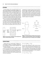
To find the maximum extra tension, T, that will be applied
to any single guy by the force, F; first, determine the pull, P,
which is the amount required along the guys, in the same
vertical plane as the force to resist the horizontal comp onent
Figure 1
10 Pipeline Rules of Thumb Handbook
of the force. This pull is entirely independent of the number
of guys. Assume that the followin g are known:
F ¼The total resultant external force acting on the
structure
G ¼The angle between the horizontal plane and the force
F
h ¼The height of the structure
d ¼The horizontal distance from structure to guy ancho-
rage
m ¼The vertical height of anchorage above or below the
base of the structure
The horizontal component of the force, F, ¼ F cos g.
a ¼The angle whose tangent is (h Æm) Äd.
m is plus if the anchorage is below the base of the
structure and subtracted if it is above.
P ¼F cos g Äcos a
As cos a is always less than 1, P is always greater than F
cos g, the horizontal component of force F.
It must be remembered that P represents the total pull
acting along the guys at an angle, a, with the horizontal, and
in the same vertical plane as the force, F.
If only one guy were used, P would represe nt the extra
tension, T. In practice, however, a number of guys are always
used and, therefore, the pull on any one guy will not be equal
to P. The following table gives factors for any number of guys
from 3 to 15, equally spaced about a central structure. To
find the maximum extra tension, T, that will be applied to
any single guy by the force, F, capable of rotating 360
degrees around a vertical axis, it is only necessary to multiply
the value of P, as determined above, by the factor for the
number of guys used. It must be clearly understood in using
this table that the guys are uniformly spaced and under equal
tension when no load is acting on the structure.
Example. A derrick mast 90 ft high is supported by nine
equally spaced guys anchored at a horizontal distance of 170
ft from the mast and the elevations of the guy anchorages are
10 ft below the base of the mast. The load on the structure is
equivalent to a force of 10,000 lb., acting on an angle of 10
degrees below the horizontal. What is the maximum pull on
any single cable?
From Figure 1—
h ¼90 ft
d ¼170 ft
m ¼10 ft
g ¼10
00
0
F ¼10,000 lb.
tan a ¼
90 þ 10
170
¼ 100 ¼ 0 :588
a ¼30
28
0
P ¼
F cos g
cos a
¼
10;000 Â 0:985
0:862
¼ 11;427 lb:
From Table 1, T ¼11,427 Â0.50 ¼5,714 lb.
If erection tension is 10% of total working tension, 5,714 is
90% of total working tension. Therefore, working tension ¼
(5,714 Â100)/90 ¼6,349 lb.
Table 1
No. of
Guys Factors*
No. of
Guys Factors*
3 1.15 10 0.45
4 1.00 11 0.40
5 0.90 12 0.37
6 0.75 13 0.35
7 0.65 14 0.32
8 0.55 15 0.30
9 0.50
*These factors are for average conditions. If the guys are erected under
accurately measured tensions of not less than 20% of the working load,
the factors for five or more guys may be reduced by 10%. If the
erecting tensions are low or not accurately equalized, the factors for
five or more guys should be increased 10%.
General Information 11
Strength and weight of popular wire rope
The following tables give the breaking strength for wire
rope of popular construction made of improved plow steel.
6 Â19
SIZE Breaking Strength Weight
1
/
4
5,480 0.10
5
/
16
8,520 0.16
3
/
8
12,200 0.23
7
/
16
16,540 0.31
1
/
2
21,400 0.40
9
/
16
27,000 0.51
5
/
8
33,400 0.63
1
3
/
4
47,600 0.90
7
/
8
64,400 1.23
1 83,600 1.60
1
1
/
8
105,200 2.03
1
1
/
4
129,200 2.50
1
3
/
8
155,400 3.03
1
1
/
2
184,000 3.60
1
5
/
8
214,000 4.23
1
3
/
4
248,000 4.90
1
7
/
8
282,000 5.63
2 320,000 6.40
Conversion factors for wire rope of other
construction
To apply the above table to wire rope of other
construction, multiply by the following factors:
Example. Find the breaking strength of 6 Â29 improved
plow steel wire rope 2 in. in diameter.
Strength ¼320,000 Â0.96 ¼307,000 lb.
The weight can be found the same way.
Measuring the diameter of wire rope
Wire rope: field troubles and their causes
All wire rope will eventually deteriorate in operation or
have to be removed simply by virtue of the loads and
reversals of load applied in normal service. There are,
however, many conditions of service or inadvertent
abuse that will materially shorten the normal life of a
wire rope of proper construction although it is properly
applied. The following field troubles and their causes give
some of the field conditions and practices that result in the
premature replacement of wire rope. It should be borne in
mind that in all cases the contributory cause of removal
may be one or more of these practices or conditions.
Wire Rope Construction 6 Â19 6 Â29 6 Â37 18 Â7
Strength Factors 1.00 0.96 0.95 0.92
Weight Factors 1.00 0.97 0.97 1.08
12 Pipeline Rules of Thumb Handbook
Wire-Rope Trouble Cause
a. Rope broken
(all strands).
Overload resulting from severe
impact, kinking, damage, local-
ized wear, weakening of one or
more strands, or rust-bound
condition and loss of elasticity.
b. One or more whole
strands parted.
Overloading, kinking, divider
interference, localized wear, or
rust-bound condition. Fatigue,
excessive speed, slipping, or
running too loosely. Concentra-
tion of vibration at dead sheave
or dead-end anchor.
c. Excessive corrosion. Lack of lubrication. Exposure to
salt spray, corrosive gases, alka-
line water, acid water, mud, or
dirt. Period of inactivity without
adequate protection.
d. Rope damage in
hauling to the well
or location.
Rolling reel over obstructions or
dropping from car, truck, or plat-
form. The use of chains for
lashing, or the use of lever
against rope instead of flange.
Nailing through rope to flange.
e. Damage by
improper socketing.
Improper seizing, which allows
slack from one or more strands
to work back into rope; improper
method of socketing or poor
workmanship in socketing,
frequently shown by rope
being untwisted at socket, loose
or drawn.
f. Kinks, dog legs, and
other distorted
places.
Kinking the rope and pulling
out the loops such as in
improper coiling or unreeling.
Improper winding on the drum.
Improper tie-down. Open-drum
reels having longitudinal spokes
too widely spaced. Divider inter-
ference. The addition of improp-
erly spaced cleats to increase
the drum diameter. Stressing
while rope is over small sheave
or obstacle.
g. Damage by hooking
back slack too
tightly to girt.
Operation of walking beam
causing a bending action on
wires at clamp and resulting in
fatigue and cracking of wires,
frequently before rope goes
down into hole.
h. Damage or failure on
a fishing job.
Rope improperly used on a
fishing job, resulting in damage
or failure as a result of the nature
of the work.
Wire-Rope Trouble Cause
i. Lengthening of
lay and reduction
of diameter.
Frequently produced by some
type of overloading, such as an
overload resulting in a collapse
of the fiber core in swabbing
lines. This may also occur
in cable-tool lines as a result of
concentrated pulsating or surg-
ing forces, which may contribute
to fiber-core collapse.
j. Premature breakage
of wires.
Caused by frictional heat devel-
oped by pressure and slippage,
regardless of drilling depth.
k. Excessive wear in
spots.
Kinks or bends in rope due to
improper handling during instal-
lation or service. Divider interfer-
ence; also, wear against casing
or hard shells or abrasive forma-
tions in a crooked hole. Too
infrequent cut-offs on working
end.
l. Spliced rope. A splice is never as good as a
continuous piece of rope, and
slack is liable to work back and
cause irregular wear.
m. Abrasion and broken
wires in a straight
line. Drawn or
loosened strands.
Rapid fatigue
breaks.
Injury due to slipping rope
through clamps.
n. Reduction in tensile
strength or damage
to rope.
Excessive heat due to careless
exposure to fire or torch.
o. Distortion of wire
rope.
Damage due to improperly
attached clamps or wire-rope
clips.
p. High strands. Slipping through clamps, impro-
per seizing, improper socketing
or splicing, kinks, dog legs, and
core popping.
q. Wear by abrasion. Lack of lubrication. Slipping
clamp unduly. Sandy or gritty
working
conditions. Rubbing
against stationary object or
abra-
sive surface. Faulty alignment.
Undersized grooves and
sheaves.
r. Fatigue breaks in
wire.
Excessive vibration due to poor
drilling conditions, i.e., high
speed, rope slipping, concentra-
tion of vibration at dead sheave or
General Information 13