thermal separation processes
Bạn đang xem bản rút gọn của tài liệu. Xem và tải ngay bản đầy đủ của tài liệu tại đây (26.92 MB, 574 trang )
Klaus
Sattler, Hans
Jacob
Feindt
Thermal
Separation Processes
0
VCH Vcrlagsgescllschaft
mbH,
D-60451
Wcinheim (Federal
Rcpuhlic
ot
Germany).
IWS
Distribution:
VCH,
P.
0.
Box
10
1161.
D-69451
Weinheim. Federal Kcpublic
of
Germany
Switzerland: VCH.
P.O.
Box.
CH-4020 Bascl. Switzerland
LJnitcd Kingdom and Ireland: VCH,
8
Wellington Court. Cambridge
CBI
1HZ.
United Kingdom
USA
and Canada: VCH, 220 East 23rd Street. New York, NY
10010-4606.
USA
Japan:
VCH.
Eikuw Building,
10-9
Hongo 1-chomc. Bunkya-ku, Tokyo
113.
Japan
ISBN
3-527-28622-5
Klaus Sattler, Hans Jacob Feindt
Thermal
Separation
Processes
Principles and Design
Weinheim
-
New
York
Base1
-
Cambridge
-
Tokyo
Prof. Dipl Ing.
Klaus
Sattler
Fachhochschule fur Technik
Speyerer Stral3e
4
D-68163 Mannheim
Dr. Hans Jacob Feindt
BASF AG
Abteilung Verfahrenstechnik
D-67056 Ludwigshafen
This book was carefullyproduced. Nevertheless, authors and publisher donotwarrant the information contai-
ned therein to be free of errors. Readers are advised to keep in mind that statements, data, illustrations, proce-
dural details
or
other items may inadvertently be inaccurate.
Published jointly by
VCH Verlagsgesellschaft. Weinheim (Federal Republic
of
Germany)
VCH Publishers. New York.
NY
(USA)
Editorial Directors: Philomena Ryan-Bugler, Louise Elsam, Karin Sora
Production Manager: Claudia
Gross1
Library of Congress Card
No.
applied
for
A
catalogue record for this book is available from the British Library
Die Deutsche Bibliothek
-
CIP-Einheitsaufnahme
Sattler,
Klaus:
Thermal separation processes
:
principles and design
/
Klaus Sattlcr
;
Hans Jacob Feindt.
-
1.
ed.
-
Wcinhcim
;
Ncw
York
;
Bascl
;
Cambridge
;
Tokyo
:
VCH, 1995
ISBN 3-527-28622-5 (Weinheim
)
NE:
Feindt, Hans Jacob:
0
VCH Verlagsgesellschaft
mbH,
D-69451 Wcinhcim (Federal Rcpublie of Germany), 1995
Printed on acid-free and low-chlorine paper
All
rights reserved (including those
of
translation into other languages). No part
of
this book may be reproduced
in
any form-byphotoprinting,microfilm.or
anyother
means-nortransmittedartranslated
intoamachinelanguage
without written permission
from
the publishers. Registered names, trademarks, etc. used
in
this book. even when
not specifically marked as such,
are
not
to
bc considcrcd unprotected by law.
Composition:
Filmsatz
Unger
&
Sommcr GmbH, D-69469 Weinheim
Printing and Bookbinding: Druck haus ,Thomas Muntzer" GnibH, D-99947 Bad Langcnsalza
Printed
in
the Federal Repuhlie
of
Germany
Foreword
The separation of gaseous and liquid
solu-
tions into their components and the drying
of
wet products have always been an in-
tegral part
of
the manufacture
of
products
in the chemical, petroleum, food, and phar-
maceutical industries.
As
environmental
protection has become an increasingly im-
portant consideration to industry, separa-
tion processes have become more important
in direct proportion.
This book provides a clear fundamental
development
of
the technology of impor-
tant separation processes.
As
indicated by
the title the book deals with separation pro-
cesses in which heat
is
an input to the com-
plete process of separating the constituents
of
a mixture. The flow of heat in the pro-
cess is clear in distillation, crystallization
and drying but is not
so
obvious in absorp-
tion, extraction and adsorption, where the
heat flow is required to regenerate the
sol-
vent or adsorbent.
Each of these six subjects is given
thorough coverage in its own chapter. These
chapters follow
a
comprehensive develop-
ment
of
the physical chemistry and engineer-
ing which provide the principles upon which
the separation processes are based. The in-
dividual process treatments cover computa-
tional algorithms, equipment design criteria
and energy conservation. The overall treat-
ment permits the evaluation of competing
separations techniques and the choice
of
the
optimal process.
This book
is
intended as a college or
university level text for students in chemical
engineering and related fields. It is also com-
plete enough and detailed enough in its
development of each topic to be useful as a
reference for practicing engineers both new
to and experienced in the area
of
separations.
CCNY, New York
May
1994
Prof.
H.
Weinstein
Preface
This book, transformed from the original
German by Dr.
H.
J.
Feindt, is based on
two German editions “Thermische Trenn-
verfahren”, published by Prof.
K.
Sattler.
They have been successfully used as text-
books for university and college students
and as reference texts in seminars and train-
ing programs for practising engineers in
Germany, Austria and Switzerland.
The book presents a clear and very prac-
tice-oriented overview of thermal separa-
tion technologies. An extensive introduc-
tion elucidates the physical, physico-chemi-
cal, and chemical engineering fundamentals
and principles
of
the different unit opera-
tions used to separate homogenous gaseous
and liquid mixtures. The introduction is fol-
lowed by
a
concise text with many explana-
tory figures and tables referring to process
and basic design, flow-sheets, basic en-
gineering and examples for the application
of
the unit operations distillation, absorp-
tion, adsorption, drying, liquid-liquid and
solid-liquid extraction, evaporation and
crystallization of solutions, melt crystalliza-
tion and desublimation. A comprehensive
reference list allows follow up of special
separation problems.
The book enables the reader to choose
and evaluate thermal separation processes
and to model and design the necessary sep-
aration plant equipment.
Chemical and mechanical engineers,
chemists, physisists, bio-technologists in
research and development, plant design,
production, environmental protection and
administration and students in engineering
and natural sciences will find this treat-
ment of exceptional value and practical
use.
Due to the quantity of the topics covered
exercises could not be included in this
book. An additional collection of illustra-
tions with reference to basic engineering
and design of the necessary equipment of
thermal separation units is available in
German (Sattler,
K.
:
Thermische Trennver-
fahren. Aufgaben und Liisungen, Ausle-
gungsbeispiele) and will be translated into
the English language.
We are very much obliged to Prof.
H.
Weinstein, City University of New York
for his advice and his Foreword to this
book. Many thanks are also given to
Philomena Ryan-Bugler, Louise Elsam,
Karin Sora and the production team of
VCH
Verlagsgesellschaft for the accurate
lectorship and book production. Special
thanks are also given to Paul Fursey,
University
of
Bradford, United Kingdom,
for his assistance in copy-editing.
Briihl, Ludwigshafen K. Sattler
December
1994
H.
J.
Feindt
Contents
Frequently Used Nomenclature
XV
1
1.1
1.2
1.3
1.3.1
1.3.2
1.3.3
1.4
1.4.1
1.4.1.1
1.4.1.2
1.4.2
1.4.2.1
1.4.2.2
1.4.3
1.4.3.1
1.4.3.2
1.4.3.3
1.4.3.4
1.4.4
1.4.4.1
1.4.4.2
1.4.5
1.4.5.1
1.4.5.2
1.4.5.3
1.4.5.4
1.4.6
1.5
1.6
Basic Concepts
1
Principles of Thermal Separation Processes
Thermal Separation Process Modes 7
Mass Balance, Energy Balance, Exergy Balance 8
Mass, Energy and Heat Balances
Exergy Balance 12
Calculation of Balance Equations 13
Phase Equilibria 14
Basic Concepts 14
General Differential Equation for the Equilibrium Between
Two Phases 17
The Gibbs Phase Rule 18
Liquid-Liquid Equilibrium 19
The Nernst Distribution Law 19
Representation
of
Liquid-Liquid Phase Equilibrium 23
Vapor-Liquid Equilibrium 28
One Component Systems 28
Two and Multicomponent Systems 30
Henry’s Law, Gas Solubility 44
Boiling Equilibrium of a Solid Solution, Decrease of
Vapor Pressure and Increase of Boiling Point
51
Gas-Solid Phase Equilibrium 52
Gas-Solid Phase Equilibrium, Sublimation 52
Gas-Solid Phase Equilibrium with Adsorption/Desorption and
Convective Solid Drying (Adsorption Equilibrium) 54
Liquid-Solid Phase Equilibrium 60
Solubility of Solids in Liquid Solvents
60
Melting Pressure Curve 62
Decrease in the Freezing Point
State Diagrams
of
Binary Systems for Solid and Liquid Phase
Equilibrium 65
Enthalpy
of
Phase Changes 65
Separation Factor and Relative Volatility 67
Minimum Separation Work 67
1
8
63
X
Contents
1.7
1.7.1
1.7.1.1
1.7.1.2
1.7.1.3
1.7.2
1.7.3
1.7.3.1
1.8
1.9
1.9.1
1.9.2
1.9.3
1.9.3.1
1.9.3.2
1.9.3.3
1.9.3.4
1.9.4
1.9.4.1
1.9.4.2
1.10
1.11
2
2.1
2.2
2.2.1
2.2.2
2.2.3
2.2.4
2.3
2.4
2.5
2.5.1
2.5.1.1
2.5.1.2
Mass Transfer Fundamentals 68
Mass Transfer by Molecular Diffusion
69
Steady-State Diffusion 69
Unsteady-State Diffusion 70
Diffusion Coefficient 70
Mass Transfer by Convection 72
Overall Mass Transfer 74
Two Film Theory, Mass Transfer Coefficient and Turbulence Theory
Steady-State Cocurrent Operation 77
Steady-State Countercurrent Operation 79
Theory of Separation Stages 79
Method to Determine the Number of Theoretical Separation Stages for a
Countercurrent Column 82
Calculation for Counterflow Columns 86
Mass Balances 89
Phase Equilibrium Relationship 89
Enthalpy Balances 89
Stoichiometric Conditions for the Sum of the Concentration
at Each Equilibrium Stage 90
Kinetic Theory for the Counterflow Separation of
a
Mixture 90
Two-Directional Mass Transfer Between Phases 91
One-Directional Mass Transfer 92
Steady-State Crossflow Operation 94
General Procedure to Design Equipment for the Thermal Separation
of Mixtures 94
75
Distillation and Partial Condensation
101
Concepts of Simple Distillation, Rectification and
Partial Condensation 101
Discontinuously and Continuously Operated Simple Distillation,
Flash Distillation 103
Discontinuously Operated Simple Distillation 103
Continuously Operated Simple Distillation 107
Heat Requirement of Simple Distillation Units
Flash Distillation 111
Carrier Distillation 113
Vacuum and Molecular Distillation 116
Countercurrent Distillation (Rectification) 119
Process Variations of Rectification 119
Continuously Operated Rectification in Rectification Columns
with Enriching and Stripping Zones
Stripping (Exhausting) Column 120
109
119
Contents
XI
2.5.1.3
2.5.1.4
2.5.1.5
2.5.1.6
2.5.1.7
2.5.1.8
2.5.1.9
2.5,l.
10
2.5.2
2.5.2.1
2.5.2.2
2.5.2.3
2.5.2.4
2.5.2.5
2.5.2.6
2.5.3
2.5.3.1
2.5.3.2
2.5.3.3
2.5.3.4
2.5.4
2.5.5
2.5.6
2.5.6.1
2.5.6.2
2.6
2.7
2.8
2.9
2.10
Enrichment Column 121
Carrier Rectification 123
Combinations of Different Variations 123
Rectification with an Entrainer 123
Heteroazeotropic Rectification 129
Two Pressure Operation 130
Diffusion Distillation 131
Overpressure,
Low
Temperature and Vacuum Rectification
Continuous Adiabatic Rectification 134
Flow Rates 135
Heat Requirement of
a
Column
Energy Saving Steps 138
Determination of the Number
of
Separation Stages and Column
Height for Heat and Mass Transfer
Minimum Reflux Ratio, Optimal Economic Reflux Ratio 157
Feed Stage 157
Discontinuous Adiabatic Rectification 158
Amount of Overhead Product 160
Heat Requirement 161
Still Diameter, Free Vapor Space, Column Diameter
McCabe-Thiele Method to Determine the Number of Theoretical Separation
Stages 163
Semicontinuous Adiabatic Rectification 163
Determination
of
the Column Diameter 164
Internals in Rectification Columns 165
Column Trays 167
Random Packing, Packing with Regular Geometry 196
Choice, Optimization and Control of Rectification Units 216
Rectification Units Accessories 218
Parallel Flow Distillation 222
Nonadiabatic Rectification 222
Partial Condensation 230
132
136
147
162
3
Absorption
239
3.1
3.1.1 Concepts and Process Examples 239
3.1.2 Process Examples 240
3.2
3.3 Enthalpy and Heat Balances 246
3.4 Cocurrent Phase Flow Absorption 248
Principle of Absorption and Desorption, Processes and Process
Examples 239
Requirements of the Wash Liquid or Solvent, Solvent Consumption 243
XI1
Contents
3.5
3.5.1
3.5.2
3.6
3.7
4
4.1
4.1.1
4.1.2
4.2
4.2.1
4.2.2
4.2.3
4.3
4.4
4.4.1
4.4.2
4.4.3
4.5
4.6
5
5.1
5.2
5.3
5.4
5.5
5.6
5.6.1
5.6.2
5.6.3
5.1
5.8
Countercurrent Phase Flow Absorption, Design of Countercurrent Flow
Columns 248
Determination of the Column Cross-Sectional Area 248
Determination of the Number of Stages and Column Height for Mass and
Heat Transfer 250
Types of Absorber 262
Regeneration
of
the Solvent, Desorption 263
Adsorption 281
Principles
of
Adsorption and Desorption, Processes and Examples
28
1
Concept 281
Processes and Examples 282
Adsorbents, Selection of Adsorbent 291
Adsorbents 291
Requirements for the Adsorbent, Adsorbent Selection
Technical Adsorbents, Characteristic Data of Adsorbents 293
Adsorption Kinetics 293
Variation of Adsorption, Design of Adsorbers 301
Single Stage Adsorption in
a
Vessel Adsorber with Adsorbent Packing 301
Multistage Adsorption with Cross Flow of Gas and
Adsorbent Phases 307
Multistage Countercurrent Adsorption 308
Adsorber Types 310
Desorption, Regeneration
of
Loaded Adsorbent 31 1
291
Drying
317
Concepts, Processes and Examples 317
Characteristics of the Moist Product, Movement of Moisture
Properties of Wet Gases,
h-X
Diagram
Mass and Heat Transfer in Convection Drying 331
Drying Kinetics, Course of Drying, Drying Time
Convection Drying 340
Drying Gas and Heat Requirements in Convection Drying 340
Steps in Energy Saving 343
Variations of Convection Drying 346
Contact Drying 349
Radiation Drying 351
320
324
335
Contents
XI11
5.9 Dielectric Drying 352
5.10 Freeze Drying (Sublimation Drying) 355
5.11
5.11.1
5.11.2
5.1
1.2.1
5.11.2.2
5.1 1.2.3
5. 11.2.4
5.11.2.5
5.11.2.6
5.11.2.7
5.1 1.2.8
5.11.2.9
5.1 1.2.10
5.1 1.2.11
5.11.2.12
5.11.3
Design
of
Dryers 357
Overview of Dryers, Dryer Selection and Design 357
Individual Presentation of Selected Dryer Types with Design Aids 363
Chamber Dryer 363
Tunnel Dryer 364
Belt Dryer 364
Multiple Plate Dryer 364
Rotary Dryer 364
Fluidized Bed Dryer 366
Air-Flow Dryer, Pneumatic (Flash) Dryer 374
Spray Dryer 377
Drum Dryer 381
Thin Film Evaporation Dryer
(Vertical and Horizontal Dryer) 381
Contact-Mixing Dryer 381
Contact Dryer with Continuous Product Movement due to Gravity 385
Process Control of Dryers 387
6
Extraction
393
6.1 Basic Concepts and Processes 393
6.2
6.2.1
6.2.2
6.2.3
6.2.3.1
6.2.3.2
6.2.3.3
6.2.3.4
6.2.3.5
6.2.3.6
6.2.4
6.2.4.1
6.2.4.2
6.2.5
Liquid-Liquid Extraction 395
Fields of Application and Process Examples
Solvent Requirements, Selection
of
Solvent 399
Liquid-Liquid Extraction Variations 400
Single Stage Extraction 400
Differential Stagewise Extraction 403
Multistage Cross-Current Extraction 403
Multistage Countercurrent Extraction 407
Countercurrent Extraction with Extract Reflux 421
Countercurrent Distribution 424
Design Forms
of
Extraction Apparatus 424
Mixer-Settler, Mixer-Settler Cascade 425
Countercurrent Columns with and without Energy Supply 426
Selection and Design of Extraction Apparatus 456
395
6.3 Solid-Liquid Extraction (Leaching) 458
6.4 High Pressure Extraction (Distraction) 463
XIV
7
7.1
7.2
7.2.1
7.2.1.1
7.2.1.2
7.2.1.3
7.2.1.4
7.2.1.5
7.2.2
7.2.2.1
7.2.2.2
7.2.3
7.2.4
7.2.5
7.2.6
7.2.7
7.3
7.4
8
Contents
Solvent Evaporation, Crystallization
475
Basic Concept and Processing Modes of Crystallization
Crystallization from a Solution
484
Concentration of Solutions by Evaporation
485
Single Stage Solution Evaporation
486
Multistage Solution Evaporation
487
Solution Evaporation with Mechanical and Thermal Vapor
Compression
492
Multistage Flash Evaporation
498
Types of Evaporators to Concentrate Solutions
500
Balancing
of
Crystallizers
500
Crystal Product Rate
500
Heat Exchange During Crystallization
506
Crystallization Kinetics, Crystal Seed Formation, Crystal Growth
508
Design of Crystallizers for Mass Crystallization from a Solution
511
Criteria for the Selection and Design of Crystallizers
516
Freezing
519
Fractional Crystallization
of
a
Solution
Crystallization from a Melt
521
Crystallization from a Vapor Phase, Sublimation and Desublimation
524
475
520
Documentation and Calculation
of
Physical Characteristics
533
General References
537
Index
539
Frequently Used Nomenclature
A
AQ
D
D, D
E
F
F
fiF
F
G,
G
G
H
HE
TS
HTU
K*
L,
L
Lc
M
N
NTU
Q,
Q
R,
R
R
S
Area
Cross sectional area, cross section
Diffusion coefficient
Vapor; vapor flow rate
Enrichment ratio, stage efficiency factor
Force
Loading factor for column trays
Feed; feed flow rate
Free internal energy
Gas; gas flow rate
Free enthalpy, Gibbs free energy
Enthalpy
Height equivalent to one theoretical stage
Height of
a
transfer unit
Phase equilibrium constant, distribution coefficient
Liquid; liquid flow rate
Characteristic length
Molar mass
Number of stages
Number of transfer units
Heat; heat flow rate
Reflux; reflux flow rate
Gas constant
Entropy
m2
m2
m2/h
kg, kmol; kg/h,
kmol/h
N
m/s
.
vm
=
1/pa
kg, kmol; kg/h,
kmol/h
kJ
kg, kmol; kg/h,
kmol/h
kJ
kJ
m
m
kg, kmol; kg/h,
kmol/h
m
kg/kmol
kJ; kJ/h,
W
kg, kmol; kg/h,
kmol/h
kJ/(kmol
+
K)
k
J/K
XVI
Frequently Used Nomenclature
T
Absolute temperature
K
U
Internal energy
V,
V
v
Molar volume
W
Work
Volume; volumetric
flow
rate
kJ
m3; m3/h
m3/kmol
kJ
x
Ratio or loading
of
key component in liquid or
heavy phase (moles i/moles inert, kg i/kg carrier
(inert))
-
Ratio or loading of key component in vapor or
light phase (moles i/moles inert, kg i/kg carrier
(inert))
Y
Z
Length or height for heat and mass transfer
a
Activity
a
Specific volumetric area
cp,
Cp
Specific heat
c
Molar concentration
cw
Resistance coefficient
d
Diameter
dP
Particle diameter
ds
Sauter diameter
f
Fugacity
.Lf
Specific free internal energy
g
gravitational acceleration
g9
E
Specific free enthalpy
h,
Specific enthalpy
Ah,
A&
Latent heat
k
Overall heat transfer coefficient
k
Overall mass transfer coefficient
rn,
m
Mass; mass
flow
rate
n,
n
Number of moles; molar flux
P
Total pressure
P,
Partial pressure
of
component
i
m
m2/m3
kJ/(kg.
K),
kJ/(kmol.
K)
kmol/m3
m
m
m
bar
kJ/kg, kJ/kmol
m/s2
kJ/kg, kJ/kmol
kJ/kg, kJ/kmol
kJ/kg, kJ/kmol
W/(m2.
K)
m/h
kg; kg/h
kmol; kmol/h
bar, Pa
bar, Pa
Frequently
Used
Nomenclature
XVII
Po,
i
AP
Pressure drop
4
Specific heat requirement
4
Specific heat
flux
r
Radius
r
Reaction rate
s,
s
Specific entropy
Saturated vapor pressure of component
i
S
t
t,n
u,
ii
W
W
X
Y
Z
Az
Greek
a
a
Characteristic distance (transfer distance)
Time
Mean residence time
Specific internal energy
Velocity
Mass fraction, weight fraction
of
component
i
Molar fraction, heavy phase
Molar fraction, light phase
Variable distance length or height
Tray spacing
Separation factor
Heat transfer coefficient
Mass transfer coefficient
Activity coefficient
Film thickness, layer thickness
Porosity, void fraction of a bed of solids,
fraction
of
free volume
Yield
Dynamic viscosity
Temperature
Slope, gradient angle, inclination
Thermal conductivity
Chemical potential
bar, Pa
mbar, Pa
kJ/kg
kJ/(m2 h), W/m2
m
kmol/(m3
-
h)
kJ/(kmol
K)
m
h
h
k
J/kg, k J/kmol
m/s
kJ/(kg.
K),
m
-
W/(m2.
K)
m/h
m
-
Pa
-
s
"C
0
W/(m
.
K)
k J/kg, kJ/kmol
XVIII
Frequently
Used
Nomenclature
V
V
Kinematic viscosity
e
Density
0
Surface tension
v?
Relative humidity
Reflux ratio, solvent ratio, adsorbent ratio
Subscripts
H
T
g
is
J
1
0
P
S
t
U
U
a
0
Steam
Carrier
Gas
phase
Component
Liquid phase
Above, surface
Effective, practical
Solid phase
Theoretical
Below
Loss
Start, entry
End, exit
-
m2/s
kg/m3
N/m
-
Basic
Concepts
1.1
Principles
of
Thermal Separation Processes
In a chemical
production plant,
products
are produced by the chemical and physical
conversion of raw materials or intermediate
products. The production unit is a com-
pletely integrated technical operating unit
on the site. It is connected with other units
on
the site by transportation and personnel
routes, and pipelines for raw materials, aux-
iliary substances, products, utilities, and en-
ergy. It usually consists of the actual pro-
duction unit and several off-site facilities, as
shown in Fig. 1-1.
The main unit contains the
unitprocesses
and operations,
such as separation, combi-
nation, division, formulation, heat trans-
fer, conveying, storage, packing. Figure 1-2
shows
a
general set-up which is independent
from the type of process. The combination
of unit processes and operations with re-
spect to product properties depends on the
product produced.
During the chemical conversion of raw
materials,
homogeneous
and
heterogeneous
mixtures (Figs. 1-2 and 1-3) are generated.
Both reactants and products may be found
in these mixtures, according to the yield
and conversion of the chemical reaction.
By means of thermal separation processes
these mixtures must be treated to obtain the
desired products to a demanded purity and
to enable the raw materials
to
be recycled.
Processes to separate physically homo-
geneous (one phase) and heterogeneous
(two or multiphase) mixtures are listed
in
Table 1-1. The driving force of the separa-
tion process usually forms the criteria for
the separation. Homogeneous mixtures
with
a
molecularly dispersed distribution of
individual components may only be sepa-
rated by means
of
a
thermal separation pro-
cess.
Thermal separation processes
are mass
transfer operations, driven by molecular
forces. Mass, and often heat, is exchanged
between
at
least two phases of different
composition. The phases are the mixture
phase(s) and a selective auxiliary phase. The
auxiliary phase is generated by either add-
ing heat and/or by means of an auxiliary
substance. The required driving forces, con-
centration, and temperature gradients, are
formed due to the auxiliary phase.
In Fig. 1-4 thermal separation processes
are listed and are denoted by the phases
contributing to mass transfer in Table 1-2.
Thermal separations of mixtures are car-
ried out in the following individual steps
:
-
Step
1
:
An additional phase is generated
by supplying energy to the system, or by
adding an auxiliary component.
-
Step
2:
Mass, and often simultaneously
heat, is exchanged between phases. This
is achieved by the addition or removal of
energy.
-
Step
3:
After completion of the inter-
change process, the phases are separated.
Together with the separation of the
phases
a
(partial) separation of the mix-
ture occurs.
All thermal separation processes follow
this order
of
events. The
basic principles
of
thermal separation processes are now for-
mulated and will be discussed in detail.
Thermal Separation Processes:
Principles
and
Design
Klaus Sattler, Hans Jacob Feindt
copyright
0
VCH
Verlagsgesellschaft
mhH,
1995
2
1
Basic Concepts
Inputs
-+
Energy
-+
Raw
-
materials
Auxiliary
-
materials
Main plant
Process consisting of physical and chemical unit operations
to
produce desired products
Off-sites, auxiliary equipment
-
process control of the main plant
control room sometimes with
a
process control computer,
control devices for drives, production lab, instrument air sta-
tion
-
supply
of
energy to main plant, generation and distribution
of
electrical power, heating system for heating media such as
hot water, steam, dyphil, salt melts
-
provision
of
auxiliary materials (adjuvants) such as heat
transfer media, coolants, catalysts, solvents, inerts
-
storage of raw and auxiliary materials, and products, spare
parts, tools and materials for repair work and maintenance
~~
~~~
~_~
-
transport to the process unit
of
the raw material and auxiliary
materials, transport
of
the products (roads, rail connections,
harbor)
-
disposal
treatment
of
waste gas and wastewater, reprocessing of solid
residue and waste disposal
_~
-
__
__
-
facilities for the operating personnel
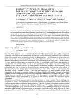
Fig.
1-1.
General production process set-up.
Raw material
I
Excess
energy
*
Main
products
-+
By-products
+
Waste
+
Waste gas
-+
Wastewater
metering, preheating
~
Path
of
raw material or
product
Fig.
1-2.
Basic flow chart for the
main part
of
a
production plant.
i
Main
product ready
for
storage
or
shipment
1.1
Principles
of
Thermal Separation Processes
1
Y
1
Y
A
r
Y
Reaction mixture
Ab::+
3
Phases
in
Cocurrent
Flow
(Principle
of
Parallel Flow)
Phases
in
Countercurrent
Flow
(Principle
of
Counterflow)
Phases taking place in mass and heat trans- Phases taking place in mass and heat trans-
fer are guided in cocurrent flow through the fer are guided in countercurrent flow
separation apparatus. The maximum effi- through the separation apparatus. In this
ciency of this separation apparatus is the case it
is
important to disperse the phases
same as that for a single theoretical separa- with the aid of internals, thereby achieving
tion stage.
intensive mixing of the phases. Thus the
I
Rectification
I
(counterflow distillation)
1
counterflow crystallimtion
I
from a melt
Partial distillation
Partial condensation
Absorption
Extraction
:
Counterflow sublimation Adsorplion
I
Counterflow liquid-liquid extraction
~
Cristallization from
a
solution
Drying
Fractionating,
Counterflow
~
phase
processes transformation
i
1
Thermal
\epnratioii
I_._________
Pro-
I
cesres
with
auxiliary
L
materials
Absorption
Adsorption
Convective drying
Carrier distillarion
Extractive distillation
Extraction
Entrainer gas sublimation
Distillation
Partial condensation
Crystallization
Drying (except convective drying)
Vacuum dhmation
Principle of classification.
r l
,_
- -
_,
Simple phase transfomiation
t)
fractionating
Auxiliary product: required for
separation
tf
not required tor
separation
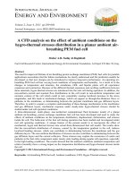
Fig.
1-4.
Summary
of
thermal separation processes.
4
1
Basic Concepts
Table
1-1.
Summary of separation processes.
Classes
of
Driving force Nature
of
Separation processes
separation
of
separation mixture
processes process
Mechanical
separations
Membrane
separation
Electrical
separation
Magnetic
separation
Thermal
separation
Gravity
Centrifugal force
Pressure
Pressure
Electrical field
Concentration
gradient
Electrical field
Magnetic field
Concentration
gradient
Temperature
gradient
Heterogeneous
Heterogeneous
Homogeneous
Heterogeneous
Homogeneous
Homogeneous
Sorting
(s
-
s)
Dense-media separation
(s
-
1)
Flotation
(s
-
1
-
g)
Sedimentation
(s
-
1)
Filtration
(s
-
1)
Pressing
(s
-
I)
Centrifugation
(s
-
1)
Hydrocyclone separation
(s
-
1)
Classification
Sieving
(s
-
s)
Air classification
(s
-
g)
Hydraulic classification
(s
-
1)
Ultrafiltration
(s
-
1)
Reverse osmosis (hyperfiltration)
(s
-
1)
Dialysis
(s
-
1)
Electrodialysis
(s
-
1)
Electrophoresis
(s
-
1)
Permeation
(1
-
1,
g
-
g)
Gas diffusion (g
-
g)
Electro osmosis
(s
-
1)
Electrical dust removal
(s
-
g)
Magnetic separation
(s
-
s)
Distillation
(1
-
1)
partial condensation (g
-
g)
Absorption (g
-
g), (A)
Adsorption (g
-
g,
s
-
I),
(A)
Chromatography (g
-
g,
1
-
1)
Extraction
(s
-
s,
1
-
I),
(A)
Sublimation (g
-
g)
Crystallization
(s
-
1,
1
-
1)
Drying
(s
-
1)
Thermal diffusion (g
-
g,
1
-
1)
~
Abbreviations:
s
solid,
1
liquid, g gas to characterize the state of the components of the mixture to
be separated, (A) thermal separation process with auxilliary component.
maximum possible interfacial area (phase
boundary) for mass transfer is obtained
and, hence, the highest possible mass trans-
fer coefficient values. Figure
1-5
shows
a
“separation column” with stages connected
in series in which the key component
i
of
a
mixture is exchanged from the heavy phase
to the light phase. Both phases may contain
all components of the mixture.
A
closer
inspection
of
stage
n
shows that
the heavy phase, with
a
mole fraction
of
x,,
is
in contact with the light phase with a
1.1
Principles
of
Thermal Separation Processes
5
Table 1-2.
Characteristics of thermal separation processes by the phases in which mass and heat
transfer occurs.
~~
Phase Phase All components Not all components are in both phases
1
2
are contained
Phase
1
Phase
2
One (several) com-
pure
pure ponent
(s)
is (are)
in both phases
in both phases
Immiscible g
1
phases in
contact
g
S
g g
1
1
1
S
S
S
Miscible g g
phases in
contact
1 1
S
S
Distillation
Partial
condensation
Counter current
sublimation
Liquid-liquid
extraction
Crystallization
from a melt
Thermal
diffusion
Thermal
diffusion
-
Concen-
tration
of
solutions
-
~
Gas
drying
Crystal-
lization
from a
solution
~~
Absorption
Desorption by
stripping
Adsorption
Drying
Solid-liquid
extraction
(leaching)
Adsortpion
Abbreviations: g gas phase,
1
liquid phase,
s
solid phase.
mole fraction
of
Y,,-~.
If
x,
and are
not phase equilibrium concentrations, the
fed phases of stage
n
are not in phase equi-
librium, and mass and heat transfer take
place. The key component
i
becomes en-
riched in the light phase up to a final con-
centration
y,,
while the heavy phase is re-
duced
in
component
i
from
x,,
to
x,-~.
With stage
n
as a theoretical separation
stage, the leaving phases are in equilibrium
and
no
further mass or heat transfer is pos-
sible. Therefore,
y,
and
x,-~
are phase
equilibrium concentrations.
The heavy phase, with concentration
x,,
-
arrives at stage
n
-
1 and comes into
contact with the light phase, with concen-
tration
ynP2.
An exchange, similar to that
in stage
n,
takes place.
The discussed example shows that for
countercurrent phase flow, single stages are
connected in series in one separation appa-
ratus. The light phase leaving
a
stage is
guided to the following stage whereas the
heavy phase is guided to the previous stage.
A theoretical stage
is that part of a sepa-
ration apparatus where mass or heat trans-
fer take place in which entering phases are
not in phase equilibrium, while the leaving
phases have reached
phase equilibrium
(see
Chapter
1.4).
In
a
practical separation stage, equilib-
rium is often not achieved. The efficiency
6
1
Basic Concepts
HP
LP
L-l r
transfer ratio, depending on whether
y
is
only locally valid or constant across the
cross section of the column.
Phases
in
Cross
Flow
(Cross Flow Principle)
Phases taking part in mass and heat trans-
fer flow across through the separation ap-
paratus at an angle of
90"
to each other.
The separation efficiency depends on the
equilibrium location and the ratio of the
phase fluxes, but is often low in an individ-
ual separation stage.
To
separate
a
mixture
Fig.
1-5.
Countercurrent flow of two phases in a
and obtain pure products, several separa-
separation apparatus.
n
-
1,
n
Stages connected in series
tion stages are connected in series. This is
LP
Upflowing light phase
done most effectively with countercurrent
HP
Downflowing heavy phase
phase flow. Phase cross flow and parallel
x
feed of one phase to individual separation
stages are sometimes used. However, cocur-
y
rent flow is of non importance.
Molar fraction of the key component in
the heavy phase
Molar fraction
of
the key component in
the light phase
compared with a theoretical stage
is
ex-
pressed as the
stage efficiency factor,
E
(ex-
change ratio, enrichment ratio,
MURPHREE
efficiency) (Fig.
1-5):
~i~~
Requirement
The time needed to separate a mixture in
a
discontinuous operation is the effective resi-
dence time. For continuous operation, it is
in the separation apparatus:
separation effect of
a
practical stage
the
mean residence time
t,,
of the mixture
E=
separation effect
of
a
theoretical stage
Yn-Yn-1
E=
Yn*-Yn-1
V
V
(1-1)
t,
=
T
where where
y,*
-
y,-,
possible theoretical enrichment
of the key component in the
light phase
(y;
phase equilib-
rium concentration at
x,
-
y, -ynp1
actual enrichment of the key
component in the light phase
This often has to be distinguished as a local
transfer ratio, as opposed to an overall
I/
filled volume of the mixture in the sepa-
ration apparatus (determined by the
volume
of
the apparatus and the degree
of filling)
effective volumetric flow of the mixture
Short-, medium- and long-term separation
processes can be distinguished depending
on the time requirement:
1.2
Thermal Separation Process Modes
7
-
Short-term processes (t,
<
30
sec).
Examples: Spray drying, gas adsorption,
precipitation crystallization.
-
Medium-term processes
(30
sec<
t,
<
2h).
Examples: Absorption, rectification, drum
drying, pneumatic-conveyor drying, sub-
limation, extraction, crystallization, liq-
uid adsorption.
Examples
:
Rotary drum drying, vacuum
tumbling drying, vacuum freeze drying,
fractionation crystallization.
-
Long-term processes
(1
h
<
t,
<
1
d).
Energy
Supply
-
Flow
energy,
for pressure drops in the ap-
paratus and the connecting pipework.
-
Mechanical energy,
for example for dis-
persing, pulsing, stirring and pump cir-
culation devices.
-
Work,
to operate peripheral machines
such as compressors and vacuum pumps.
1.2
Thermal Separation
Process Modes
Apparatus for the thermal separation of
mixtures may be operated both
discon-
tinuously
(intermittently, batch production,
stagewise operation) and
continuously
(steady-state). In the following section, the
operating modes are briefly illustrated. The
For the thermal separation
of
a mixture in
an apparatus, energy has to be supplied in
the form of:
-
Heat,
to increase the sensible heat of the
flowing masses and to supply latent heat.
advantages and disadvantages are listed in
Table
1-3.
Table 1-3.
Comparison of continuous and discontinuous operation to achieve
the
same separation
problem.
Comparison criteria Operating mode
Continuous Discontinuous
Mathematical description of
the
separation process,
modeling
Investment cost
of
separation unit
Operating cost
of
separation unit
Operation of separation
unit
Automatic control of separation process
Working
stress
on unit components
Environmental pollution,
possibility
of accident
Operation reliability, flexibility in
the
case
of
breakdown
of separation unit parts, safety buffer
Flexibility
to
adjust to other mixtures to be separated
Simpler
Less
Less
Easier
Possible with
less expense
Less
Less
Higher
Better
8
1
Basic Concepts
Continuous Operation
:
In continuous op-
eration the mixture being separated is con-
tinuously fed to the separation device. It is
continuously separated into two or more
fractions, which are continuously with-
drawn from the separation device.
An ideal binary mixture can be separated
into almost pure components in a separa-
tion column operated continuously with
countercurrent flow.
To
separate a mixture
of
k
components,
k
-
1
columns connected
in series are needed.
Discontinuous Operation:
With discontin-
uous operation the mixture being separated
is charged to the separation device. During
a time period, the “batch period”, the mix-
ture is separated mainly into two fractions
of defined different compositions. One
fraction is continuously withdrawn from
the separation device, while the other re-
mains in the device and is withdrawn at the
end of the batch time.
Discontinuously operated processes
-
mainly in one stage
-
allow incomplete
separation of a mixture; the obtained frac-
tions are treated in subsequent stages (this is
the case for multistage discontinuous sepa-
ration).
Alternating Operation
:
If
in a separation
apparatus after a loading process (separa-
tion of a mixture) an unloading process (the
regeneration
of
a
substance aiding separa-
tion) is required, at least two sets of equip-
ment are operated alternately. Therefore,
steady separation of the mixture is guaran-
teed.
In the case of the adsorption of a sub-
stance from
a
gas phase in a container ad-
sorber (see Chapter
4),
for example,
a
solid
fsum
of amount)
f
sum
of amount
)
adsorbent adsorbes adsorbate (key compo-
nent in the gas phase). Adsorption contin-
ues to an upper loading limit. After the
maximum load has been reached in the first
adsorber, operation is switched to the sec-
ond adsorber. The loaded adsorber is then
regenerated by dampening, drying and
cooling. After the regeneration cycle is fin-
ished, the adsorber
is
ready for loading
again.
1.3
Mass Balance,
Energy Balance, Exergy Balance
In general, the first step in the design of
a
separation plant
is
the
balancing
of individ-
ual apparatuses and parts of the plant. Bal-
ances are done with respect to energy and
mass fluxes, in connection with
a
schematic
representation of the process (flow dia-
gram).
1.3.1
Mass, Energy and
Heat Balances
The balancing
of
chemical engineering sys-
tems follows the sequence listed in Fig.
1-6.
Of the variables listed for process design,
mass and energy (usually
in
the
form
of
heat, enthalpy, and exergy) are of most in-
terest. These variables may also be used for
planning, evaluation
of
systems, analysis,
and synthesis.
Based on the laws of conservation of
mass, energy and momentum, balance
equations are set up
[1.1]
-
[1.5].
For a
gen-
eral open system
fsum of amount)
f
increase
of
\
entering generated in leaving mass stored
-k
1
in the system
(transport) (transformation) (transport) (accumulation)
[
the system
+
[
the system
=
1
the system