introduction to thermal systems engineering thermodynamics, fluid mechanics, and heat transfer
Bạn đang xem bản rút gọn của tài liệu. Xem và tải ngay bản đầy đủ của tài liệu tại đây (14.57 MB, 801 trang )
Michael J. Moran
The Ohio State University
Howard N. Shapiro
Iowa State University of Science and Technology
Bruce R. Munson
Iowa State University of Science and Technology
David P. DeWitt
Purdue University
John Wiley & Sons, Inc.
Introduction to Thermal
Systems Engineering:
Thermodynamics, Fluid Mechanics,
and Heat Transfer
fm.qxd 6/27/02 12:50 Page i
Acquisitions Editor Joseph Hayton
Production Manager Jeanine Furino
Production Editor Sandra Russell
Senior Marketing Manager Katherine Hepburn
Senior Designer Harold Nolan
Production Management Services Suzanne Ingrao
Cover Design Howard Grossman
Cover Photograph © Larry Fleming. All rights reserved.
This book was typeset in 10/12 Times Roman by TechBooks, Inc. and printed and bound by R. R. Donnelley
and Sons (Willard). The cover was printed by The Lehigh Press.
The paper in this book was manufactured by a mill whose forest management programs include sustained yield
harvesting of its timberlands. Sustained yield harvesting principles ensure that the number of trees cut each year
does not exceed the amount of new growth.
This book is printed on acid-free paper. ϱ
Copyright © 2003 by John Wiley & Sons, Inc. All rights reserved.
No part of this publication may be reproduced, stored in a retrieval system or transmitted in any form or by any
means, electronic, mechanical, photocopying recording, scanning or otherwise, except as permitted under
Sections 107 or 108 of the 1976 United States Copyright Act, without either the prior written permission of the
Publisher or authorization through payment of the appropriate per-copy fee to the Copyright Clearance Center,
222 Rosewood Drive, Danvers, MA 01923, (508) 750-8400 fax (508) 750-4470. Requests to the Publisher for
permission should be addressed to the Permissions Department, John Wiley & Sons, Inc. 605 Third Avenue,
New York, NY 10158-0012, (212) 850-6008, E-mail: To order books or for customer
service call 1-800-CALL-WILEY(225-5945).
ISBN 0-471-20490-0
Printed in the United States of America.
10987654321
fm.qxd 6/27/02 12:50 Page ii
O
ur objective is to provide an integrated introductory
presentation of thermodynamics, fluid mechanics,
and heat transfer. The unifying theme is the application of
these principles in thermal systems engineering. Thermal
systems involve the storage, transfer, and conversion of en-
ergy. Thermal systems engineering is concerned with how
energy is utilized to accomplish beneficial functions in
industry, transportation, the home, and so on.
Introduction to Thermal Systems Engineering: Thermo-
dynamics, Fluid Mechanics, and Heat Transfer is intended
for a three- or four-credit hour course in thermodynamics,
fluid mechanics, and heat transfer that could be taught in
the second or third year of an engineering curriculum to
students with appropriate background in elementary
physics and calculus. Sufficient material also is included
for a two-course sequence in the thermal sciences. The
book is suitable for self-study, including reference use in
engineering practice and preparation for professional en-
gineering examinations. SI units are featured but other
commonly employed engineering units also are used.
The book has been developed in recognition of the team-
oriented, interdisciplinary nature of engineering practice,
and in recognition of trends in the engineering curriculum,
including the move to reduce credit hours and the ABET-
inspired objective of introducing students to the common
themes of the thermal sciences. In conceiving this new
presentation, we identified those critical subject areas
needed to form the basis for the engineering analysis of
thermal systems and have provided those subjects within
a book of manageable size.
Thermodynamics, fluid mechanics, and heat transfer are
presented following a traditional approach that is familiar
to faculty, and crafted to allow students to master funda-
mentals before moving on to more challenging topics. This
has been achieved with a more integrated presentation than
available in any other text. Examples of integration include:
unified notation (symbols and definitions); engaging case-
oriented introduction to thermodynamics, fluid mechanics,
and heat transfer engineering; mechanical energy and
thermal energy equations developed from thermodynamic
principles; thermal boundary layer concept as an exten-
sion of hydrodynamic boundary layer principles; and more.
Features especially useful for students are:
•
Readable, highly accessible, and largely self-
instructive presentation with a strong emphasis on
engineering applications. Fundamentals and
applications provided at a digestible level for an
introductory course.
•
An engaging, case-oriented introduction to thermal
systems engineering provided in Chapter 1. The
chapter describes thermal systems engineering gen-
erally and shows the interrelated roles of thermody-
namics, fluid mechanics, and heat transfer for ana-
lyzing thermal systems.
•
Generous collection of detailed examples featuring
a structured problem-solving approach that encour-
ages systematic thinking.
•
Numerous realistic applications and homework prob-
lems. End-of-chapter problems classified by topic.
•
Student study tools (summarized in Sec. 1.4)
include chapter introductions giving a clear
statement of the objective, chapter summary and
study guides, and key terms provided in the
margins and coordinated with the text
presentation.
•
A CD-ROM with hyperlinks providing the full
print text plus additional content, answers to
selected end-of-chapter problems, short fluid flow
video clips, and software for solving problems in
thermodynamics and in heat transfer.
•
Access to a website with additional learning
resources: />Features especially useful for faculty are:
•
Proven content and student-centered pedagogy
adapted from leading textbooks in the respective
disciplines:
M.J. Moran and H.N. Shapiro, Fundamentals of
Engineering Thermodynamics, 4
th
edition, 2000.
B.R. Munson, D.F. Young, and T.H. Okiishi,
Fundamentals of Fluid Mechanics, 4
th
edition,
2002.
F.P. Incropera and D.P. DeWitt, Fundamentals of
Heat and Mass Transfer, 5
th
edition, 2002.
•
Concise presentation and flexible approach readily
tailored to individual instructional needs. Topics
are carefully structured to allow faculty wide
latitude in choosing the coverage they provide to
students—with no loss in continuity. The accom-
panying CD-ROM provides additional content that
allows faculty further opportunities to customize
their courses and/or develop two-semester
courses.
Preface
iii
fm.qxd 6/27/02 12:50 Page iii
iv Preface
•
Highly integrated presentation. The authors have
worked closely as a team to ensure the material
is presented seamlessly and works well as a whole.
Special attention has been given to smooth transitions
between the three core areas. Links between the core
areas have been inserted throughout.
•
Instructor’s Manual containing complete, detailed
solutions to all the end-of-chapter problems to assist
with course planning.
A Note on the Creative Process
How did four experienced authors come together to
develop this book? It began with a face-to-face meeting in
Chicago sponsored by our Publisher. It was there that we
developed the broad outline of the book and the unifying
thermal systems engineering theme. At first we believed it
would be a straightforward task to achieve our objectives
by identifying the core topics in the respective subject areas
and adapting material from our previous books to provide
them concisely. We quickly found that it was easier to agree
on overall objectives than to achieve them. Since we come
from the somewhat different technical cultures of thermo-
dynamics, fluid mechanics, and heat transfer, it might be
expected that challenges would be encountered as the
author team reached for a common vision of an integrated
book, and this was the case.
Considerable effort was required to harmonize different
viewpoints and writing styles, as well as to agree on the
breadth and depth of topic coverage. Building on the good
will generated at our Chicago meeting, collaboration
among the authors has been extraordinary as we have taken
a problem-solving approach to this project. Authors have
been open and mutually supportive, and have shared com-
mon goals. Concepts were honed and issues resolved in
weekly telephone conferences, countless e-mail ex-
changes, and frequent one-to-one telephone conversations.
A common vision evolved as written material was
exchanged between authors and critically evaluated. By
such teamwork, overlapping concepts were clarified, links
between the three disciplines strengthened, and a single
voice achieved. This process has paralleled the engineer-
ing design process we describe in Chapter 1. We are
pleased with the outcome.
We believe that we have developed a unique, user-
friendly text that clearly focuses on the essential aspects
of the subject matter. We hope that this new, concise
introduction to thermodynamics, fluid mechanics, and heat
transfer will appeal to both students and faculty. Your
suggestions for improvement are most welcome.
Acknowledgments
Many individuals have contributed to making this book
better than it might have been without their participation.
Thanks are due to the following for their thoughtful com-
ments on specific sections and/or chapters of the book:
Fan-Bill Cheung (Pennsylvania State University), Kirk
Christensen (University of Missouri-Rolla), Prateen V.
DeSai (Georgia Institute of Technology), Mark J.
Holowach (Pennsylvania State University), Ron Mathews
(University of Texas-Austin), S. A. Sherif (University of
Florida). Organization and topical coverage also bene-
fited from survey results of faculty currently teaching
thermal sciences courses.
Thanks are also due to many individuals in the John
Wiley & Sons, Inc., organization who have contributed
their talents and efforts to this book. We pay special recog-
nition to Joseph Hayton, our editor, who brought the author
team together, encouraged its work, and provided resources
in support of the project.
April 2002
Michael J. Moran
Howard N. Shapiro
Bruce R. Munson
David P. DeWitt
fm.qxd 6/27/02 12:50 Page iv
THERMO
What Is Thermal Systems
Engineering? 1
1.1 Getting Started 1
1.2 Thermal System Case Studies 3
1.3 Analysis of Thermal Systems 7
1.4 How to Use This Book Effectively 9
Problems 11
Getting Started in
Thermodynamics: Introductory
Concepts and Definitions 14
2.1 Defining Systems 14
2.2 Describing Systems and Their Behavior 16
2.3 Units and Dimensions 19
2.4 Two Measurable Properties: Specific Volume
and Pressure 21
2.5 Measuring Temperature 23
2.6 Methodology for Solving Problems 26
2.7 Chapter Summary and Study Guide 27
Problems 28
Using Energy and the First Law
of Thermodynamics 31
3.1 Reviewing Mechanical Concepts of Energy 31
3.2 Broadening Our Understanding of Work 33
3.3 Modeling Expansion or Compression Work 36
3.4 Broadening Our Understanding of Energy 40
3.5 Energy Transfer by Heat 41
3.6 Energy Accounting: Energy Balance for Closed
Systems 43
3.7 Energy Analysis of Cycles 51
3.8 Chapter Summary and Study Guide 54
Problems 55
Evaluating Properties 59
4.1 Fixing the State 59
Evaluating Properties: General
Considerations 60
4.2 p-v-T Relation 60
4.3 Retrieving Thermodynamics Properties 64
4.4 p-v-T Relations for Gases 79
Evaluating Properties Using the Ideal
Gas Model 81
4.5 Ideal Gas Model 81
4.6 Internal Energy, Enthalpy, and Specific Heats of
Ideal Gases 83
4.7 Evaluating ⌬u and ⌬h of Ideal Gases 85
4.8 Polytropic Process of an Ideal Gas 89
4.9 Chapter Summary and Study Guide 91
Problems 91
Control Volume Analysis Using
Energy 96
5.1 Conservation of Mass for a Control Volume 96
5.2 Conservation of Energy for a Control
Volume 99
5.3 Analyzing Control Volumes at Steady State 102
5.4 Chapter Summary and Study Guide 117
Problems 118
The Second Law of
Thermodynamics 123
6.1 Introducing the Second Law 123
6.2 Identifying Irreversibilities 126
6.3 Applying the Second Law to Thermodynamic
Cycles 128
6.4 Maximum Performance Measures for Cycles
Operating between Two Reservoirs 131
v
Contents
2
3
5
6
4
1
fm.qxd 6/27/02 12:50 Page v
vi Contents
6.5 Carnot Cycle 136
6.6 Chapter Summary and Study Guide 137
Problems 137
Using Entropy 141
7.10 Introducing Entropy 141
7.20 Retrieving Entropy Data 143
7.30 Entropy Change in Internally Reversible
Processes 149
7.40 Entropy Balance for Closed Systems 151
7.50 Entropy Rate Balance for Control
Volumes 157
7.60 Isentropic Processes 162
7.70 Isentropic Efficiencies of Turbines, Nozzles,
Compressors, and Pumps 166
7.80 Heat Transfer and Work in Internally Reversible,
Steady-State Flow Processes 171
7.90 Accounting for Mechanical Energy 174
7.10 Accounting for Internal Energy 176
7.11 Chapter Summary and Study Guide 177
Problems 178
Vapor Power and Refrigeration
Systems 185
Vapor Power Systems 185
8.10 Modeling Vapor Power Systems 185
8.20 Analyzing Vapor Power Systems—Rankine
Cycle 187
8.30 Improving Performance—Superheat
and Reheat 198
8.40 Improving Performance—Regenerative Vapor
Power Cycle 202
Vapor Refrigeration and Heat Pump
Systems 206
8.50 Vapor Refrigeration Systems 207
8.60 Analyzing Vapor-Compression Refrigeration
Systems 209
8.70 Vapor-Compression Heat Pump Systems 217
8.80 Working Fluids for Vapor Power and Refrigeration
Systems 218
8.90 Chapter Summary and Study Guide 218
Problems 219
Gas Power Systems 223
Internal Combustion Engines 223
9.1 Engine Terminology 223
9.2 Air-Standard Otto Cycle 225
9.3 Air-Standard Diesel Cycle 230
Gas Turbine Power Plants 234
9.4 Modeling Gas Turbine Power Plants 234
9.5 Air-Standard Brayton Cycle 235
9.6 Regenerative Gas Turbines 243
9.7 Gas Turbines for Aircraft Propulsion
(CD-ROM) 247
9.8 Chapter Summary and Study Guide 247
Problems 247
Psychrometric Applications
(CD-ROM) 250
All material in Chapter 10 is available on the CD-ROM only.
10.1 Introducing Psychrometric Principles
10.2 Evaluating the Dew Point Temperature
10.3 Psychrometers: Measuring the Wet-Bulb and
Dry-Bulb Temperatures
10.4 Psychrometric Charts
10.5 Analyzing Air-Conditioning Processes
10.6 Cooling Towers
10.7 Chapter Summary and Study Guide
Problems
FLUIDS
Getting Started in Fluid
Mechanics: Fluid Statics 251
11.1 Pressure Variation in a Fluid at Rest 251
11.2 Measurement of Pressure 255
11.3 Manometry 256
11.4 Mechanical and Electronic Pressure and
Measuring Devices 259
11.5 Hydrostatic Force on a Plane Surface 260
11.6 Buoyancy 264
11.7 Chapter Summary and Study Guide 265
Problems 265
8
10
11
7
9
fm.qxd 6/27/02 12:50 Page vi
Contents vii
The Momentum and Mechanical
Energy Equations 269
12.1 Fluid Flow Preliminaries 269
12.2 Momentum Equation 272
12.3 Applying the Momentum Equation 273
12.40 The Bernoulli Equation 278
12.50 Further Examples of Use of the Bernoulli
Equation 280
12.60 The Mechanical Energy Equation 282
12.70 Applying the Mechanical Energy Equation 283
12.80 Compressible Flow (CD-ROM) 286
12.90 One-dimensional Steady Flow in Nozzles and
Diffusers (CD-ROM) 286
12.10 Flow in Nozzles and Diffusers of Ideal
Gases with Constant Specific Heats
(CD-ROM) 286
12.11 Chapter Summary and Study Guide 287
Problems 287
Similitude, Dimensional
Analysis, and Modeling 293
13.10 Dimensional Analysis 293
13.20 Dimensions, Dimensional Homogeneity, and
Dimensional Analysis 294
13.30 Buckingham Pi Theorem and Pi Terms 297
13.40 Method of Repeating Variables 298
13.50 Common Dimensionless Groups in Fluid
Mechanics 301
13.60 Correlation of Experimental Data 302
13.70 Modeling and Similitude 304
13.80 Chapter Summary and Study Guide 308
Problems 309
Internal and External Flow
313
Internal Flow 313
14.10 General Characteristics of Pipe Flow 314
14.20 Fully Developed Laminar Flow 315
14.30 Laminar Pipe Flow Characteristics
(CD-ROM) 316
14.40 Fully Developed Turbulent Flow 316
14.50 Pipe Flow Head Loss 317
14.60 Pipe Flow Examples 322
14.70 Pipe Volumetric Flow Rate Measurement
(CD-ROM) 325
External Flow 325
14.80 Boundary Layer on a Flat Plate 326
14.90 General External Flow Characteristics 330
14.10 Drag Coefficient Data 332
14.11 Lift 335
14.12 Chapter Summary and Study Guide 337
Problems 338
HEAT TRANSFER
Getting Started in Heat
Transfer: Modes, Rate Equations
and Energy Balances 342
15.10 Heat Transfer Modes: Physical Origins and Rate
Equations 342
15.20 Applying the First Law in Heat Transfer 348
15.30 The Surface Energy Balance 351
15.40 Chapter Summary and Study Guide 355
Problems 356
Heat Transfer by
Conduction 359
16.10 Introduction to Conduction Analysis 359
16.20 Steady-State Conduction 362
16.30 Conduction with Energy Generation 373
16.40 Heat Transfer from Extended Surfaces:
Fins 377
16.50 Transient Conduction 385
16.60 Chapter Summary and Study Guide 395
Problems 397
Heat Transfer by
Convection 405
17.10 The Problem of Convection 405
Forced Convection 412
17.20 External Flow 412
17.30 Internal Flow 423
13
14
15
17
16
12
fm.qxd 6/27/02 12:50 Page vii
viii Contents
Free Convection 438
17.40 Free Convection 438
Convection Application:
Heat Exchangers 446
17.50 Heat Exchangers 446
17.60 Chapter Summary and Study Guide 456
Problems 458
Heat Transfer by
Radiation 468
18.1 Fundamental Concepts 468
18.2 Radiation Quantities and Processes 470
18.3 Blackbody Radiation 473
Spectrally Selective Surfaces 479
18.4 Radiation Properties of Real Surfaces 479
Radiative Exchange Between Surfaces in
Enclosures 489
18.5 The View Factor 489
18.6 Blackbody Radiation Exchange 492
18.7 Radiation Exchange between Diffuse-Gray
Surfaces in an Enclosure 495
18.8 Chapter Summary and Study Guide 502
Problems 503
Appendices 511
Index to Property Tables
and Figures 511
Index 557
18
A
fm.qxd 6/27/02 12:50 Page viii
Things You Should Know Version 1 05-31-02 Page 1 of 7
Things You Should Know About
Interactive Thermodynamics (IT)
and
Interactive Heat Transfer (IHT)
What is the software all about?
IT and IHT provided on your CD-ROM are Windows-based, general-purpose, nonlinear equation
solvers with built-in functions for solving thermodynamics and heat transfer problems. The
packages were designed for use with the texts Fundamentals of Engineering Thermodynamics
(Moran & Shapiro, 4
th
Ed., 2000, Wiley) and Introduction to Heat Transfer (Incropera & DeWitt, 4
th
Ed., 2002, Wiley), respectively. The equation numbering, text section/topic identification, and
content, are specific to those texts. However, the software is also well suited for use with
Introduction to Thermal Systems Engineering (ITSE). It is our purpose here to identify features of
IT and IHT that will help you make good use of the software in solving thermodynamics and heat
transfer problems.
Why use IT and IHT?
You should consider IT and IHT as productivity tools to reduce the tediousness of calculations,
and as learning tools to permit building models and exploring influences of system parameters.
Use the software as you would a hand calculator to check solutions. Solve systems of equations
that otherwise would require iterative hand calculations. Sweep across the value of a parameter
to generate a graph. But, best of all, use the special features of the packages identified below
that will greatly facilitate your problem solving assignments.
For thermodynamics applications, you will find IT especially helpful for retrieving thermodynamic
property data while solving a problem that requires one numerical solution, or for varying
parameters to investigate their effects.
For heat transfer applications, you will find IHT especially helpful for solving problems associated
with these topics: transient conduction using the lumped capacitance method and one-term series
analytical solutions; estimating convection coefficients using correlations requiring thermophysical
properties of fluids as a function of temperature; and blackbody radiation functions.
Things You Should Know Version 1 05-31-02 Page 2 of 7
Getting Started with IT and IHT
When you first start up IT and IHT, you will be asked whether you want to run the Tutorial. If you
are new to the software, you should go through the Tutorial so that you can build these basic
skills:
• enter equations from the keyboard,
• solve equation sets with an understanding of Initial Guesses and solver behavior,
• perform Explore and Graph operations, and
• understand general features of the solver Intrinsic Functions .
For IT, the Tutorial, is self-contained and provides you with all that you need to learn the basic
features of the software. After working through the tutorial you will be able to solve basic
thermodynamic problems, vary parameters, and make graphs. Your skills with IT will serve you
as well with IHT since their architecture, solver engine and other key features are similar.
For IHT, the Tutorial, while labeled as Example 1.6, is based on ITSE Example 15.3, Curing a
Coating with a Radiant Source. Step-by-step instructions will lead you through the construction of
the model, solution for the unknown variables, and graphical representation of a parametric study.
You should become familiar with the Help Index, which serves as the User’s Manual for the
software. You should read the first section, IHT Environment, so that you understand the
structure of the software. Later we’ll introduce you to some special Intrinsic Functions.
To find out more about using the software, you should go to the sections that follow entitled, IT:
Some Special Tips or IHT: Some Special Tips.
Things You Should Know Version 1 05-31-02 Page 3 of 7
IT: Some Special Tips
IT was designed to accompany the text Fundamentals of Engineering Thermodynamics
(Fundamentals), and it includes a number of features that enhance your study of
thermodynamics. Some of the features, however, are tied to topics that are beyond the scope of
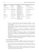
Introduction to Thermal Systems Engineering (ITSE). Also, IT has a folder with a large number of
examples from Fundamentals. Most of these examples are in ITSE as well, and the table below
shows the correspondence. Some of the IT examples are not relevant to the thermal systems
text, as noted in the table. The entire selection of examples, though, provides a complete set of
illustrations of the capabilities of IT.
IT capabilities tied to topics beyond the scope of ITSE
• Exergy analysis
• Reacting mixtures and combustion
• Chemical and phase equilibrium
IT Examples – Fundamentals and ITSE equivalence guide
Fundamentals ITSE Description
2.1 3.1 Evaluating expansion work
3.3 4.3 Stirring water at constant volume
3.5 4.5 Plotting thermodynamic data using software
4.5 5.5 Calculating compressor power
6.14 7.12 (CD-ROM) Evaluating the isentropic compressor
efficiency
8.5 8.4 Regenerative cycle with open feedwater
heater
9.6 9.4 Brayton cycle with irreversibilities
9.14 12.8 (CD-ROM) Effect of back pressure: converging nozzle
12.14 10.4 Spray-steam humidifier
13.8 Not included Determining the adiabatic flame temperature
14.6 Not included Determining the equilibrium flame
temperature
14.7 Not included Determining the equilibrium flame
temperature using software
Things You Should Know Version 1 05-31-02 Page 4 of 7
IHT: Some Special Tips
IHT was designed to accompany the text Fundamentals of Heat and Mass Transfer (4ed, 2002)
and Introduction to Heat Transfer (5ed, Wiley, 2002), and includes a number of features that will
enhance your study of heat transfer. However, many other features are beyond the scope of
coverage in ITSE, so it is not useful to track any equivalence between the two texts with respect
to topics and examples for use of the software.
It is the purpose of this section to identify specific features of IHT that will increase your
productivity in problem solving. In addition to having basic solver literacy, and good skills in
using IT as earlier described, you will find the following topics useful in solving the heat transfer
problems of ITSE.
Entering Equations from Text Reference Tables and Figures
It has been our practice in the ITSE heat transfer chapters to summarize key concepts and
equations in table or figures to facilitate convenient reference during your problem solving
sessions. You should be able to enter the relevant equations into the IHT Workspace and affect
solutions.
Table/Figure Content
T-15.5 Rate equations for conduction, convection, radiation
T-16.3 One-dimensional conduction: HE solutions, resistances
T-16.4 Fin equations: distribution, heat rates
F-16.27 Semi-infinite media: temperature distribution, heat rate
T-17.3 Correlations: external flow
T-17.5 Correlations: internal flow; also with Eq. 17.56
T-17.6 Correlations: free convection
Understanding How to Handle Stiff-Equation Sets
The solver engine affects solutions to the equation set comprising your model by using initial
guesses to converge on the values for the unknown variables. With highly non-linear equations,
the engine might not converge within the required limits for the allowed iterations. Examples of
such equations include the convection correlations, property functions, the radiation rate
equation, and the LMTD heat exchanger method.
The strategy for dealing with stiff-equations sets involves making good initial guesses and
specifying upper and lower bounds. Also, consider developing models of more complex systems
by building on simplified models. For more advice see the IHT Help, Solution Strategies and
Hints.
Things You Should Know Version 1 05-31-02 Page 5 of 7
Using Functions that Provide Unique Computational Capability
There are four heat- transfer-specific intrinsic functions that provide unique computation capability
for the problems of ITSE . A function is a subroutine that performs a calculation based upon
values of the argument provided by the user. Descriptions of the function and IHT Help
references follow. See the final section, IHT Codes for Text Examples, for the identity of the IHT
files that illustrate use of these functions.
Function / Description
DER(T,t)
Used to solve differential equations, in this case, the derivative of temperature T with respect to
time t. Useful for solving the transient energy balance of the for the lumped capacitance method,
Eq. 16.81. See Example 16.9, Comment 4. IHT Help reference: Solver, Intrinsic Functions, DER
Function.
Properties
Provides functions for the thermophysical properties of selected materials, liquids and gases.
Click on the Properties button on the Tool Bar for the substance of choice, highlight window
contents, and drag the functions into the Workspace. Properties are based on values from ITSE
Appendices HT-1 to 5. For example, the function for the thermal conductivity of air at one
atmosphere is “k = k_T(“Air”,T) // Thermal conductivity, W/m-K”. Note, the temperature T must
be specified in kelvin units. IHT Help reference: Tools, Properties.
Tfluid_avg(x,y)
Calculates the film temperature or average mean temperature for internal flow, written as
Tf = Tfluid_avg(Ts,Tinf) or Tmbar = Tfluid_avg(Tmi,Tmo)
This function is preferred to “Tf = (Ts + Tinf)/2” when working with stiff-equation sets. IHT Help
reference: Solver, Intrinsic Functions, Tfluid_avg Function.
F_lambda_T(lambda,T)
Calculates the blackbody band emission factor according to Eq. 18.10a and Table 18.2. This
function is especially useful for calculating total or band properties from their spectral
distributions. See Example 18.4, Comment 2, for an illustration of its use. IHT reference: Tools,
Radiation Exchange, Radiation Functions; see also from the tool bar menu, Tools, Radiation,
Band Emission Factor.
Things You Should Know Version 1 05-31-02 Page 6 of 7
Transient Conduction with Spatial Effects
IHT models have been developed for solving the transient conduction problem for a Plane Wall
with Convection, Sec. 16.5.2, and Radial Systems, Sec. 16.5.3. Evaluating the one-term series
analytical solution for these geometries is tedious work, requiring use of tables for the coefficients
C and ζ or Bessel functions.
The following table presents the functions that will allow you to calculate the temperature
distribution T(x,t) or T(r,t) and energy transfer relation Q/Qo for the plane wall and radial system
geometries. The functions are keyed to equations in your text. You must provide appropriate
equations for the function arguments: xstar (x/L) or rstar (r/ro), Bi, Fo, and Qo. The initial internal
energy, Qo, follows from Eq. 16.108. See the final section, IHT Codes for Text Examples, for the
identity of the IHT files that illustrate use of these functions.
The Plane Wall
T_xt = T_xt_trans("Plane Wall",xstar,Fo,Bi,Ti,Tinf) // Eq 16.104
QoverQo = Q_over_Qo_trans("Plane Wall",Fo,Bi) // Eq 16.110
Plane wall with an initial uniform temperature, Ti, subjected to sudden convection conditions (Tinf,
h) as represented in Fig. 16.25. These functions represent the multiple-term series analytical
solution, and hence will return more accurate results than the one-term solutions of the text.
These functions are used to solve the plane wall transient conduction problem of Example 16.10.
See the next section for the identity of the IHT file.
The Infinite Cylinder
T_xt = T_xt_trans("Cylinder",rstar,Fo,Bi,Ti,Tinf) // Eq 16.111
QoverQo = Q_over_Qo_trans("Cylinder",Fo,Bi) // Eq 16.113
Infinite cylinder with an initial uniform temperature, Ti, subjected to sudden convection conditions
(Tinf, h) as represented in Fig. 16.26. These functions represent the multiple-term series
analytical solution, and hence will return more accurate results than the one-term solutions of the
text.
The Sphere
T_xt = T_xt_trans("Sphere",rstar,Fo,Bi,Ti,Tinf) // Eq 16.112
QoverQo = Q_over_Qo_trans("Sphere",Fo,Bi) // Eq 16.114
Sphere with an initial uniform temperature, Ti, subjected to sudden convection conditions (Tinf, h)
as represented in Fig. 16.26. These functions represent the multiple-term series analytical
solution, and hence will return more accurate results than the one-term solutions of the text.
These functions are used to solve the sphere transient conduction problem of Example 16.11.
Things You Should Know Version 1 05-31-02 Page 7 of 7
IHT Codes for ITSE Text Examples
Six examples from ITSE have been solved using IHT. The examples were chosen to illustrate
the use of the functions described in the previous sections. The following table identifies the
features illustrated in the example, and the identity of the IHT file that is located in the directory on
your CD-ROM labeled IHT Text Example Codes. You can open one of these files while in IHT,
press the Solve button, and examine the results in the Data Browser.
Text Example / Content / File name*
16.9 Workpiece temperature-time history during heat treatment. E16_09.msm
Use of the derivative function DER(T,t) for solving the
transient energy balance including radiation exchange as
treated in Comment 4.
16.10 Plane wall experiencing sudden convective conditions. E16_10A.msm
Use of transient conduction functions T_xt_trans(“Plane Wall”,…) E16_10B.msm
and Q_over_Qo_trans(“Plane Wall”,…. ). The files –A and –B
correspond to solutions for parts a-d and Comment 2, respectively.
16.11 Quenching a spherical workpiece in an oil bath. E16_11.msm
Use of transient conduction functions T_xt_trans(“Cylinder”,…)
and Q_over_Qo_trans(“Cylinder”,…. ) to calculate quench time.
17.11 Turbulent flow: Steam-heated water supply line. E17_10.msm
Use of Tfluid_avg and Properties functions with an internal flow
convection correlation to determine outlet temperature for
constant temperature surface condition.
17.12 Free convection: Cooling an electronic equipment enclosure. E17_12.msm
Use of Tfluid_avg and Properties functions with a free convection
correlation to estimate heat flux by convection and radiation
18.4 Total emissivity from the spectral emissivity distribution. E18_04.msm
Use of the blackbody band emission function F_lambda_T(lambda,T)
to evaluate total emissivity as a function of temperature
________
* These files are located in the directory IHT Text Example Codes on your CD-ROM. When
opened from IHT, the files appear with the “.msm” extension. IHT searches for files based on this
extension, but the saved session includes three other files with the same name (up to eight
characters), but different extensions (.dsk, .eqd, and .eqs). Remember to include all four files if
you perform a copy-and-paste sequence to relocate the files from your CD-ROM to another drive
on your computer.
1
Introduction…
The objective of this chapter is to introduce you to thermal systems engineering
using several contemporary applications. Our discussions use certain terms that
we assume are familiar from your background in physics and chemistry. The
roles of thermodynamics, fluid mechanics, and heat transfer in thermal systems
engineering and their relationship to one another also are described. The
presentation concludes with tips on the effective use of the book.
Getting Started
Thermal systems engineering is concerned with how energy is utilized to accomplish bene-
ficial functions in industry, transportation, and the home, and also the role energy plays in
the study of human, animal, and plant life. In industry, thermal systems are found in electric
power generating plants, chemical processing plants, and in manufacturing facilities. Our
transportation needs are met by various types of engines, power converters, and cooling equip-
ment. In the home, appliances such as ovens, refrigerators, and furnaces represent thermal
systems. Ice rinks, snow-making machines, and other recreational uses involve thermal sys-
tems. In living things, the respiratory and circulatory systems are thermal systems, as are
equipment for life support and surgical procedures.
Thermal systems involve the storage, transfer, and conversion of energy. Energy can be
stored within a system in different forms, such as kinetic energy and gravitational potential
energy. Energy also can be stored within the matter making up the system. Energy can be
transferred between a system and its surroundings by work, heat transfer, and the flow of
hot or cold streams of matter. Energy also can be converted from one form to another. For
example, energy stored in the chemical bonds of fuels can be converted to electrical or me-
chanical power in fuel cells and internal combustion engines.
The sunflowers shown on the cover of this book can be thought of as thermal systems.
Solar energy aids the production of chemical substances within the plant required for life
(photosynthesis). Plants also draw in water and nutrients through their root system. Plants
interact with their environments in other ways as well.
Selected areas of application that involve the engineering of thermal systems are listed
in Fig. 1.1, along with six specific illustrations. The turbojet engine, jet ski, and electrical
power plant represent thermal systems involving conversion of energy in fossil fuels to
achieve a desired outcome. Components of these systems also involve work and heat trans-
fer. For life support on the International Space Station, solar energy is converted to electrical
energy and provides energy for plant growth experimentation and other purposes. Semi-
conductor manufacturing processes such as high temperature annealing of silicon wafers
involve energy conversion and significant heat transfer effects. The human cardiovascular
1.1
chapter objective
WHAT IS THERMAL SYSTEMS
ENGINEERING?
1
c01.qxd 7/9/02 13:47 Page 1
2 Chapter 1. What Is Thermal Systems Engineering?
Coal Air
Condensate
Cooling water
Ash
Stack
Steam generator
Condenser
Generator
Cooling
tower
Electric
power
Electrical power plant
Combustion
gas cleanup
Turbine
Steam
Turbojet engine
Solar-cell arrays
Compressor
Turbine
Air in
Hot gases
out
Combustor
Fuel in
Thorax
Quartz-tube furnace
Lung
Heart
Surfaces with thermal
control coatings
International Space Station
Jet ski water =-pump propulsion
Human cardiovascular system
Wafer boat
High-temperature annealing of silicon wafers
3.5 in. diameter
outlet jet
30°
25 in.
2
inlet area
Figure 1.1 Selected areas of applications for thermal systems engineering.
Prime movers: internal-combustion engines, turbines
Fluid machinery: pumps, compressors
Fossil- and nuclear-fueled power stations
Alternative energy systems
Fuel cells
Solar heating, cooling and power generation
Heating, ventilating, and air-conditioning equipment
Biomedical applications
Life support and surgical equipment
Artificial organs
Air and water pollution control equipment
Aerodynamics: airplanes, automobiles, buildings
Pipe flow: distribution networks, chemical plants
Cooling of electronic equipment
Materials processing: metals, plastics, semiconductors
Manufacturing: machining, joining, laser cutting
Thermal control of spacecraft
c01.qxd 7/9/02 13:47 Page 2
1.2 Thermal System Case Studies 3
system is a complex combination of fluid flow and heat transfer components that regulates
the flow of blood and air to within the relatively narrow range of conditions required to
maintain life.
In the next section, three case studies are discussed that bring out important features of
thermal systems engineering. The case studies also suggest the breadth of this field.
Thermal System Case Studies
Three cases are now considered to provide you with background for your study of thermal
systems engineering. In each case, the message is the same: Thermal systems typically con-
sist of a combination of components that function together as a whole. The components
themselves and the overall system can be analyzed using principles drawn from three dis-
ciplines: thermodynamics, fluid mechanics, and heat transfer. The nature of an analysis
depends on what needs to be understood to evaluate system performance or to design or
upgrade a system. Engineers who perform such work need to learn thermal systems prin-
ciples and how they are applied in different situations.
1.2.1 Domestic Hot Water Supply
The installation that provides hot water for your shower is an everyday example of a ther-
mal system. As illustrated schematically in Fig. 1.2a, a typical system includes:
•
a water supply
•
a hot-water heater
•
hot-water and cold-water delivery pipes
•
a faucet and a shower head
The function of the system is to deliver a water stream with the desired flow rate and tem-
perature.
Clearly the temperature of the water changes from when it enters your house until it
exits the shower head. Cold water enters from the supply pipe with a pressure greater than
the atmosphere, at low velocity and an elevation below ground level. Water exits the shower
head at atmospheric pressure, with higher velocity and elevation, and it is comfortably hot.
The increase in temperature from inlet to outlet depends on energy added to the water by
heating elements (electrical or gas) in the hot water heater. The energy added can be eval-
uated using principles from thermodynamics and heat transfer. The relationships among
the values of pressure, velocity, and elevation are affected by the pipe sizes, pipe lengths,
and the types of fittings used. Such relationships can be evaluated using fluid mechanics
principles.
Water heaters are designed to achieve appropriate heat transfer characteristics so that the
energy supplied is transferred to the water in the tank rather than lost to the surrounding air.
The hot water also must be maintained at the desired temperature, ready to be used on de-
mand. Accordingly, appropriate insulation on the tank is required to reduce energy losses to
the surroundings. Also required is a thermostat to call for further heating when necessary.
When there are long lengths of pipe between the hot water heater and the shower head, it
also may be advantageous to insulate the pipes.
The flow from the supply pipe to the shower head involves several fluid mechanics prin-
ciples. The pipe diameter must be sized to provide the proper flow rate—too small a diam-
eter and there will not be enough water for a comfortable shower; too large a diameter and
the material costs will be too high. The flow rate also depends on the length of the pipes and
1.2
c01.qxd 7/9/02 13:47 Page 3
4 Chapter 1. What Is Thermal Systems Engineering?
the number of valves, elbows, and other fittings required. As shown in Fig. 1.2b, the faucet
and the shower head must be designed to provide the desired flow rate while mixing hot and
cold water appropriately.
From this example we see some important ideas relating to the analysis and design of
thermal systems. The everyday system that delivers hot water for your shower is composed
of various components. Yet their individual features and the way they work together as a
whole involve a broad spectrum of thermodynamics, fluid mechanics, and heat transfer prin-
ciples.
1.2.2 Hybrid Electric Vehicle
Automobile manufacturers are producing hybrid cars that utilize two or more sources of
power within a single vehicle to achieve fuel economy up to 60–70 miles per gallon.
Illustrated in Fig. 1.3a is a hybrid electric vehicle (HEV) that combines a gasoline-fueled
engine with a set of batteries that power an electric motor. The gasoline engine and the elec-
tric motor are each connected to the transmission and are capable of running the car by
themselves or in combination depending on which is more effective in powering the vehicle.
What makes this type of hybrid particularly fuel efficient is the inclusion of several features
in the design:
•
the ability to recover energy during braking and to store it in the electric batteries,
•
the ability to shut off the gasoline engine when stopped in traffic and meet power
needs by the battery alone,
•
special design to reduce aerodynamic drag and the use of tires that have very low
rolling resistance (friction), and
•
the use of lightweight composite materials such as carbon fiber and the increased use
of lightweight metals such as aluminum and magnesium.
Figure 1.2
Home hot water supply. (a) Overview. (b) Faucet and shower head.
Diverter valve
Hot
Cold
Water
heater
Cold water
supply line
Shower head
Shower head
To shower
head
Cold
water
Valve
stem
To tub
spout
Tub spout
Hot
water
Hot water
faucet
Cold water
faucet
(a)(b)
c01.qxd 7/9/02 13:47 Page 4
1.2 Thermal System Case Studies 5
The energy source for such hybrid vehicles is gasoline burned in the engine. Because of
the ability to store energy in the batteries and use that energy to run the electric motor, the
gasoline engine does not have to operate continuously. Some HEVs use only the electric
motor to accelerate from rest up to about 15 miles per hour, and then switch to the gasoline
engine. A specially designed transmission provides the optimal power split between the gaso-
line engine and the electric motor to keep the fuel use to a minimum and still provide the
needed power.
Most HEVs use regenerative braking, as shown in Fig. 1.3b. In conventional cars, step-
ping on the brakes to slow down or stop dissipates the kinetic energy of motion through
the frictional action of the brake. Starting again requires fuel to re-establish the kinetic
energy of the vehicle. The hybrid car allows some of the kinetic energy to be converted
during braking to electricity that is stored in the batteries. This is accomplished by the
electric motor serving as a generator during the braking process. The net result is a
significant improvement in fuel economy and the ability to use a smaller-sized gasoline
engine than would be possible to achieve comparable performance in a conventional
vehicle.
The overall energy notions considered thus far are important aspects of thermodynam-
ics, which deals with energy conversion, energy accounting, and the limitations on how en-
ergy is converted from one form to another. In addition, there are numerous examples of
fluid mechanics and heat transfer applications in a hybrid vehicle. Within the engine, air,
Figure 1.3
Hybrid electric vehicle combining gasoline-fueled engine, storage batteries, and
electric motor. (Illustrations by George Retseck.)
Generator
Inverter
Gasoline engine
Batteries
Electric motor
(a) Overview of the vehicle showing key thermal systems
(b) Regenerative braking mode with energy flow from wheels to battery
c01.qxd 7/9/02 13:47 Page 5
6 Chapter 1. What Is Thermal Systems Engineering?
fuel, engine coolant, and oil are circulated through passageways, hoses, ducts, and mani-
folds. These must be designed to ensure that adequate flow is obtained. The fuel pump and
water pump also must be designed to achieve the desired fluid flows. Heat transfer princi-
ples guide the design of the cooling system, the braking system, the lubrication system, and
numerous other aspects of the vehicle. Coolant circulating through passageways in the engine
block must absorb energy transferred from hot combustion gases to the cylinder surfaces so
those surfaces do not become too hot. Engine oil and other viscous fluids in the transmis-
sion and braking systems also can reach high temperatures and thus must be carefully
managed.
Hybrid electric vehicles provide examples of complex thermal systems. As in the case of
hot water systems, the principles of thermodynamics, fluid mechanics, and heat transfer ap-
ply to the analysis and design of individual parts, components, and to the entire vehicle.
1.2.3 Microelectronics Manufacturing: Soldering Printed-Circuit Boards
Printed-circuit boards (PCBs) found in computers, cell phones, and many other products, are
composed of integrated circuits and electronic devices mounted on epoxy-filled fiberglass
boards. The boards have been metallized to provide interconnections, as illustrated in
Fig. 1.4a. The pins of the integrated circuits and electronic devices are fitted into holes, and
a droplet of powdered solder and flux in paste form is applied to the pin-pad region, Fig. 1.4b.
To achieve reliable mechanical and electrical connections, the PCB is heated in an oven to
a temperature above the solder melting temperature; this is known as the reflow process. The
(b)
Integrated circuit (IC)
Pin lead
Metal film
Pre-form solder paste
(a)
(d)
(c)
Figure 1.4 Soldering printed-circuit boards (a) with pre-form solder paste applied to integrated
circuit pins and terminal pads (b) enter the solder-reflow oven (c) on a conveyor and are heated to
the solder melting temperature by impinging hot air jets (d ).
c01.qxd 7/9/02 13:47 Page 6
1.3 Analysis of Thermal Systems 7
PCB and its components must be gradually and uniformly heated to avoid inducing thermal
stresses and localized overheating. The PCB is then cooled to near-room temperature for
subsequent safe handling.
The PCB prepared for soldering is placed on a conveyor belt and enters the first zone
within the solder reflow oven, Fig. 1.4c. In passing through this zone, the temperature of the
PCB is increased by exposure to hot air jets heated by electrical resistance elements, Fig. 1.4d.
In the final zone of the oven, the PCB passes through a cooling section where its tempera-
ture is reduced by exposure to air that has been cooled by passing through a water-cooled
heat exchanger.
From the foregoing discussion, we recognize that there are many aspects of this manu-
facturing process that involve electric power, flow of fluids, air-handling equipment, heat
transfer, and thermal aspects of material behavior. In thermal systems engineering, we per-
form analyses on systems such as the solder-reflow oven to evaluate system performance or
to design or upgrade the system. For example, suppose you were the operations manager of
a factory concerned with providing electrical power and chilled water for an oven that a ven-
dor claims will meet your requirements. What information would you ask of the vendor? Or,
suppose you were the oven designer seeking to maximize the production of PCBs. You might
be interested in determining what air flow patterns and heating element arrangements would
allow the fastest flow of product through the oven while maintaining necessary uniformity
of heating. How would you approach obtaining such information? Through your study of
thermodynamics, fluid mechanics, and heat transfer you will learn how to deal with ques-
tions such as these.
Analysis of Thermal Systems
In this section, we introduce the basic laws that govern the analysis of thermal systems of
all kinds, including the three cases considered in Sec. 1.2. We also consider further the roles
of thermodynamics, fluid mechanics, and heat transfer in thermal systems engineering and
their relationship to one another.
Important engineering functions are to design and analyze things intended to meet human
needs. Engineering design is a decision-making process in which principles drawn from
engineering and other fields such as economics and statistics are applied to devise a system,
system component, or process. Fundamental elements of design include establishing
objectives, analysis, synthesis, construction, testing, and evaluation.
Engineering analysis frequently aims at developing an engineering model to obtain a
simplified mathematical representation of system behavior that is sufficiently faithful to
reality, even if some aspects exhibited by the actual system are not considered. For ex-
ample, idealizations often used in mechanics to simplify an analysis include the assump-
tions of point masses, frictionless pulleys, and rigid beams. Satisfactory modeling takes
experience and is a part of the art of engineering. Engineering analysis is featured in this
book.
The first step in analysis is the identification of the system and how it interacts with its
surroundings. Attention then turns to the pertinent physical laws and relationships that allow
system behavior to be described. Analysis of thermal systems uses, directly or indirectly, one
or more of four basic laws:
•
Conservation of mass
•
Conservation of energy
•
Conservation of momentum
•
Second law of thermodynamics
1.3
c01.qxd 7/9/02 13:47 Page 7
8 Chapter 1. What Is Thermal Systems Engineering?
In your earlier studies in physics and chemistry, you were introduced to these laws. In
this book, we place the laws in forms especially well suited for use in thermal systems
engineering and help you learn how to apply them.
1.3.1 The Three Thermal Science Disciplines
As we have observed, thermal systems engineering typically requires the use of three ther-
mal science disciplines: thermodynamics, fluid mechanics, and heat transfer. Figure 1.5 shows
the roles of these disciplines in thermal system engineering and their relationship to one
another. Associated with each discipline is a list of principles featured in the part of the book
devoted to that discipline.
Thermodynamics provides the foundation for analysis of thermal systems through the con-
servation of mass and conservation of energy principles, the second law of thermodynamics,
and property relations. Fluid mechanics and heat transfer provide additional concepts, in-
cluding the empirical laws necessary to specify, for instance, material choices, component
sizing, and fluid medium characteristics. For example, thermodynamic analysis can tell you
the final temperature of a hot workpiece quenched in an oil, but the rate at which it will cool
is predicted using a heat transfer analysis.
Fluid mechanics is concerned with the behavior of fluids at rest or in motion. As shown
in Fig. 1.5, two fundamentals that play central roles in our discussion of fluid mechanics are
the conservation of momentum principle that stems from Newton’s second law of motion and
the mechanical energy equation. Principles of fluid mechanics allow the study of fluids flowing
inside pipes (internal flows) and over surfaces (external flows) with consideration of frictional
Thermal Systems Engineering
Analysis directed to
Design
Operations/Maintenance
Marketing/Sales
Costing
•
•
•
Conservation of mass
Conservation of energy
Second law of thermodynamics
Properties
Thermodynamics
Fluid Mechanics
Fluid statics
Conservation of momentum
Mechanical energy equation
Similitude and modeling
Heat Transfer
Conduction
Convection
Radiation
Multiple Modes
F
l
u
i
d
s
H
e
a
t
t
r
a
n
s
f
e
r
T
h
e
r
m
o
Figure 1.5 The disciplines of thermodynamics, fluid mechanics, and heat transfer involve
fundamentals and principles essential for the practice of thermal systems engineering.
c01.qxd 7/9/02 13:47 Page 8
1.4 How to Use This Book Effectively 9
effects and lift/drag forces. The concept of similitude is used extensively in scaling measure-
ments on laboratory-sized models to full-scale systems.
Heat transfer is concerned with energy transfer as a consequence of a temperature dif-
ference. As shown in Fig. 1.5, there are three modes of heat transfer. Conduction refers
to heat transfer through a medium across which a temperature difference exists. Convection
refers to heat transfer between a surface and a moving or still fluid having a different
temperature. The third mode of heat transfer is termed thermal radiation and represents
the net exchange of energy between surfaces at different temperatures by electromagnetic
waves independent of any intervening medium. For these modes, the heat transfer rates
depend on the transport properties of substances, geometrical parameters, and tempera-
tures. Many applications involve more than one of these modes; this is called multimode
heat transfer.
Returning again to Fig. 1.5, in the thermal systems engineering box we have identified
some application areas involving analysis. Earlier we mentioned that design requires analy-
sis. Engineers also perform analysis for many other reasons, as for example in the operation
of systems and determining when systems require maintenance. Because of the complexity
of many thermal systems, engineers who provide marketing and sales services need analy-
sis skills to determine whether their product will meet a customer’s specifications. As engi-
neers, we are always challenged to optimize the use of financial resources, which frequently
requires costing analyses to justify our recommendations.
1.3.2 The Practice of Thermal Systems Engineering
Seldom do practical applications involve only one aspect of the three thermal sciences disci-
plines. Practicing engineers usually are required to combine the basic concepts, laws, and prin-
ciples. Accordingly, as you proceed through this text, you should recognize that thermodynamics,
fluid mechanics, and heat transfer provide powerful analysis tools that are complementary.
Thermal systems engineering is interdisciplinary in nature, not only for this reason, but because
of ties to other important issues such as controls, manufacturing, vibration, and materials that
are likely to be present in real-world situations.
Thermal systems engineering not only has played an important role in the development
of a wide range of products and services that touch our lives daily, it also has become an
enabling technology for evolving fields such as nanotechnology, biotechnology, food pro-
cessing, health services, and bioengineering. This textbook will prepare you to work in both
traditional and emerging energy-related fields.
Your background should enable you to
•
contribute to teams working on thermal systems applications.
•
specify equipment to meet prescribed needs.
•
implement energy policy.
•
perform economic assessments involving energy.
•
manage technical operations.
This textbook also will prepare you for further study in thermodynamics, fluid mechanics,
and heat transfer to strengthen your understanding of fundamentals and to acquire more
experience in model building and solving applications-driven problems.
How to Use This Book Effectively
This book has several features and learning resources that facilitate study and contribute
further to understanding.
1.4
c01.qxd 7/9/02 13:47 Page 9
10 Chapter 1. What Is Thermal Systems Engineering?
ETHODOLOGY
UPDATE
M
Core Study Features
Examples and Problems . . .
•
Numerous annotated solved examples are provided that feature the solution
methodology presented in Sec. 2.6, and illustrated initially in Example 2.1. We
encourage you to study these examples, including the accompanying comments.
•
Less formal examples are given throughout the text. They open with the words For
Example… and close with the symbol ▲. These examples also should be studied.
•
A large number of end-of-chapter problems are provided. The problems are se-
quenced to coordinate with the subject matter and are listed in increasing order of
difficulty. The problems are classified under headings to expedite the process of
selecting review problems to solve.
Other Study Aids . . .
•
Each chapter begins with an introduction stating the chapter objective and con-
cludes with a summary and study guide.
•
Key words are listed in the margins and coordinated with the text material at those
locations.
•
Key equations are set off by a double horizontal bar.
•
Methodology Update in the margin identifies where we refine our problem-solving
methodology, introduce conventions, or sharpen our understanding of specific
concepts.
•
For quick reference, conversion factors and important constants are provided on
the inside front cover and facing page.
•
A list of symbols is provided on the inside back cover and facing page.
•
(CD-ROM) directs you to the accompanying CD where supplemental text material
and learning resources are provided.
Icons . . .
identifies locations where the use of appropriate computer software is
recommended.
directs you to short fluid mechanics video segments.
Enhanced Study Features
Computer Software . . .
To allow you to retrieve appropriate data electronically and model and solve complex ther-
mal engineering problems, instructional material and computer-type problems are pro-
vided on the CD for Interactive Thermodynamics (IT) and Interactive Heat Transfer (IHT).
These programs are built around equation solvers enhanced with property data and other
valuable features. With the IT and IHT software you can obtain a single numerical solu-
tion or vary parameters to investigate their effects. You also can obtain graphical output,
and the Windows-based format allows you to use any Windows word-processing software
or spreadsheet to generate reports. Tutorials are available from the ‘Help’ menu, and both
programs include several worked examples.
Accompanying CD . . .
The CD contains the entire print version of the book plus the following additional con-
tent and resources:
•
answers to selected end-of-chapter problems
•
additional text material not included in the print version of the book
c01.qxd 7/9/02 13:47 Page 10