Masters thesis of applied science (medical and health physics) characterisation of dosimetry in electron radiotherapy under different bolus applications
Bạn đang xem bản rút gọn của tài liệu. Xem và tải ngay bản đầy đủ của tài liệu tại đây (6.76 MB, 238 trang )
Characterisation of Dosimetry in Electron
Radiotherapy under different Bolus Applications.
Lindsay James Tremethick
BApp.Sc. (University of South Australia)
A thesis submitted in partial fulfilment of the requirements for the degree of
Master of Applied Science (Medical and Health Physics)
School of Applied Sciences,
College of Science, Engineering and Health
RMIT University
Melbourne, Australia
March 2012
Page i
Declaration
Except where acknowledgements are made in the text, all work described in this thesis is that
of the author.
This thesis has not previously been submitted in whole or in part for any academic award to
any Institute or University.
The content of this thesis is the result of work carried out since the official commencement
date of the approved research program.
Lindsay J. Tremethick
Page ii
Acknowledgement
The following thesis would not have been completed if not for the support and constant
encouragement of many others.
I would like to thank my many supervisors for what may have been one of your most
frustrating students. Firstly Jamie Trapp for listening to my generalised thoughts and ideas of
a possible Masters topic and believing them suitable, starting me along what has been a long
and at times almost torturous path.
The departure of Jamie from RMIT lumbered Peter Johnston and Rick Franich with me as an
additional student to their already full student supervision lists. Despite what must have been
an imposition on their personal time they afforded me unconditional support whenever I
requested assistance.
Peter Johnston's departure from RMIT landed me squarely and solely on Rick Franich's now
excessively bloated student supervision list. I certainly appreciated Rick's continued support
and also the provision of appropriate advice when for personal reasons I opted to exercise an
initial period of Leave of Absence which became extended through unavoidable
circumstances. It was only through Rick's tireless efforts that my forced extended Leave of
Absence, and what was then an “in limbo” Masters programme, was resurrected by his
approach to Moshi Geso to act as my supervisor. Without Moshi's generous acceptance of me
as a student and the provision of his time, often at my request, along with his advice and
direction my thesis may not have commenced.
I also wish to thank my employer Radiation Oncology Victoria (now part of GenesisCare) and
in particular Bill Patterson for the constant support provided in both time and resources. Bill
has provided many hours of his personal time both proof reading my writings and supporting
my efforts. Bill's constant reminders of the ultimate deadline, his time spent listening to, and
providing suggestions for my, at times, hair brained ideas, and his assistance with some of my
day to day duties has aided me immensely to complete the thesis.
Finally I must thank my wife and children for putting up with me during the course of this
Page iii
Masters particularly in the last year. I know at times I must have been like a “bear with a sore
head”.
To my wife Anne, who must have been bored to almost tears reading many drafts of my
writings and repeatedly corrected the same grammatical errors plus finding those spelling
errors a word processor never does, I owe you many thanks. To my boys Samuel and Edward
that is the end of study for me!
Page iv
Table of Contents
Declaration............................................................................................................ii
Acknowledgement................................................................................................iii
Illustration Index.................................................................................................vii
Index of Tables......................................................................................................x
0. ABSTRACT......................................................................................................1
1. INTRODUCTION.............................................................................................2
1.1 Radiotherapy....................................................................................................................2
1.2 Electron Interactions.........................................................................................................7
1.2.1 Stopping Powers.......................................................................................................8
1.3 Electron Beam Therapy .................................................................................................11
1.4 Modulated Electron Radiotherapy..................................................................................12
1.5 Aims................................................................................................................................14
2 METHODOLOGICAL DESIGN.....................................................................15
2.1 Equipment & General Data Collection Conditions........................................................15
2.2 Clinical Electron Beam Characteristics..........................................................................19
2.2.1 Central Axis Percentage Depth Dose......................................................................22
2.2.1.1 PDD Dependence on Energy..........................................................................23
2.2.1.2 PDD Dependence on Field Size......................................................................25
2.2.1.3 PDD Dependence on Angle of incidence........................................................25
2.3 Ionisation Chambers.......................................................................................................27
2.3.1 Thimble Chambers..................................................................................................29
2.3.2 Parallel Plate Chambers..........................................................................................30
2.4 Data Collection...............................................................................................................32
2.4.1 Depth Ionisation to Depth Dose Conversion..........................................................34
2.5 Specific Measurement Conditions..................................................................................35
2.5.1 Effective Point of Measurement (EPOM)..............................................................37
2.6 Bolus Materials...............................................................................................................40
2.7 Smoothing Algorithms...................................................................................................44
3. RESULTS........................................................................................................46
3.1 Beam Quality Comparison.............................................................................................47
3.2 Spatial resolution as a function of chamber IC-15, CC-04 and PPC-40(Roos Type)....48
3.3 Bolus on the Applicator..................................................................................................51
3.3.1 Full Bolus...............................................................................................................53
3.3.1.1 Full Bolus Perspex..........................................................................................54
3.3.1.2 Full Bolus Teflon...........................................................................................56
3.3.1.3 Full Bolus Aluminium.....................................................................................58
3.3.2 Partial Bolus...........................................................................................................60
3.3.2.1 Partial Bolus Perspex......................................................................................61
3.3.2.2 Partial Bolus Teflon........................................................................................63
3.3.2.3 Partial Bolus Aluminium.................................................................................65
3.3.3 Strip Bolus..............................................................................................................67
Page v
3.3.3.1 Strip Bolus Teflon...........................................................................................68
3.3.4 Higher Z Grids........................................................................................................70
3.3.4.1 Aluminium Mesh............................................................................................71
3.3.4.2 Stainless Steel Mesh.......................................................................................73
3.4 Bolus on Surface............................................................................................................75
3.4.1 Perspex....................................................................................................................76
3.4.2 Teflon......................................................................................................................77
4. DISCUSSION..................................................................................................78
4.1 Beam Quality..................................................................................................................78
4.3 Bolus on Applicator........................................................................................................80
4.3.1 Full Bolus...............................................................................................................80
4.3.2 Partial Bolus...........................................................................................................83
4.3.3 Strip Bolus..............................................................................................................85
4.3.4 Higher Z Grids........................................................................................................86
4.4 Bolus on Surface............................................................................................................88
5. CONCLUSION...............................................................................................90
6. BIBLIOGRAPHY...........................................................................................91
APPENDIX.......................................................................................................100
Page vi
Illustration Index
Illustration 1: Electron Interactions a) excitation, b) ionisation, c) bremsstrahlung, d) characteristic
radiation production (Khan, 1991)..........................................................................................................7
Illustration 2: Stopping Power – Collisional/Radiative
(physics.nist.gov/PhysRefData/Star/Text/ESTAR.html).........................................................................9
Illustration 3: Depth–dose curves in water for electron beams,(solid curves), cf depth–dose curves for5
MV (small-dashed line) and 22 MV (long-dashed line) x-ray beams (Farmer, 1962, Hogstrom and
Almond, 2006)......................................................................................................................................11
Illustration 4: Varian 21EX Linac (Image courtesy of Varian Medical Systems, Inc. All rights
reserved.)..............................................................................................................................................15
Illustration 5: 3D Blue Phantom, “water tank” (Wellhöfer, IBA Dosimetry, Germany)........................16
Illustration 6: Linac Axis (Emma Viviers - www.medphysfile.com)....................................................17
Illustration 7: 9MeV 10x10cm Field Size (Podgorsak, 2005)...............................................................20
Illustration 8: 20 MeV 10x10 cm Field (Podgorsak, 2005)...................................................................20
Illustration 9: Electron PDD Curve (Podgorsak, 2005)........................................................................21
Illustration 10: PDD: 6MV photon, 8MeV electron .............................................................................22
Illustration 11: PDI Electron beams Field Size 15x15cm.....................................................................23
Illustration 12: PDD 20MeV by Field Size (Podgorsak, 2005).............................................................25
Illustration 13: PDD at various beam angles (a) 9MeV (b) 15MeV (Podgorsak, 2005)........................26
Illustration 14: Simplified Ionisation Chamber (Wikipedia).................................................................27
Illustration 15: Farmer Chamber (Podgorsak, 2005).............................................................................29
Illustration 16: Parallel Plate Chamber (IAEA)....................................................................................31
Illustration 17: IC-15 (CC-13) Compact Ionisation Chamber (Wellhöfer IBA Dosimetry Germany)...32
Illustration 18: CC-04 Compact Ionisation Chamber (Wellhöfer, IBA Dosimetry, Germany)..............33
Illustration 19: Water Surface Alignment..............................................................................................36
Illustration 20: CC-04 Chamber Dimensions........................................................................................39
Illustration 21: Image of Varian electron applicator and insert (maestro-research.org).........................51
Illustration 22: Full Bolus on LMA insert Set up..................................................................................53
Illustration 23: Partial Bolus on LMA insert Set up..............................................................................60
Illustration 24: Example Inplane Scan from raw data...........................................................................60
Illustration 25: Strip Bolus on LMA insert Set up.................................................................................67
Illustration 26: Example inplane scan from raw data............................................................................67
Illustration 27: Mesh (grid) Bolus on LMA insert Set up.....................................................................70
Illustration 28: 9MeV Thesis and Commissioning Depth Ionisation for Table 7..............................102
Illustration 29: 20MeV Thesis and Commissioning Depth Ionisation PDI for Table 7......................103
Illustration 30: 6MeV Roos and CC-04 Chamber Depth Ionisation Table 8......................................105
Illustration 31: 9MeV Roos, CC-04 & IC-15(green) Chamber Depth Ionisation Table 8...................106
Illustration 32: 12MeV Roos and CC-04 Chamber Depth Ionisation Table 8.....................................107
Illustration 33: 16MeV Roos and CC-04 Chamber Depth Ionisation Table 8.....................................108
Illustration 34: 20MeV Roos, CC-04 & IC-15(green) Depth Ionisation Chamber Table 8.................109
Illustration 35: 9MeV Inplane-Net 15x15cm field size CC-04............................................................111
Illustration 36: 9MeV Inplane-Net 15x15cm field size IC-15.............................................................112
Illustration 37: 20MeV Inplane-Net 15x15cm field size CC-04.........................................................113
Illustration 38: 20MeV Inplane-Net 15x15cm field size IC-15...........................................................114
Illustration 39: 9MeV Isodose Overlay IC-15 (solid) CC-04 (dotted).................................................115
Illustration 40: 20MeV Isodose Overlay IC-15 (solid) CC-04 (dotted)...............................................116
Illustration 41: Full Bolus on Applicator Depth Ionisation- Perspex 9MeV from Table 11 ................118
Illustration 42: Full Bolus on Applicator Depth Ionisation- Perspex 20MeV from Table 12...............119
Illustration 43: 9MeV Open Field for Table 13...................................................................................120
Illustration 44: Full Bolus 9MeV 1x6mm Perspex for Table 13.........................................................121
Illustration 45: Full Bolus 9MeV 2x6mm Perspex for Table 13.........................................................122
Illustration 46: Full Bolus 9MeV 3x6mm Perspex for Table 13.........................................................123
Page vii
Illustration 47: 6MeV Open Field Table 13........................................................................................124
Illustration 48: 20MeV Open Field Table 13......................................................................................125
Illustration 49: Full Bolus 20MeV 1x6mm Perspex for Table 13.......................................................126
Illustration 50: Full Bolus 20MeV 2x6mm Perspex for Table 13.......................................................127
Illustration 51: Full Bolus 20MeV 3x6mm Perspex for Table 13.......................................................128
Illustration 52: 16MeV Open Field Table 13......................................................................................129
Illustration 53: Full Bolus on Applicator Depth Ionisation - Teflon 9MeV from Table 15..................131
Illustration 54: Full Bolus on Applicator Depth Ionisation -Teflon 20MeV from Table 16.................132
Illustration 55: Full Bolus 9MeV 1x3mm Teflon for Table 17............................................................133
Illustration 56: Full Bolus 9MeV 2x3mm Teflon for Table 17............................................................134
Illustration 57: Full Bolus 20MeV 1x3mm Teflon for Table 17..........................................................135
Illustration 58: Full Bolus 20MeV 2x3mm Teflon for Table 17..........................................................136
Illustration 59: Full Bolus on Applicator Depth Ionisation - Aluminium 9MeV from Table 19..........138
Illustration 60: Full Bolus on Applicator Depth Ionisation - Aluminium 20MeV from Table 20........139
Illustration 61: Full Bolus 9MeV 2.5mm Aluminium for Table 21.....................................................140
Illustration 62: Full Bolus 9MeV 5.0mm Aluminium for Table 21.....................................................141
Illustration 63: Full Bolus 20MeV 2.5mm Aluminium for Table 21...................................................142
Illustration 64: Full Bolus 20MeV 5.0mm Aluminium for Table 21...................................................143
Illustration 65: Partial Bolus Perspex Depth Ionisation - Central Axis – 9MeV from Table 23..........145
Illustration 66: Partial Bolus Perspex Depth Ionisation - +3.5cm inplane – 9MeV from Table 23.....146
Illustration 67: Partial Bolus Perspex Depth Ionisation - Central Axis – 20MeV from Table 24........147
Illustration 68: Partial Bolus Perspex Depth Ionisation - +3.5cm inplane – 20MeV from Table 24....148
Illustration 69: Partial Bolus 9MeV 1x6mm Perspex for Table 25......................................................149
Illustration 70: Partial Bolus 9MeV 2x6mm Perspex for Table 25......................................................150
Illustration 71: Partial Bolus 9MeV 3x6mm Perspex for Table 25......................................................151
Illustration 72: Partial Bolus 20MeV 1x6mm Perspex for Table 25....................................................152
Illustration 73: Partial Bolus 20MeV 2x6mm Perspex for Table 25....................................................153
Illustration 74: Partial Bolus 20MeV 3x6mm Perspex for Table 25....................................................154
Illustration 75: Partial Bolus Teflon Depth Ionisation - Central Axis – 9MeV from Table 28.............156
Illustration 76: Partial Bolus Teflon Depth Ionisation - +3.5cm inplane – 9MeV from Table 28........157
Illustration 77: Partial Bolus Teflon Depth Ionisation - Central Axis – 20MeV from Table 29...........158
Illustration 78: Partial Bolus Teflon Depth Ionisation - +3.5cm inplane – 20MeV from Table 29......159
Illustration 79: Partial Bolus 9MeV 1x3mm Teflon for Table 30........................................................160
Illustration 80: Partial Bolus 9MeV 2x3mm Teflon for Table 30........................................................161
Illustration 81: Partial Bolus 9MeV 2x5mm Teflon for Table 30........................................................162
Illustration 82: Partial Bolus 20MeV 1x3mm Teflon for Table 30......................................................163
Illustration 83: Partial Bolus 20MeV 2x3mm Teflon for Table 30......................................................164
Illustration 84: Partial Bolus 20MeV 2x5mm Teflon for Table 30......................................................165
Illustration 85: Partial Bolus Aluminium Depth Ionisation - Central Axis – 9MeV from Table 33.....167
Illustration 86: Partial Bolus Aluminium Depth Ionisation - +3.5cm inplane – 9MeV from Table 33 168
Illustration 87: Partial Bolus Aluminium Depth Ionisation - Central Axis – 20MeV from Table 34...169
Illustration 88: Partial Bolus Aluminium Depth Ionisation - +3.5cm inplane – 20MeV from Table 34
............................................................................................................................................................ 170
Illustration 89: Partial Bolus 9MeV 2.7mm Aluminium for Table 35.................................................171
Illustration 90: Partial Bolus 9MeV 5.1mm Aluminium for Table 35.................................................172
Illustration 91: Partial Bolus 20MeV 2.7mm Aluminium for Table 35...............................................173
Illustration 92: Partial Bolus 20MeV 5.1mm Aluminium for Table 35...............................................174
Illustration 93: Strip Bolus Teflon Depth Ionisation - Open, -4cm, CA,+4cm inplane – 9MeV from
Table 38.............................................................................................................................................. 176
Illustration 94: Strip Bolus Teflon Depth Ionisation - Open, -4cm, CA,+4cm inplane – 9MeV from
Table 39.............................................................................................................................................. 177
Illustration 95: Strip Bolus 9MeV 2x5mm Teflon for Table 40..........................................................178
Illustration 96: Strip Bolus 20MeV 2x5mm Teflon for Table 40.........................................................179
Page viii
Illustration 97: Depth Ionisation Scans Higher Z Grids 9MeV.pdf from Table 42..............................182
Illustration 98: Depth Ionisation Scans Higher Z Grids 20MeV.pdf from Table 43............................183
Illustration 99: Aluminium Mesh on Applicator 1xsheet 9MeV from Table 44..................................184
Illustration 100: Aluminium Shim on Applicator 1xsheet 9MeV from Table 44.................................185
Illustration 101: Aluminium Shim on Applicator 2xsheet 9MeV from Table 44.................................186
Illustration 102: Aluminium Mesh on Applicator 1xsheet 20MeV from Table 44..............................187
Illustration 103: Aluminium Sheet on Applicator 1xsheet 20MeV from Table 44..............................188
Illustration 104: Aluminium Sheet on Applicator 2xsheet 20MeV from Table 44..............................189
Illustration 105: Stainless Steel Mesh on Applicator Depth Ionisation 9MeV from Table 46.............190
Illustration 106: Stainless Steel Mesh on Applicator Depth Ionisation 20MeV from Table 47...........191
Illustration 107: Stainless Steel Mesh on Applicator 1xsheet 9MeV for Table 48..............................192
Illustration 108: Stainless Steel Mesh on Applicator 2xsheet 9MeV for Table 48..............................193
Illustration 109: Stainless Steel Mesh on Applicator 3xsheet 9MeV for Table 48..............................194
Illustration 110: Stainless Steel Mesh on Applicator 4xsheet 9MeV for Table 48...............................195
Illustration 111: Stainless Steel Mesh on Applicator 1xsheet 20MeV for Table 48.............................196
Illustration 112: Stainless Steel Mesh on Applicator 2xsheet 20MeV for Table 48.............................197
Illustration 113: Stainless Steel Mesh on Applicator 3xsheet 20MeV for Table 48.............................198
Illustration 114: Stainless Steel Mesh on Applicator 4xsheet 20MeV for Table 48.............................199
Illustration 115: Perspex Bolus on Surface Depth Ionisation 9MeV from Table 50............................201
Illustration 116: Perspex Bolus on Surface Net 1xSheet 9MeV for Table 51......................................202
Illustration 117: Perspex Bolus on Surface Net 2xSheet 9MeV for Table 51......................................203
Illustration 118: Perspex Bolus on Surface Net 3xSheet 9MeV for Table 51......................................204
Illustration 119: Bolus on Surface Teflon 1, 2 x5mm sheet Depth Ionisation 9MeV for Table 53......205
Illustration 120: Bolus on Surface Teflon 1, 2 x5mm sheet Depth Ionisation 20MeV for Table 54....206
Illustration 121: Full Bolus Perspex with 9MeV surface shift 0.6cm..................................................209
Illustration 122: Full Bolus Perspex with 9MeV surface shift 1.22cm................................................210
Illustration 123: Full Bolus Perspex with 9MeV surface shift 1.83cm................................................211
Illustration 124: Full Bolus Perspex with 20MeV surface shift 0.6cm................................................212
Illustration 125: Full Bolus Perspex with 20MeV surface shift 1.27cm..............................................213
Illustration 126: Full Bolus Perspex with 20MeV surface shift 1.9cm................................................214
Illustration 127: Full Bolus Teflon with 9MeV surface shift 0.6cm....................................................216
Illustration 128: Full Bolus Teflon with 9MeV surface shift 1.15cm..................................................217
Illustration 129: Full Bolus Teflon with 9MeV surface shift 1.83cm..................................................218
Illustration 130: Full Bolus Teflon with 20MeV surface shift 0.58cm................................................219
Illustration 131: Full Bolus Teflon with 20MeV surface shift 1.19cm................................................220
Illustration 132: Full Bolus Teflon with 20MeV surface shift 2.1cm..................................................221
Illustration 133: Full Bolus Aluminium with 9MeV surface shift 0.65cm..........................................223
Illustration 134: Full Bolus Aluminium with 9MeV surface shift 1.21cm..........................................224
Illustration 135: Full Bolus Aluminium with 20MeV surface shift 0.69cm........................................225
Illustration 136: Full Bolus Aluminium with 20MeV surface shift 1.32cm........................................226
Page ix
Index of Tables
Table 1: Wellhöfer, IBA Dosimetry Compact Ionisation Chambers.........................................30
Table 2: Wellhöfer, PPC-40 Roos Type PP Chamber................................................................31
Table 3: Wellhöfer Electron Effective Point of Measurement IC-15........................................38
Table 4: Perspex Water Equivalent Depths...............................................................................41
Table 5: Teflon Water Equivalent Depths.................................................................................42
Table 6: Aluminium Water Equivalent Depths.........................................................................43
Table 7: R50,ion g/cm2 R80,ion g/cm2 Project & Commissioning........................................47
Table 8: R50,ion g/cm2 & R80,ion g/cm2 for thesis chambers................................................48
Table 9: R50 g/cm2 & R80 g/cm2 for thesis chambers............................................................49
Table 10: Material used for bolus..............................................................................................52
Table 11: 9MeV Perspex full bolus on LMA insert..................................................................54
Table 12: 20MeV Perspex full bolus on LMA insert................................................................54
Table 13: File Number Depth Inplane Ionisation Nets Perspex full bolus...............................54
Table 14: Penumbra and Therapeutic Region Dose Width, Full Bolus - Perspex....................55
Table 15: 9MeV, Teflon bolus on LMA insert...........................................................................56
Table 16: 20MeV, Teflon bolus on LMA insert.........................................................................56
Table 17: Depth Inplane Ionisation Nets Teflon full bolus.......................................................56
Table 18: Penumbra and Therapeutic Region Dose Width, Full Bolus - Teflon.......................57
Table 19: 9MeV, Aluminium full bolus on LMA insert............................................................58
Table 20: 20MeV, Aluminium full bolus on LMA insert..........................................................58
Table 21: Depth Inplane Ionisation Nets Aluminium full bolus...............................................58
Table 22: Penumbra and Therapeutic Region Dose Width, Full Bolus - Aluminium...............59
Table 23: 9MeV, Perspex partial bolus on LMA insert.............................................................61
Table 24: 20MeV, Perspex partial bolus on LMA insert...........................................................61
Table 25: Depth Inplane Ionisation Nets Perspex partial bolus...............................................61
Table 26: Penumbra and Therapeautic Region Dose Width, Partial Bolus - Perspex...............62
Table 27: Penumbra and Therapeautic Region Dose Width, Partial Bolus - Perspex...............62
Table 28: 9MeV, Teflon partial bolus on LMA insert...............................................................63
Table 29: 20MeV, Teflon partial bolus on LMA insert.............................................................63
Table 30: Depth Inplane Ionisation Nets Teflon partial bolus .................................................63
Table 31: Penumbra and Therapeautic Region Dose Width, Partial Bolus - Teflon.................64
Table 32: Penumbra and Therapeautic Region Dose Width, Partial Bolus – Teflon................64
Table 33: 9MeV, Aluminium partial bolus on LMA insert.......................................................65
Table 34: 20MeV, Aluminium partial bolus on LMA insert.....................................................65
Table 35: Depth Inplane Ionisation Nets Aluminium partial bolus...........................................65
Table 36: Penumbra and Therapeautic Region Dose Width, Partial Bolus - Aluminium.........66
Table 37: Penumbra and Therapeautic Region Dose Width, Partial Bolus - Aluminium.........66
Table 38: 9MeV, Teflon strip bolus on LMA insert..................................................................68
Table 39: 20MeV, Teflon strip bolus on LMA insert................................................................68
Table 40: Depth Inplane Ionisation Nets Teflon strip bolus......................................................68
Table 41: Penumbra and Therapeautic Region Dose Width, Strip Bolus - Teflon....................69
Table 42: 9MeV Aluminium mesh bolus on LMA insert..........................................................71
Table 43: 20MeV Aluminium mesh bolus on LMA insert........................................................71
Table 44: Depth Inplane Ionisation Nets Higher Z Grid bolus.................................................71
Table 45: Penumbra and Therapeutic Region Dose Width, Full Bolus – Al Mesh/Sheet.........72
Table 46: 9MeV, Stainless Steel mesh bolus on LMA insert....................................................73
Table 47: 20MeV Stainless Steel mesh bolus on LMA insert...................................................73
Page x
Table 48: Depth Inplane Ionisation Nets Stainless Steel Mesh.................................................73
Table 49: Penumbra and Therapeutic Region Dose Width, Full Bolus – Stainless Steel Mesh
...................................................................................................................................................74
Table 50: Bolus on Surface Perspex depth ionisation 9MeV....................................................76
Table 51: Depth Inplane Ionisation Nets Perspex Full surface bolus ......................................76
Table 52: Penumbra and Therapeutic Region Dose Width, Full surface Bolus - Perspex........76
Table 53: Bolus on Surface Teflon 9MeV, ...............................................................................77
Table 54: Bolus on Surface Teflon 20MeV ..............................................................................77
Page xi
0. ABSTRACT
Radiation therapy with electron beams is a technique that continues to be used by many
clinics. The characteristic depth dose with a dose build up and rapid dose drop off beyond the
peak dose permits a lesion to be treated with a relatively uniform dose whilst sparing deeper
normal tissue.
There are three general methods employed to modulate electron beams; a)Intensity Modulated
Electron Therapy b) Segmented-field Electron Conformal Therapy, c) Bolus Electron
Conformal Therapy, which can be used to achieve one or a combination of three aims; 1) level
an irregular surface and improve dose distributions (missing tissue compensator), 2) reduce
the penetration of the electron beam in certain areas (shaping isodoses closer to the distal edge
of the target volume), 3) increase the surface dose at energies below 10MeV.
The most commonly employed method in a general radiotherapy practice to modify an
electron beam is the application of a tissue like material (bolus) to the skin surface, in the
strictest sense this is not Bolus Electron Conformal Therapy (BolusECT) but rather an
element of the method as the bolus applied usually lacks sophisticated contouring. The first
two methods mentioned are both technically and resource challenging for a general
radiotherapy clinic. Unfortunately the application of bolus does have some limitations; it is
not usually sterile and the daily application in areas where there may be ulcerated, necrotic or
haemorrhaging tissue can lead to an unhygienic situation. In addition there are times when it
is difficult to mould or reproducibly position the bolus to the particular surface irregularities
leading to suboptimal treatment delivery.
Moving the bolus to the applicator level alleviates the contact and positional reproducibility
difficulties however it does introduce new challenges in understanding how this will affect the
electron beam dosimetry for the clinical treatment. This thesis provides the reader with some
of the information necessary to understand the new challenges.
Page 1
1. INTRODUCTION
1.1 Radiotherapy
Radiotherapy, Radiation Therapy, Radiation Treatment and Radiation Oncology are all terms
used to describe the same process, which is the treatment of cancer using ionising radiation.
Ionising radiation transfers energy to the molecules of the material with which it interacts. In
biological material this can result in damage to the cell in two ways; direct or indirect.
Although the distinction between whether direct or indirect effects have occurred is not
always clear, direct action is generally associated with high Linear Energy Transfer (LET)
type particles where the ionisation event occurs in the Deoxybonucleic Acid (DNA)
(McMillan, 2003, Halperin et al., 2008). Indirect action tends to be the predominant process
accounting for approximately two thirds of the biological damage with low LET radiation e.g.
electrons (Panglossi, 2007, Halperin et al., 2008). As the cell is made up of approximately
85% water(Halperin et al., 2008)(Halperin et al., 2008). Water is ionised and extremely
reactive free radicals (water ion & hydroxyl radical) are formed which can then go on to
damage other molecules in particular Deoxyribonucleis Acid (Podgorsak, 2005, Hall and
Giaccia, 2012).
The radiation can result in a wide range of cell actions including; no effect, adaptive
responses, mutation, reproductive failure, division delay or damage which includes single
and/or double (lethal) DNA strand breaks, base and sugar damage and crosslinks between
macromolecules (Read, 1957, Alper, 1963, McMillan, 2003, Podgorsak, 2005, Halperin et al.,
2008, Hall and Giaccia, 2012).
Radiotherapy has had a history only marginally shorter than Röntgen's discovery of X-rays.
In December 1895 Wilhelm Conrad Röntgen (1845 -1923) reported to The Wurzburg Medical
Physics Society; “On a new Type of Ray; A Preliminary Communication”. News of the
discovery rapidly spread throughout Europe crossing the Atlantic to New York and Chicago
(USA) resulting in more than 1000 oral and written communications on X-rays in 1896.
Röntgen's only public demonstration of X-rays was the imaging of one of his university
colleagues, (Albert von Köllicker), hand. Röntgen made a further two communications in
1896 and 1897 which further described his observations on the properties of X-rays (Bernier,
Page 2
1995).
In 1896 Henri Becquerel (Antoine Henri Becquerel 1852 -1908) somewhat accidentally
discovered natural radioactivity. At the time Becquerel was working with uranium salts
investigating whether there was any connection between X-rays and naturally occurring
phosphorescence. Becquerel had already demonstrated exposure of photographic plates,
enveloped in black paper, to what he thought were the result of phosphorescence of his
uranium and potassium salts. He exposed his experimental set-up to several hours of sunlight
believing that the uranium absorbed sunlight and emitted X-Rays. However when he repeated
his experiment a few days later, there was a decided lack of sunlight which resulted in the
experimental device being kept mainly in a drawer. After a few days of disappointing weather
Becquerel decided to process the photographic plate expecting to only see a very faint
shadow, rather what he saw a was very clear image and he concluded that the unknown rays
existed even in darkness (Allisy, 1996).
Becquerel's discovery led to further scientific investigation. In 1898 Marie Skłodowska Curie
(1867-1934) and Pierre Curie (1859-1906), working with pitchblend from Joachimsthal in
Bohemia, which exhibited a radioactivity greater than could be explained by the Uranium
alone, presented their findings to the Academy of Sciences on the discovery of a new metal
and suggested it was called Polonium. Through further work the Curie's became aware of a
second substance, also highly radioactive and again announced their discovery however it was
not until some 45 months later that Marie Curie was able to prepare 1 decigramme of radium
chloride and later pure radium (Bernier, 1995).
Following Röntgen's discovery it was soon recognised that X-ray radiation may have an
appreciable effect on normal tissue albeit detrimental. Several reports of injuries began to
emerge although because of the latency not always attributed to the radiation. Emil H. Grubbé
in his paper to Radiology (Grubbé, 1933) reported that he believed he was the first person to
recognise that cumulative exposure to x-rays had resulted in his dermatitis. This however did
lead Grubbé to investigate the use of the radiation in the treatment of carcinoma and some 60
days after Röntgen's initial communication, therapeutically delivered radiation to two patients.
Within a few years of Röntgen's and then Becquerel's discovery, it was realised that the effects
of radiation on superficial tumours required further investigation (Williams and Thwaites,
1993). Possibly the first documented “cure” of cancer by x-rays was by Dr Thor Stenbeck of
Page 3
Stockholm in 1899 of a basel cell carcinoma on the nose of a woman (Bernier, 1995).
Progress in Radiotherapy was principally determined by the development of satisfactory
sources, the work by the Curies and improvements in the X-ray producing instruments both
aided the field however the major advances in radiotherapy only came about around the late
1930's to early 1940's. The development of the Van de Graaff (1930's) and betatron
accelerators(1940's), the later being able to accelerate electrons up to tens of MeV, were able
to produce both X-Ray radiation and also electron beams (Farmer, 1962, Hogstrom and
Almond, 2006).
In the 30's the physical properties and possible advantages of high energy electron beams for
therapeutic use had been reported. Different studies had identified a reduced surface dose
(relative to the existing superficial and orthovoltage X-rays), the relatively broad dose
maximum and rapid fall off of dose at depth, (dependent on electron energy) which suggested
possible applications in dermatology (Bernier, 1995). Although there had been some
developmental work, electrons remained with limited applications because of the low
accelerating potential (2MeV restricting their use to mainly surface lesions) and large machine
size (Karzmark, 1993, Hogstrom and Almond, 2006).
In 1934 Bill (William) Hansen returned from a brief period at MIT to Stanford University as
assistant Professor of Physics and was soon immersed in researching methods of accelerating
particles (principally electrons) up to an order of a million volts. Hansen believed that existing
static accelerators such as the Van de Graaff generator would be limited by technical problems
such as insulation. He began to explore resonant cavities along the ideas of Sloan at Berkeley,
plus with additional knowledge gained from his time at MIT, eventually developed a more
practical and efficient Sloan accelerator called a Rhumbatron by Stanford.
At a similar time a graduate student, Russell Varian, began work at Stanford with Hansen. By
1936 cities in Spain and China were being bombed by air and Russell's brother Sigurd, a pilot,
was aware of the threat of the rapidly growing German Air Force and its participation with the
Nationalists (rebels) in the Spanish Civil War. At the time Sigurd believed that the destruction
occurring in Spain may spread to the United States (US) because of the support provided by
volunteers to the Republican Government forces and Sigurd knew there was no method to
combat or even detect aeroplane raids should they be launched from Central America on cities
in the United States. Discussions between the brothers lead Russell to realise the potential of
Page 4
the Rhumbatron as a radio tube capable of producing waves suitable to be used in what is now
know as RADAR. With aid provided through Stanford University (ie. room, Bill Hansen &
faculty plus $100) a royalty agreement was established and the Varian brothers commenced
their development. Within a few months, Russell presented an idea which was evaluated by
Bill Hansen and found to be promising.
The first functioning model, built by Sigurd Varian, of the Klystron occurred in 1937. At a
similar time considerable work was being conducted in England on the development of a
circular microwave generator (magnetron). Adapting the idea of multiple resonance cavities,
from the US, lead to the development by J.T. Randall & H.A. Boot of a 0.1MW magnetron in
1939 (Ginzton et al., 1948, Ginzton et al., 1957, Ginzton and Nunan, 1985, Karzmark, 1993,
Bernier, 1995). However World War II interfered with further development of Hansen's
accelerator ideas.
In 1940 Professor Donald.W. Kerst developed the first betatron (an electron accelerator) for
basic physics research (Klevenhagen, 1993). The betatron was capable of accelerating
electrons up to tens of MeV and its therapeutic usefulness was recognised with the first
patient treatment occurring in 1948 at the University of Illinois (Klevenhagen, 1993). Whilst
the betatron had the majority of the world market in the early years around 1968 (Hogstrom
and Almond, 2006), and although considerable pioneering research had been conducted by
many researchers including K. Gund, W. Paul, F. Wachsmann and J.S. Laughlin et al (Bernier,
1995), their sheer size, limited beam output and small field size eventually drove them to
obsolescence with the emerging technology of the microwave linear accelerator (Podgorsak,
2005, Hogstrom and Almond, 2006, Khan, 2010).
Following World War II two principal groups, one in the US the other in the United Kingdom
(UK), lead by W.W. Hansen and D.D Fry respectively, began independently developing
microwave electron accelerators. The two groups progressively leapfrogged each other with
their accelerators each time achieving higher electron energies. Towards the later part of 1948
the British Ministry of Health arranged the collaboration of UK research groups for the
construction of an x-ray linac for clinical use. In 1953 the first patient was treated at the
Hammersmith Hospital with an x-ray beam from an Microwave Electron Linear Accelerator.
Various Microwave Linear Accelerator structures were constructed in these formative years of
which some built such that x-ray target could be removed and radiation treatment could be
Page 5
delivered by electrons alone allowing continued research into Electron Radiotherapy
(Ginzton and Nunan, 1985, Karzmark, 1993).
Page 6
1.2 Electron Interactions
This introduction is not meant to be a comprehensive analysis of electron interactions in
matter, rather it is intended to provide the reader with only a basic understanding of some of
the predominant physical processes that affect the penetration of electrons in matter and their
resulting effects for radiotherapy. A detailed analysis is beyond the scope of this thesis and
best provided by other authors including (Johns and Cunningham, 1983, Khan, 1991,
Klevenhagen, 1993, Khan, 2010).
Electrons and photons interact differently within tissue; a photon beam traversing tissue,
whilst attenuated, effectively looses very little energy over the distances typical for
radiotherapy. Conversely the electron looses energy in small increments (appearing as
continual loss) as it passes in tissue.
Electrons are surrounded by a Coulomb electric field and start interacting with atoms
immediately entering a material by a variety of processes. The primary interactions are
i)elastic nuclear scattering, ii)inelastic collisions with orbital electrons and iii)radiative
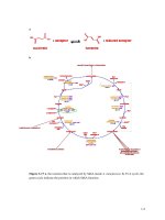
interactions with both nuclei and orbital electrons (Illustration 1).
Illustration 1: Electron Interactions a) excitation, b) ionisation, c)
bremsstrahlung, d) characteristic radiation production (Khan, 1991)
The interaction which occurs is determined by the energy of, and distance of, the incident
electron's approach to the atom or nucleus with which it interacts (Klevenhagen, 1985, Khan,
1994).
i) In elastic collisions the electron trajectory may change (scatter) or the energy may be
Page 7
redistributed among the particles emerging from the collision, however there is no kinetic
energy loss (Podgorsak, 2005).
ii) With inelastic collisions, some of the electron's kinetic energy is lost and is deposited in the
medium resulting in either an ionisation or excitation event with the collision atom. The
probability of which process occurs depends on the atomic number of the matter and the
distance and energy of the interacting electron. Generally in low atomic number matter e.g.
water or tissue, electrons tend to loose energy mainly through ionising interactions with
atomic atoms, whilst with higher atomic number matter e.g. lead, bremsstrahlung production
becomes more important (Khan, 2010). When the distance of the electron's approach is large,
relative to the dimensions of the atom, excitation occurs. Only a few eV is required to achieve
excitation and hence the energy loss by the impacting electron is very small. The excited atom
quickly returns to its stable state by emitting the excess energy in the form of visible radiation
in a gas or as heat in a solid material. If however the distance is of the order of atomic
dimensions the interaction occurs between the colliding electron and one of the atomic
electrons, stripping the orbital electron from the shell resulting in ionisation of the atom
(Klevenhagen, 1985).
Inelastic collisions are divided by the energy transferred from the impacting electron, most
frequently the energy transfer is small and the energy of the electron appears to degrade
continuously until it is captured by the material however occasionally a larger energy transfer
can occur and the ejected orbital electron “delta ray” carries off energy (> about 10keV) and
now becomes capable of causing ionisations or excitations in the same manner as described
above (Klevenhagen, 1985, Khan, 2010).
iii) Radiative interactions occur if the electrons approach is smaller than the atomic radius.
The incident electron is deflected from its incident path by the nuclear Coulomb field with the
loss of energy. The energy lost is emitted as an electromagnetic radiation known as
bremsstrahlung in a similar process as for the production of X-rays.
1.2.1 Stopping Powers
The energy transferred from the electron to the medium by collision or radiative processes is
quantified by the use of the stopping power (S). The fraction of energy loss 'dE' of an electron
per unit of path length 'dx' provides the quantity linear stopping power, i.e. S = dE/ dx (Johns
and Cunningham, 1983, Klevenhagen, 1993, Metcalfe et al., 1997). The energy lost in each
Page 8
interaction is very small which results in the appearance of the electron continuously loosing
energy and it is convenient to consider the stopping power as representing the average rate of
energy loss (Klevenhagen, 1985). In radiation dosimetry the thicknesses of materials are
usually described in mass units therefore it is advantageous to define the stopping properties
of the absorbing medium in terms of the mass stopping power. The total mass stopping power
(1/ρ)(Stot) - (defined as the quotient dE by ρdl where dE is the energy lost by a charged particle
in traversing a distance
in the medium of density ρ)(ICRU, 1980)- is given by the
relationship:
(1/ρ)Stot = (1/ρ)Srad + (1/ρ)Scoll
including the components due to radiative (Srad(ICRU, 1980)) and collisional (Scoll)
interactions.
The stopping power increases with depth as the interacting electron looses energy as it moves
further into the water. As has been noted above in Chapter:1.2 Electron Interactions the
predominant interaction in a low density medium such as water is collisional (Illustration 2 ).
Illustration 2: Stopping Power – Collisional/Radiative (physics.nist.gov/PhysRefData/Star/Text/ESTAR.html)
To determine a dose at a point in the water phantom from the depth ionisation data it is
Page 9
necessary to only consider the energy that is deposited locally therefore interactions which
result in large amounts of energy being transferred (hard collisions) to secondary electrons or
delta rays and carried away from the position can be ignored and the ionisation value is
simply multiplied by the restricted collision stopping power. Use of the unrestricted collision
stopping power would result in an overestimation of the dose deposited at the location (see
further discussion Page 27 Chapter:2.3 Ionisation Chambers).
Page 10
1.3 Electron Beam Therapy
The most clinically useful therapeutic electron beams are in the range 6-20MeV. At energies
beyond 20MeV there is less of a characteristic dose drop off and the beams start to exhibit
properties similar to photon beams (Illustration 3). Within the range, the electrons can be used
to treat superficial tumours to depths of approximately 5-6cm and still exhibit a rapid dose fall
off at depths beyond the tumour. Whilst it may be possible to treat these shallow lesions with
other modalities such as brachytherapy, superficial or tangential photon beams, electrons can
provide a reasonably uniform dose in the target and minimise the dose to deeper tissue
(Starkschall et al., 1993, Khan, 2010) which may result in a more efficient treatment delivery.
Illustration 3: Depth–dose curves in water for electron beams,(solid curves), cf depth–dose curves for5 MV
(small-dashed line) and 22 MV (long-dashed line) x-ray beams (Farmer, 1962, Hogstrom and Almond, 2006).
Although electrons are commonly used for the treatment of superficial tumours often the
target occurs on irregular body parts such as the head and face or in areas where surgical
procedures have caused defects which can lead to significant dose heterogeneity in underlying
tissue (Hogstrom and Almond, 1983). Additionally the target rarely extends to a single fixed
depth below the surface, it may not be located in homogeneous tissue and often there are
normal radio sensitive structures in close distal proximity making uniform dose delivery
challenging. It therefore becomes necessary to manipulate(modulate) the electron beam
characteristics to account for these situations (Hyodynmaa et al., 1996).
Page 11
1.4 Modulated Electron Radiotherapy
Electron Conformal Therapy (ECT) (Hogstrom et al., 2003) is similar in many aspects to
photon conformal therapy. The aim of 'Conformal Therapy' is to deliver the radiotherapy dose
to the target as homogeneously as possible whilst minimising the dose to the surrounding
tissue. This is achieved with photons by using custom blocking and compensation for multiple
fields. In a similar fashion some superficial tumours can be conformally treated with one or
multiple electron beams, custom blocking and compensation (Starkschall et al., 1993,
Hogstrom and Almond, 2006, Halperin et al., 2008, Alexander et al., 2011).
An ideal electron beam plan is where; a) the distal 90% dose surface conforms and contains
the planning target volume (PTV), b) the dose delivered is as homogeneous as possible or a
prescribed heterogeneous dose distribution is delivered to the PTV, c) underlying normal and
critical structures receive minimal dose (Hogstrom et al., 2003, Zeidan et al., 2011).
ECT can be achieved by energy modulation and/or intensity modulation, otherwise known as
Modulated Electron Therapy (MET). There are three general methods to deliver MET;
a)Intensity Modulated Electron Therapy (IMET) b) Segmented-field ECT, c) BolusECT
(Hogstrom et al., 2003). Different authors (Korevaar et al., 1999, Ma et al., 2000, Lee et al.,
2000, Lee et al., 2001, Ma et al., 2003, Das et al., 2004, Hogstrom and Almond, 2006) have
eloquently illustrated the first two methods, however they remain technically and resource
challenging for the average radiotherapy facility. The third (BolusECT) remains the technique
most commonly practised in general radiotherapy centres.
BolusECT is achieved by placing a tissue equivalent material on the patients skin to achieve
one or more of 3 actions; 1) level an irregular surface and improve dose distributions (missing
tissue compensator), 2) reduce the penetration of the electron beam in certain areas (shaping
isodoses closer to the distal edge of the target volume), 3) increase the surface dose at
energies below 10MeV (Williams and Thwaites, 1993, Galbraith and Rawlinson, 1984,
Gunhan et al., 2003, Demir et al., 2009).
The use of BolusECT is not a new technique and although it is fairly well described in
literature (Archambeau et al., 1981, Low et al., 1995, Perkins et al., 2001), it is not without
shortcomings, and it can be challenging depending on the tumour site. “Design of electron
bolus for head and neck tumors is unique in that the PTV has a more complex shape, the
Page 12
critical structures and their relationship to the PTV are different, and the patient surface is
more irregular” (Kudchadker et al., 2003).
Page 13
1.5 Aims
Bolus, in general, is not sterile and placement on the tissue surface can be unhygienic
(Vatanen et al., 2009) especially when the bolus has to be in contact with ulcerated lesions,
necrotic tissue or haemorrhaging lesions (Hernandez et al., 2010). Additionally it is not
always possible to mould the bolus to surface irregularities introducing air gaps which can
alter dose distributions (Sharma and Johnson, 1993, Kong and Holloway, 2007).
The aim of this thesis was to investigate and characterise the effect on electron dosimetry that
localising different forms of bolus, both approximately tissue equivalent and non tissue
equivalent, in a non conventional, although reproducible locations, (ie not on the phantom
surface). A series of experiments were derived to compare the differences in beam
characteristics between the recognised conventional method of locating bolus on the surface
to that of bolus supported by the Low Melting point Attenuator (LMA) Electron insert. The
experiments performed used the LMA insert to support the bolus resulted in an air cavity of
approximately 5cm where as conventional bolus, being on the skin surface, ideally does not
have any air cavity effect.
Page 14