LAN MẠNG nội bộ NISSAN ALTIMA 2003
Bạn đang xem bản rút gọn của tài liệu. Xem và tải ngay bản đầy đủ của tài liệu tại đây (1.54 MB, 60 trang )
LAN-1
LAN SYSTEM
K ELECTRICAL
CONTENTS
C
D
E
F
G
H
I
J
L
M
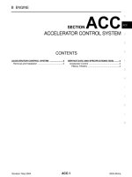
SECTION
A
B
LAN
Revision: May 2004 2003 Altima
CAN
PRECAUTIONS 2
Precautions for Supplemental Restraint System
(SRS) “AIR BAG” and “SEAT BELT PRE-TEN-
SIONER” 2
Precautions For Trouble Diagnosis 2
CAN SYSTEM 2
Precautions For Harness Repair 2
CAN SYSTEM 2
CAN COMMUNICATION 3
System Description 3
FOR TCS MODELS 3
FOR A/T MODELS 4
FOR M/T MODELS 5
CAN SYSTEM (FOR TCS MODELS) 7
System Description 7
Component Parts and Harness Connector Location 7
Wiring Diagram — CAN — 8
Work Flow 10
CHECK SHEET 11
CHECK SHEET RESULTS (EXAMPLE) 12
Circuit Check Between TCM and Combination
Meter 17
Circuit Check Between Combination Meter and
BCM 18
Circuit Check Between BCM and ABS Actuator and
Electric Unit (Control Unit) 19
ECM Circuit Check 21
TCM Circuit Check 21
Combination Meter Circuit Check 22
BCM Circuit Check 22
ABS Actuator and Electric Unit (Control Unit) Circuit
Check 23
IPDM E/R Circuit Check 23
CAN Communication Circuit Check 24
IPDM E/R Ignition Relay Circuit Check 27
Component Inspection 27
ECM/IPDM E/R INTERNAL CIRCUIT INSPEC-
TION 27
CAN SYSTEM (FOR A/T MODELS) 28
System Description 28
Component Parts and Harness Connector Location 28
Wiring Diagram — CAN — 29
Work Flow 31
CHECK SHEET 32
CHECK SHEET RESULTS (EXAMPLE) 33
Circuit Check Between TCM and Combination
Meter 36
Circuit Check Between Combination Meter and
BCM 38
ECM Circuit Check 38
TCM Circuit Check 39
Combination Meter Circuit Check 39
BCM Circuit Check 40
IPDM E/R Circuit Check 40
CAN Communication Circuit Check 41
IPDM E/R Ignition Relay Circuit Check 44
IPDM E/R Check 44
Component Inspection 44
ECM/IPDM E/R INTERNAL CIRCUIT INSPEC-
TION 44
CAN SYSTEM (FOR M/T MODELS) 45
System Description 45
Component Parts and Harness Connector Location 45
Wiring Diagram — CAN — 46
Work Flow 48
CHECK SHEET 49
CHECK SHEET RESULTS (EXAMPLE) 50
Circuit Check Between Combination Meter and
BCM 52
ECM Circuit Check 53
Combination Meter Circuit Check 54
BCM Circuit Check 54
IPDM E/R Circuit Check 55
CAN Communication Circuit Check 56
Component Inspection 59
ECM/IPDM E/R INTERNAL CIRCUIT INSPEC-
TION 59
LAN-2
[CAN]
PRECAUTIONS
Revision: May 2004 2003 Altima
PRECAUTIONS PFP:00001
Precautions for Supplemental Restraint System (SRS) “AIR BAG” and “SEAT
BELT PRE-TENSIONER”
EKS00651
The Supplemental Restraint System such as “AIR BAG” and “SEAT BELT PRE-TENSIONER”, used along
with a front seat belt, helps to reduce the risk or severity of injury to the driver and front passenger for certain
types of collision. This system includes seat belt switch inputs and dual stage front air bag modules. The SRS
system uses the seat belt switches to determine the front air bag deployment, and may only deploy one front
air bag, depending on the severity of a collision and whether the front occupants are belted or unbelted.
Information necessary to service the system safely is included in the SRS and SB section of this Service Man-
ual.
WARNING:
● To avoid rendering the SRS inoperative, which could increase the risk of personal injury or death
in the event of a collision which would result in air bag inflation, all maintenance must be per-
formed by an authorized NISSAN/INFINITI dealer.
● Improper maintenance, including incorrect removal and installation of the SRS, can lead to per-
sonal injury caused by unintentional activation of the system. For removal of Spiral Cable and Air
Bag Module, see the SRS section.
● Do not use electrical test equipment on any circuit related to the SRS unless instructed to in this
Service Manual. SRS wiring harnesses can be identified by yellow and/or orange harnesses or
harness connectors.
Precautions For Trouble Diagnosis
EKS003HN
CAN SYSTEM
● Do not apply voltage of 7.0V or higher to the measurement terminals.
● Use the tester with its open terminal voltage being 7.0V or less.
● Be sure to turn ignition switch off and disconnect negative battery terminal before checking the circuit.
Precautions For Harness Repair
EKS003HO
CAN SYSTEM
● Solder the repaired parts, and wrap with tape. [Frays of twisted
line must be within 110 mm (4.33 in)]
● Do not perform bypass wire connections for the repair parts.
(The spliced wire will become separated and the characteristics
of twisted line will be lost.)
PKIA0306E
PKIA0307E
CAN COMMUNICATION
LAN-3
[CAN]
C
D
E
F
G
H
I
J
L
M
A
B
LAN
Revision: May 2004 2003 Altima
CAN COMMUNICATION PFP:23710
System Description
EKS003HP
CAN (Controller Area Network) is a serial communication line for real time application. It is an on-vehicle mul-
tiplex communication line with high data communication speed and excellent error detection ability. Many elec-
tronic control units are equipped onto a vehicle, and each control unit shares information and links with other
control units during operation (not independent). In CAN communication, control units are connected with 2
communication lines (CAN H line, CAN L line) allowing a high rate of information transmission with less wiring.
Each control unit transmits/receives data but selectively reads required data only.
FOR TCS MODELS
System diagram
Input/output signal chart
T: Transmit R: Receive
LKIA0015E
Signals ECM TCM
COMBINA-
TION
METER
BCM
ABS/TCS
control unit
IPDM E/R
Engine speed signal T R R
Engine coolant temperature signal T R
Accelerator pedal position signal T
Fuel consumption monitor signal T R
A/T warning lamp signal T R
A/T position indicator signal R T R
R
(R range only)
R
ABS operation signal R T
TCS operation signal R R T
Air conditioner switch signal R T
Air conditioner compressor signal R T
A/C compressor request signal T R
Cooling fan motor operation signal R T
Cooling fan speed request signal T R
Position lights request R T R
Position lights status R T
Low beam request TR
Low beam status R R T
High beam request R T R
High beam status R R T
Front fog lights request T R
Front fog light status R T
OD cancel switch signal R T R
Brake switch signal R T
LAN-4
[CAN]
CAN COMMUNICATION
Revision: May 2004 2003 Altima
FOR A/T MODELS
System diagram
Input/output signal chart
T: Transmit R: Receive
Vehicle speed signal
RT
RTR
Oil pressure switch R T
Sleep request1 R T
Sleep request2 TR
N range switch signal R T
P range switch signal R T
Seat belt buckle switch signal T R
Door switch signal R T R
Tail lamp request R T R
Turn indicator signal R T
Buzzer output signal R T
Trunk switch signal R T
ASCD main switch signal T R
ASCD cruise signal T R
Wiper operation RT
Wiper stop position signal R T
Rear window defogger switch signal T R
Rear window defogger control sig-
nal
RRT
Signals ECM TCM
COMBINA-
TION
METER
BCM
ABS/TCS
control unit
IPDM E/R
LKIA0017E
Signals ECM TCM
COMBINATION
METER
BCM IPDM E/R
Engine speed signal T R
Engine coolant temperature signal T R
Accelerator pedal position signal T R
Fuel consumption monitor signal T R
A/T warning lamp signal T R
A/T position indicator signal R T R
R
(R range only)
Air conditioner switch signal R T
Air conditioner compressor signal R T
A/C compressor request signal T R
CAN COMMUNICATION
LAN-5
[CAN]
C
D
E
F
G
H
I
J
L
M
A
B
LAN
Revision: May 2004 2003 Altima
FOR M/T MODELS
System diagram
Blower fan switch signal
R
(QR25DE)
T
Cooling fan motor operation signal R T
Cooling fan speed request signal T R
Position lights request R T R
Position lights status RT
Low beam request TR
Low beam status R R T
High beam request R T R
High beam status R R T
Front fog lights request TR
Front fog light status RT
OD cancel switch signal R T R
Brake switch signal R T
Vehicle speed signal
RT
RTR
Oil pressure switch R T
Sleep request1 R T
Sleep request2 TR
N range switch signal R T
P range switch signal R T
Seat belt buckle switch signal T R
Door switch signal R T R
Tail lamp request R T R
Turn indicator signal R T
Buzzer output signal R T
Trunk switch signal R T
ASCD main switch signal T R
ASCD cruise signal T R
Wiper operation RT
Wiper stop position signal RT
Rear window defogger switch signal T R
Rear window defogger control signal R R T
Signals ECM TCM
COMBINATION
METER
BCM IPDM E/R
LKIA0018E
LAN-6
[CAN]
CAN COMMUNICATION
Revision: May 2004 2003 Altima
Input/output signal chart
T: Transmit R: Receive
Signals ECM
COMBINATION
METER
BCM IPDM E/R
Engine speed signal T
Engine coolant temperature signal T
Fuel consumption monitor signal T
Air conditioner switch signal R T
Air conditioner compressor signal R T
A/C compressor request signal T R
Blower fan switch signal
R
(QR25DE)
T
Cooling fan motor operation signal R T
Cooling fan speed request signal T R
Position lights request R T R
Position lights status RT
Low beam request TR
Low beam status R R T
High beam request R T R
High beam status R R T
Front fog lights request TR
Front fog light status RT
Vehicle speed signal R T
Oil pressure switch R T
Sleep request1 R T
Sleep request2 TR
Seat belt buckle switch signal T R
Door switch signal R T R
Tail lamp request R T R
Turn indicator signal R T
Buzzer output signal R T
Trunk switch signal R T
ASCD main switch signal T R
ASCD cruise signal T R
Wiper operation RT
Wiper stop position signal RT
Rear window defogger switch signal T R
Rear window defogger control signal R R T
CAN SYSTEM (FOR TCS MODELS)
LAN-7
[CAN]
C
D
E
F
G
H
I
J
L
M
A
B
LAN
Revision: May 2004 2003 Altima
CAN SYSTEM (FOR TCS MODELS) PFP:23710
System Description
EKS003HQ
CAN (Controller Area Network) is a serial communication line for real time application. It is an on-vehicle mul-
tiplex communication line with high data communication speed and excellent error detection ability. Many elec-
tronic control units are equipped onto a vehicle, and each control unit shares information and links with other
control units during operation (not independent). In CAN communication, control units are connected with 2
communication lines (CAN H line, CAN L line) allowing a high rate of information transmission with less wiring.
Each control unit transmits/receives data but selectively reads required data only.
Component Parts and Harness Connector Location
EKS003HR
LKIA0049E
LAN-8
[CAN]
CAN SYSTEM (FOR TCS MODELS)
Revision: May 2004 2003 Altima
Wiring Diagram — CAN —
EKS003HS
WKWA0298E
CAN SYSTEM (FOR TCS MODELS)
LAN-9
[CAN]
C
D
E
F
G
H
I
J
L
M
A
B
LAN
Revision: May 2004 2003 Altima
WKWA0344E
LAN-10
[CAN]
CAN SYSTEM (FOR TCS MODELS)
Revision: May 2004 2003 Altima
Work Flow
EKS003HT
1. Print all the data of “SELF-DIAG RESULTS” for “ENGINE”, “A/T”, "BCM", and "ABS" displayed on CON-
SULT-II.
2. Print all the data of “CAN DIAG SUPPORT MNTR” for “ENGINE”, “A/T”, "BCM", and "ABS" displayed on
CONSULT-II.
3. Attach the printed sheet of “SELF-DIAG RESULTS” and “CAN DIAG SUPPORT MNTR” onto the check
sheet. Refer to LAN-11, "
CHECK SHEET" .
4. Based on the “CAN DIAG SUPPORT MNTR” results, put check marks onto the items with “UNKWN” or
“NG” in the check sheet table. Refer to LAN-11, "
CHECK SHEET" .
NOTE:
If “NG” is displayed on "INITIAL DIAG (initial diagnosis)" as “CAN DIAG SUPPORT MNTR” for the diag-
nosed control unit, replace the control unit.
5. According to the check sheet results (example), start inspection. Refer to LAN-12, "
CHECK SHEET
RESULTS (EXAMPLE)" .
PKIA8260E
PKIA8343E
CAN SYSTEM (FOR TCS MODELS)
LAN-11
[CAN]
C
D
E
F
G
H
I
J
L
M
A
B
LAN
Revision: May 2004 2003 Altima
CHECK SHEET
LKIA0525E
LAN-12
[CAN]
CAN SYSTEM (FOR TCS MODELS)
Revision: May 2004 2003 Altima
CHECK SHEET RESULTS (EXAMPLE)
Case 1
Replace ECM.
Case 2
Replace TCM.
LKIA0526E
WKIA2974E
WKIA2975E
WKIA2976E
CAN SYSTEM (FOR TCS MODELS)
LAN-13
[CAN]
C
D
E
F
G
H
I
J
L
M
A
B
LAN
Revision: May 2004 2003 Altima
Case 3
Replace BCM.
Case 4
Replace ABS actuator and electric unit (control unit). Refer to BRC-44, "Removal and Installation" .
WKIA2977E
WKIA2978E
WKIA2979E
WKIA2980E
LAN-14
[CAN]
CAN SYSTEM (FOR TCS MODELS)
Revision: May 2004 2003 Altima
Case 5
Check harness between TCM and combination meter. Refer to LAN-17, "Circuit Check Between TCM and
Combination Meter" .
Case 6
Check harness between combination meter and BCM. Refer to LAN-18, "Circuit Check Between Combination
Meter and BCM" .
Case 7
Check harness between BCM and ABS actuator and electric unit (control unit). Refer to LAN-19, "Circuit
Check Between BCM and ABS Actuator and Electric Unit (Control Unit)" .
Case 8
Check ECM circuit. Refer to LAN-21, "ECM Circuit Check" .
WKIA2983E
WKIA2984E
WKIA2985E
WKIA2986E
CAN SYSTEM (FOR TCS MODELS)
LAN-15
[CAN]
C
D
E
F
G
H
I
J
L
M
A
B
LAN
Revision: May 2004 2003 Altima
Case 9
Check TCM circuit. Refer to LAN-21, "TCM Circuit Check" .
Case 10
Check combination meter circuit. Refer to LAN-22, "Combination Meter Circuit Check" .
Case 11
Check BCM circuit. Refer to LAN-22, "BCM Circuit Check" .
Case 12
Check ABS actuator and electric unit (control unit) circuit. Refer to LAN-23, "ABS Actuator and Electric Unit
(Control Unit) Circuit Check" .
WKIA2987E
WKIA2988E
WKIA2989E
WKIA2990E
LAN-16
[CAN]
CAN SYSTEM (FOR TCS MODELS)
Revision: May 2004 2003 Altima
Case 13
Check IPDM E/R circuit. Refer to LAN-23, "IPDM E/R Circuit Check" .
Case 14
Check CAN communication circuit. Refer to LAN-24, "CAN Communication Circuit Check" .
Case 15
Check IPDM E/R ignition relay circuit. Refer to LAN-27, "IPDM E/R Ignition Relay Circuit Check" .
WKIA2991E
WKIA2992E
WKIA2993E
WKIA2994E
CAN SYSTEM (FOR TCS MODELS)
LAN-17
[CAN]
C
D
E
F
G
H
I
J
L
M
A
B
LAN
Revision: May 2004 2003 Altima
Circuit Check Between TCM and Combination Meter
EKS003HU
1. CHECK CONNECTOR
1. Turn ignition switch OFF.
2. Disconnect the negative battery terminal.
3. Check following terminals and connector for damage, bent or loose connection (control module-side,
meter-side and harness-side).
● TCM.
● Combination meter.
● Between TCM and combination meter.
OK or NG
OK >> GO TO 2.
NG >> Repair terminal or connector.
2. CHECK HARNESS FOR OPEN CIRCUIT
1. Disconnect TCM connector and harness connector F59.
2. Check continuity between TCM harness connector F56 termi-
nals 5 (L), 6 (Y) and harness connector F59 terminals 23 (L), 22
(Y).
OK or NG
OK >> GO TO 3.
NG >> Repair harness.
5 (L) – 23 (L) : Continuity should exist.
6 (Y) – 22 (Y) : Continuity should exist.
LKIA0019E
LAN-18
[CAN]
CAN SYSTEM (FOR TCS MODELS)
Revision: May 2004 2003 Altima
3. CHECK HARNESS FOR OPEN CIRCUIT
1. Disconnect combination meter connector.
2. Check continuity between harness connector M71 terminals 23
(L), 22 (Y) and combination meter harness connector M24 termi-
nals 1 (L), 2 (Y).
OK or NG
OK >> Connect all the connectors and diagnose again. Refer
to LAN-10, "
Work Flow" .
NG >> Repair harness.
Circuit Check Between Combination Meter and BCM
EKS003HV
1. CHECK CONNECTOR
1. Turn ignition switch OFF.
2. Disconnect the negative battery terminal.
3. Check following terminals and connector for damage, bent or loose connection (meter-side, control mod-
ule-side and harness-side).
● Combination meter.
● BCM.
OK or NG
OK >> GO TO 2.
NG >> Repair terminal or connector.
23 (L) – 1 (L) : Continuity should exist.
22 (Y) – 2 (Y) : Continuity should exist.
LKIA0020E
CAN SYSTEM (FOR TCS MODELS)
LAN-19
[CAN]
C
D
E
F
G
H
I
J
L
M
A
B
LAN
Revision: May 2004 2003 Altima
2. CHECK HARNESS FOR OPEN CIRCUIT
1. Disconnect combination meter connector and BCM connector.
2. Check continuity between combination meter harness connector
M24 terminals 1 (L), 2 (Y) and BCM harness connector M18 ter-
minals 70 (L), 71 (Y).
OK or NG
OK >> Connect all the connectors and diagnose again. Refer
to LAN-10, "
Work Flow" .
NG >> Repair harness.
Circuit Check Between BCM and ABS Actuator and Electric Unit (Control Unit)
EKS003HW
1. CHECK CONNECOTR
1. Turn ignition switch OFF.
2. Disconnect the negative battery terminal.
3. Check following terminals and connector for damage, bent or loose connection (control module-side, con-
trol unit-side and harness-side).
● BCM.
● ABS actuator and electric unit (control unit).
● Between BCM and ABS actuator and electric unit (control unit).
OK or NG
OK >> GO TO 2.
NG >> Repair terminal or connector.
1 (L) – 70 (L) : Continuity should exist.
2 (Y) – 71 (Y) : Continuity should exist.
LKIA0021E
LAN-20
[CAN]
CAN SYSTEM (FOR TCS MODELS)
Revision: May 2004 2003 Altima
2. CHECK HARNESS FOR OPEN CIRCUIT
1. Disconnect BCM connector and harness connector M7.
2. Check continuity between BCM harness connector M18 termi-
nals 70 (L), 71 (Y) and harness connector M7 terminals 10 (L), 9
(Y).
OK or NG
OK >> GO TO 3.
NG >> Repair harness.
3. CHECK HARNESS FOR OPEN CIRCUIT
1. Disconnect harness connector E27.
2. Check continuity between harness connector E28 terminals 10
(L), 9 (Y) and harness connector E27 terminals 11A (L), 12A (Y).
OK or NG
OK >> GO TO 4.
NG >> Repair harness.
70 (L) – 10 (L) : Continuity should exist.
71 (Y) – 9 (Y) : Continuity should exist.
LKIA0022E
10 (L) – 11A (L) : Continuity should exist.
9 (Y) – 12A (Y) : Continuity should exist.
LKIA0023E
CAN SYSTEM (FOR TCS MODELS)
LAN-21
[CAN]
C
D
E
F
G
H
I
J
L
M
A
B
LAN
Revision: May 2004 2003 Altima
4. CHECK HARNESS FOR OPEN CIRCUIT
1. Disconnect ABS actuator and electric unit (control unit) connector.
2. Check continuity between harness connector E130 terminals
11A (L), 12A (Y) and ABS actuator and electric unit (control unit)
connector harness connector E125 terminals 30 (L), 29 (Y).
OK or NG
OK >> Connect all the connectors and diagnose again. Refer
to LAN-10, "
Work Flow" .
NG >> Repair harness.
ECM Circuit Check
EKS003HX
1. CHECK CONNECTOR
1. Turn ignition switch OFF.
2. Disconnect the negative battery terminal.
3. Check the terminals and connector of ECM for damage, bent or loose connection (control module-side
and harness-side).
OK or NG
OK >> GO TO 2.
NG >> Repair terminal or connector.
2. CHECK HARNESS FOR OPEN CIRCUIT
1. Disconnect ECM connector.
2. Check resistance between ECM harness connector F54 termi-
nals 109 (L) and 113 (Y).
OK or NG
OK >> Replace ECM.
NG >> Repair harness between harness connector F59 and
ECM.
TCM Circuit Check
EKS003HY
1. CHECK CONNECTOR
1. Turn ignition switch OFF.
2. Disconnect the negative battery terminal.
3. Check the terminals and connector of TCM for damage, bent or loose connection (control module-side
and harness-side).
OK or NG
OK >> GO TO 2.
NG >> Repair terminal or connector.
11A (L) – 30 (L) : Continuity should exist.
12A (Y) – 29 (Y) : Continuity should exist.
LKIA0024E
109 (L) – 113 (Y) : Approx. 108 – 132Ω
LKIA0025E
LAN-22
[CAN]
CAN SYSTEM (FOR TCS MODELS)
Revision: May 2004 2003 Altima
2. CHECK HARNESS FOR OPEN CIRCUIT
1. Disconnect TCM connector.
2. Check resistance between TCM harness connector F56 termi-
nals 5 (L) and 6 (Y).
OK or NG
OK >> Replace TCM.
NG >> Repair harness between harness connector F59 and
TCM.
Combination Meter Circuit Check
EKS003HZ
1. CHECK CONNECTOR
1. Turn ignition switch OFF.
2. Disconnect the negative battery terminal.
3. Check terminals and connector of combination meter for damage, bent or loose connection (meter-side
and harness-side).
OK or NG
OK >> GO TO 2.
NG >> Repair terminal or connector.
2. CHECK HARNESS FOR OPEN CIRCUIT
1. Disconnect combination meter connector.
2. Check resistance between combination meter harness connec-
tor M24 terminals 1 (L) and 2 (Y).
OK or NG
OK >> Replace combination meter.
NG >> Repair harness between harness connector M71 and
combination meter.
BCM Circuit Check
EKS003I0
1. CHECK CONNECTOR
1. Turn ignition switch OFF.
2. Disconnect the negative battery terminal.
3. Check the terminals and connector of BCM for damage, bent or loose connection (control module-side
and harness-side).
OK or NG
OK >> GO TO 2.
NG >> Repair terminal or connector.
5 (L) – 6 (Y) : Approx. 54 – 66Ω
LKIA0026E
1 (L) – 2 (Y) : Approx. 54 – 66Ω
LKIA0027E
CAN SYSTEM (FOR TCS MODELS)
LAN-23
[CAN]
C
D
E
F
G
H
I
J
L
M
A
B
LAN
Revision: May 2004 2003 Altima
2. CHECK HARNESS FOR OPEN CIRCUIT
1. Disconnect BCM connector.
2. Check resistance between BCM harness connector M18 termi-
nals 70 (L) and 71 (Y).
OK or NG
OK >> Replace BCM.
NG >> Repair harness between harness connector M7 and
BCM.
ABS Actuator and Electric Unit (Control Unit) Circuit Check
EKS003I1
1. CHECK CONNECTOR
1. Turn ignition switch OFF.
2. Disconnect the negative battery terminal.
3. Check the terminals and connector of ABS actuator and electric unit (control unit) for damage, bent or
loose connection (control unit-side and harness-side).
OK or NG
OK >> GO TO 2.
NG >> Repair terminal or connector.
2. CHECK HARNESS FOR OPEN CIRCUIT
1. Disconnect ABS actuator and electric unit (control unit) connector.
2. Check resistance between ABS actuator and electric unit (con-
trol unit) harness connector E125 terminals 30 (L) and 29 (Y).
OK or NG
OK >> Replace ABS actuator and electric unit (control unit).
NG >> Repair harness between harness connector E130 and
ABS actuator and electric unit (control unit). Refer to
BRC-92, "
Removal and Installation" .
IPDM E/R Circuit Check
EKS003I2
1. CHECK CONNECTOR
1. Turn ignition switch OFF.
2. Disconnect the negative battery terminal.
3. Check the terminals and connector of IPDM E/R for damage, bent or loose connection (control module-
side and harness-side).
OK or NG
OK >> GO TO 2.
NG >> Repair terminal or connector.
70 (L) – 71 (Y) : Approx. 54 – 66Ω
LKIA0028E
30 (L) – 29 (Y) : Approx. 54 – 66Ω
LKIA0029E
LAN-24
[CAN]
CAN SYSTEM (FOR TCS MODELS)
Revision: May 2004 2003 Altima
2. CHECK HARNESS FOR OPEN CIRCUIT
1. Disconnect IPDM E/R connector.
2. Check resistance between IPDM E/R harness connector E121
terminals 48 (L) and 49 (Y).
OK or NG
OK >> Replace IPDM E/R. Refer to PG-24, "Removal and
Installation of IPDM E/R" .
NG >> Repair harness between harness connector E130 and
IPDM E/R.
CAN Communication Circuit Check
EKS003I3
1. CHECK CONNECTOR
1. Turn ignition switch OFF.
2. Disconnect the negative battery terminal.
3. Check following terminals and connector for damage, bent or loose connection (control module-side, con-
trol unit-side, meter-side and harness-side).
● ECM.
● TCM.
● Combination meter.
● BCM.
● ABS actuator and electric unit (control unit).
● IPDM E/R.
● Between ECM and IPDM E/R.
OK or NG
OK >> GO TO 2.
NG >> Repair terminal or connector.
2. CHECK HARNESS FOR SHORT CIRCUIT
1. Disconnect ECM connector, TCM connector and harness connector F59.
2. Check continuity between ECM harness connector F54 termi-
nals 109 (L) and 113 (Y).
OK or NG
OK >> GO TO 3.
NG >>
● Repair harness between ECM and harness connector
F59.
● Repair harness between TCM and harness connector
F59.
48 (L) – 49 (Y) : Approx. 108 – 132Ω
LKIA0030E
109 (L) – 113 (Y) : Continuity should not exist.
LKIA0025E
CAN SYSTEM (FOR TCS MODELS)
LAN-25
[CAN]
C
D
E
F
G
H
I
J
L
M
A
B
LAN
Revision: May 2004 2003 Altima
3. CHECK HARNESS FOR SHORT CIRCUIT
Check continuity between ECM harness connector F54 terminals
109 (L), 113 (Y) and ground.
OK or NG
OK >> GO TO 4.
NG >>
● Repair harness between ECM and harness connector
F59.
● Repair harness between TCM and harness connector
F59.
4. CHECK HARNESS FOR SHORT CIRCUIT
1. Disconnect combination meter connector, BCM connector and harness connector M7.
2. Check continuity between data link connector M22 terminals 6
(L) and 3 (Y).
OK or NG
OK >> GO TO 5.
NG >>
● Repair harness between harness connector M71 and
harness connector M7.
● Repair harness between harness connector M71 and
combination meter.
● Repair harness between harness connector M71 and
data link connector.
● Repair harness between harness connector M71 and BCM.
5. CHECK HARNESS FOR SHORT CIRCUIT
Check continuity between data link connector M22 terminals 6 (L), 3
(Y) and ground.
OK or NG
OK >> GO TO 6.
NG >>
● Repair harness between harness connector M71 and
harness connector M7.
● Repair harness between harness connector M71 and
combination meter.
● Repair harness between harness connector M71 and data link connector.
● Repair harness between harness connector M71 and BCM.
109 (L) – ground : Continuity should not exist.
113 (Y) – ground : Continuity should not exist.
LKIA0031E
6 (L) – 3 (Y) : Continuity should not exist.
LKIA0032E
6 (L) – ground : Continuity should not exist.
3 (Y) – ground : Continuity should not exist.
LKIA0033E