STC hệ THỐNG điều KHIỂN lái NISSAN VERSA HATCH BACK 2012
Bạn đang xem bản rút gọn của tài liệu. Xem và tải ngay bản đầy đủ của tài liệu tại đây (786.5 KB, 30 trang )
STC-1
STEERING
C
D
E
F
H
I
J
K
L
M
SECTION STC
A
B
STC
N
O
P
CONTENTS
STEERING CONTROL SYSTEM
EPS
BASIC INSPECTION
3
DIAGNOSIS AND REPAIR WORKFLOW 3
Work Flow 3
SYSTEM DESCRIPTION 5
EPS SYSTEM 5
System Diagram 5
System Description 5
Component Parts Location 6
Component Description 6
DIAGNOSIS SYSTEM (EPS CONTROL UNIT)
7
CONSULT Function 7
DTC/CIRCUIT DIAGNOSIS 8
C1601 BATTERY POWER SUPPLY 8
Description 8
DTC Logic 8
Diagnosis Procedure 8
C1604 TORQUE SENSOR 10
Description 10
DTC Logic 10
Diagnosis Procedure 10
C1606 EPS MOTOR 12
Description 12
DTC Logic 12
Diagnosis Procedure 12
Component Inspection 12
C1607, C1608 EPS CONTROL UNIT 14
Description 14
DTC Logic 14
Diagnosis Procedure 14
C1609 VEHICLE SPEED SIGNAL 15
Description 15
DTC Logic 15
Diagnosis Procedure 15
C1610 ENGINE STATUS SIGNAL 16
Description 16
DTC Logic 16
Diagnosis Procedure 16
U1000 CAN COMM CIRCUIT 17
Description 17
DTC Logic 17
Diagnosis Procedure 17
EPS WARNING LAMP 18
Description 18
Component Function Check 18
Diagnosis Procedure 18
ECU DIAGNOSIS INFORMATION 19
EPS CONTROL UNIT 19
Reference Value 19
Wiring Diagram - ELECTRONICALLY CON-
TROLLED POWER STEERING SYSTEM -
21
Fail-Safe 22
DTC Inspection Priority Chart 23
DTC Index 23
SYMPTOM DIAGNOSIS 24
EPS WARNING LAMP DOES NOT TURN ON 24
Description 24
Diagnosis Procedure 24
EPS WARNING LAMP DOES NOT TURN
OFF
25
Description 25
Diagnosis Procedure 25
STEERING WHEEL TURNING FORCE IS
HEAVY OR LIGHT
26
Revision: July 2011 2012 Versa
STC-2
Description 26
Diagnosis Procedure 26
UNBALANCE STEERING WHEEL TURNING
FORCE AND RETURN BETWEEN RIGHT
AND LEFT
27
Description 27
Diagnosis Procedure 27
UNBALANCE STEERING WHEEL TURNING
FORCE (TORQUE VARIATION)
28
Description 28
Diagnosis Procedure 28
PRECAUTION 29
PRECAUTIONS 29
Precaution for Supplemental Restraint System
(SRS) "AIR BAG" and "SEAT BELT PRE-TEN-
SIONER"
29
Precaution Necessary for Steering Wheel Rota-
tion After Battery Disconnect
29
Service Notice or Precaution for EPS System 30
Revision: July 2011 2012 Versa
DIAGNOSIS AND REPAIR WORKFLOW
STC-3
< BASIC INSPECTION >
[EPS]
C
D
E
F
H
I
J
K
L
M
A
B
STC
N
O
P
BASIC INSPECTION
DIAGNOSIS AND REPAIR WORKFLOW
Work Flow INFOID:0000000007328978
1.OBTAIN INFORMATION ABOUT SYMPTOM
Interview the customer to obtain as much information as possible about the conditions and environment under
which the malfunction occurs.
>> GO TO 2.
2.CHECK DTC
1. Check for DTC.
2. If a DTC exists, perform the following operations.
- Records the DTCs.
- Erase DTCs
- Check that the root cause clarified with DTC matches to the malfunction information described by the cus-
tomer.
3. Check also the related service information or others.
Do malfunction information or DTC exist?
Malfunction information and DTC exist. >>GO TO 3.
Malfunction information exists but no DTC. >>GO TO 4.
No malfunction information, but DTC exists. >>GO TO 5.
3.REPRODUCE THE MALFUNCTION INFORMATION
Check the malfunction described by the customer on the vehicle.
Record the status of each signal when a symptom occurs with “Data Monitor” in CONSULT.
Inspect the relation of the information and the condition when it occurs.
>> GO TO 5.
4.CHECK THE MALFUNCTION
Check the malfunction described by the customer on the vehicle.
Record the status of each signal when a symptom occurs with “Data Monitor” in CONSULT.
Inspect the relation of the information and the condition when it occurs.
>> GO TO 6.
5.PERFORM “DTC CONFIRMATION PROCEDURE”
Perform the “DTC conformation procedure” to the detected DTC and check that the DTC is detected again.
Refer to STC-23, "
DTC Inspection Priority Chart" when multiple DTCs are detected, and then judge the order
for performing the diagnosis.
Is any DTC detected?
YES >> GO TO 7.
NO >> Follow GI-9, "
How to Follow Trouble Diagnosis" to check.
6.IDENTIFY MALFUNCTIONING SYSTEM WITH “SYMPTOM DIAGNOSIS”
Use the “Symptom diagnosis” from the symptom inspection result in step 4. Then identify where to start per-
forming the diagnosis based on the possible causes and the symptoms.
>> GO TO 7.
7.IDENTIFY MALFUNCTIONING PARTS WITH “COMPONENT DIAGNOSIS”
Perform the inspection with the “component diagnosis” of the applicable system.
NOTE:
The “component diagnosis” mainly consists of the check for an open circuit.
Revision: July 2011 2012 Versa
STC-4
< BASIC INSPECTION >
[EPS]
DIAGNOSIS AND REPAIR WORKFLOW
The circuit check in the diagnosis procedure also requires the check for a short circuit. Refer to GI-25, "How to
Perform Efficient Diagnosis for an Electrical Incident" for details.
>> GO TO 8.
8.REPAIR OR REPLACE THE MALFUNCTIONING PARTS
1. Repair or replace the part detected as malfunctioning.
2. After repairing or replacing, reinstall/reconnect parts or connectors removed/disconnected in the “compo-
nent diagnosis”, and then erase the DTC.
>> GO TO 9.
9.FINAL CHECK
Perform the “DTC confirmation procedure” or “component Inspection” to check that the repair is correctly per-
formed. Check that malfunctions are not reproduced when obtaining the malfunction information from the cus-
tomer, referring to the symptom inspection result in step 3 or 4.
Is the check result normal?
YES >> Trouble diagnosis is completed.
NO-1 >> The DTC is reproduced. GO TO 7.
NO-2 >> The symptom is reproduced. GO TO 6.
Revision: July 2011 2012 Versa
EPS SYSTEM
STC-5
< SYSTEM DESCRIPTION >
[EPS]
C
D
E
F
H
I
J
K
L
M
A
B
STC
N
O
P
SYSTEM DESCRIPTION
EPS SYSTEM
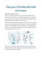
System Diagram INFOID:0000000007328979
System Description INFOID:0000000007328980
• EPS control unit performs an arithmetical operation on data, such as steering wheel turning force (sensor
signal) from the torque sensor, vehicle speed signal, etc. Then it generates an optimum assist torque signal
to the EPS motor according to the driving condition.
• EPS control unit decreases the output signal to EPS motor while extremely using the power steering func-
tion (e.g., full steering) consecutively for protecting EPS motor and EPS control unit (Overload protection
control). While activating overload protection control, the assist torque gradually decreases, and the steering
wheel turning force becomes heavy. The normal assist torque reactivates by no steering.
• In case of an error in the electrical system, the fail-safe function stops output signals to the EPS motor. Then
the previous state is changed to the manual steering state.
• Self-diagnosis can be done with CONSULT.
• EPS control unit will decrease assistance under the following 2 conditions.
- Extensive steering at low speed will cause the ECU and MOTOR to heat up, once temperature reaches crit-
ical point ECU will reduce current to reduce heat up. System will recover as temperature lowers (reduced or
no assistance).
- Holding steering on rack-end (full lock) for 1 second will cause the system to engage rack-end protection.
This reduces assistance down to 50% in order to prevent heat up. Assistance is immediately returned to
100% when steering released or turned away from rack-end.
- Communicates the signal from each control unit via CAN communication.
SGIA1701E
Control unit Signal status
ECM
Transmits mainly the following signals to EPS control unit via CAN communication.
Engine status signal
ABS actuator and electric unit
(control unit)
Transmits mainly the following signals to EPS control unit via CAN communication.
Vehicle speed signal
Combination meter
• Transmits mainly the following signals to EPS control unit via CAN communication.
Vehicle speed signal
• EPS warning lamp signal is received from the EPS control unit via CAN communication.
Revision: July 2011 2012 Versa
STC-6
< SYSTEM DESCRIPTION >
[EPS]
EPS SYSTEM
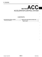
Component Parts Location
INFOID:0000000007328981
Component Description INFOID:0000000007328982
SGIA1623E
Components parts Reference
EPS control unit STC-14, "
Description"
EPS motor STC-12, "Description"
Torque sensor STC-10, "Description"
Reduction gear
Reduction gear increases the assist torque provided from EPS
motor with worm gears, and outputs to the column shaft.
EPS warning lamp STC-18, "
Description"
Revision: July 2011 2012 Versa
DIAGNOSIS SYSTEM (EPS CONTROL UNIT)
STC-7
< SYSTEM DESCRIPTION >
[EPS]
C
D
E
F
H
I
J
K
L
M
A
B
STC
N
O
P
DIAGNOSIS SYSTEM (EPS CONTROL UNIT)
CONSULT Function INFOID:0000000007328983
FUNCTION
CONSULT can display each diagnostic item using the diagnostic test modes shown following.
ECU IDENTIFICATION
Displays the part number stored in the control unit.
SELF-DIAG RESULTS MODE
Display Item List
Refer to STC-23, "DTC Index".
CAUTION:
If “CAN COMM CIRCUIT [U1000]” is displayed with other DTCs, first perform the trouble diagnosis for
CAN communication line.
DATA MONITOR MODE
Display Item List
*1: Almost in accordance with the value of MOTOR SIG. It is not a malfunction though these values are not accorded when steering
quickly.
*2: It is not a malfunction, though it might not be corresponding just after ignition switch in turned ON.
Diagnostic test mode Function
ECU identification Steering column assembly number can be read.
Self diagnostic result Self-diagnostic results can be read and erased quickly.
CAN diag support MNTR The results of transmit/receive diagnosis of CAN communication can be read.
Data monitor Input/Output data in the EPS control unit can be read.
Monitor item (Unit) Remarks
BATTERY VOLT (V) Displays the power supply voltage for EPS control unit.
TORQUE SENSOR (Nm) Displays steering wheel turning force detected by torque sensor.
MOTOR CURRENT (A) Displays the current value consumed by EPS motor.
MOTOR SIG (A)
*1
Displays the current commanded value to EPS motor.
VEHICLE SPEED (km/h) or (MPH)
*2
Vehicle speed is displayed from vehicle speed signal via CAN communication.
WARNING LAMP (On/Off) EPS warning lamp control status is displayed.
ENGINE STATUS (Stop/Run) Engine speed is displayed from engine status signal via CAN communication.
Revision: July 2011 2012 Versa
STC-8
< DTC/CIRCUIT DIAGNOSIS >
[EPS]
C1601 BATTERY POWER SUPPLY
DTC/CIRCUIT DIAGNOSIS
C1601 BATTERY POWER SUPPLY
Description INFOID:0000000007328984
Power is supplied from the battery to EPS control unit.
DTC Logic INFOID:0000000007328985
DTC DETECTION LOGIC
DTC CONFIRMATION PROCEDURE
1.DTC REPRODUCTION PROCEDURE
With CONSULT
1. Turn the ignition switch OFF to ON.
2. Perform EPS control unit self-diagnosis.
Is DTC
“C1601” detected?
YES >> Proceed to diagnosis procedure. Refer to STC-8, "Diagnosis Procedure".
NO >> Inspection End.
Diagnosis Procedure INFOID:0000000007328986
1.CHECK EPS CONTROL UNIT GROUND CIRCUIT
1. Turn ignition switch OFF.
2. Disconnect EPS control unit harness connector.
3. Check continuity between EPS control unit harness connector
terminal and ground.
Is the inspection result normal?
YES >> GO TO 2.
NO >> Repair open circuit or short to ground or short to power
in harness or connectors.
2.CHECK EPS CONTROL UNIT POWER SUPPLY CIRCUIT
1. Connect EPS control unit harness connector.
2. Check voltage between EPS control unit harness connector
M53 (A), M54 (B) terminals and ground.
3. Turn ignition switch ON.
CAUTION:
Never start the engine.
DTC Display item Malfunction detected condition Possible cause
C1601 BATTERY VOLT
When a power supply voltage to the EPS control unit
is maintained at or above 17.5 V or less than 9 V con-
tinuously for more than five seconds.
• Harness or connector
• EPS control unit
•Fuse
• Power supply system
EPS control unit
—Continuity
Connector Terminal
M54 18 Ground Existed
AWGIA0180ZZ
EPS control unit
—Voltage
Connector Terminal
M53 (A) 10
Ground
Approx. 0 V
M54 (B) 17 Battery voltage
AWGIA0181ZZ
Revision: July 2011 2012 Versa
C1601 BATTERY POWER SUPPLY
STC-9
< DTC/CIRCUIT DIAGNOSIS >
[EPS]
C
D
E
F
H
I
J
K
L
M
A
B
STC
N
O
P
4. Check voltage between EPS control unit harness connector
M53 (A), M54 (B) terminals and ground.
Is the inspection result normal?
YES >> GO TO 3.
NO >> Check the following. If any items are damaged, repair
or replace damaged parts.
• 10A fuse (#2) open
- Harness for short between 10A fuse (#2) and power steering control unit harness connector No.
10 terminal.
• 60A fusible link (M) open
- Harness for short between 60A fusible link (M) and power steering control unit harness connec-
tor No. 10 terminal.
• Harness for open between ignition switch and power steering control unit harness connector
No. 17 terminal.
• Harness for open between battery and power steering control unit harness connector No. 17 ter-
minal.
• Battery or ignition switch.
3.CHECK BATTERY VOLTAGE SIGNAL (1)
With CONSULT
1. Start the engine.
CAUTION:
Stop the vehicle.
2. Select “EPS”, “DATA MONITOR” and “MOTOR VOLT”, and perform the battery voltage inspection.
Is the inspection result normal?
YES >> GO TO 4.
NO >> Replace EPS control unit. Refer to PS-10, "
Removal and Installation".
4.CHECK MOTOR VOLTAGE SIGNAL (2)
With CONSULT
Select “MOTOR VOLT” in “DATA MONITOR” of the EPS control unit. Check motor voltage with the steering
wheel fully turned leftward or rightward.
Is the value in
“DATA MONITOR”“between 9 V and 17.5 V”?
YES >> Check pin terminal and connection of each harness connector for damage or loose connection.
NO >> Check battery power supply and ignition power supply. Refer to STC-21, "
Wiring Diagram - ELEC-
TRONICALLY CONTROLLED POWER STEERING SYSTEM -".
EPS control unit
—Voltage
Connector Terminal
M53 (A) 10
Ground Battery voltage
M54 (B) 17
AWGIA0182ZZ
Monitor item Condition Display value
MOTOR VOLT Engine running Battery voltage
Revision: July 2011 2012 Versa
STC-10
< DTC/CIRCUIT DIAGNOSIS >
[EPS]
C1604 TORQUE SENSOR
C1604 TORQUE SENSOR
Description INFOID:0000000007328987
Torque sensor detects the steering torque, and transmit the signal to EPS control unit.
DTC Logic INFOID:0000000007328988
DTC DETECTION LOGIC
DTC CONFIRMATION PROCEDURE
1.DTC REPRODUCTION PROCEDURE
With CONSULT
1. Turn the ignition switch OFF to ON.
2. Perform EPS control unit self-diagnosis.
Is DTC
“C1604” detected?
YES >> Proceed to diagnosis procedure. Refer to STC-10, "Diagnosis Procedure".
NO >> Inspection End.
Diagnosis Procedure INFOID:0000000007328989
1.CHECK TORQUE SENSOR POWER SUPPLY CIRCUIT
1. Turn ignition switch OFF to ON.
CAUTION:
Never start the engine.
2. Check voltage between EPS control unit harness connector terminals and ground.
CAUTION:
Steering wheel is neutral position. (There is no steering
force.)
Is the inspection result normal?
YES >> GO TO 2.
NO >> Perform the trouble diagnosis for battery power supply
circuit. Refer to STC-8, "
Diagnosis Procedure".
2.CHECK TORQUE SENSOR GROUND CIRCUIT
1. Turn ignition switch OFF.
2. Check continuity between EPS control unit harness connector terminal and ground.
CAUTION:
DTC Display item Malfunction detected condition Possible cause
C1604 TORQUE SENSOR When torque sensor output signal is malfunctioning.
• Harness or connector
• Torque sensor
• EPS control unit
EPS control unit
—Voltage
Connector Terminal
M53 5 Ground Approx. 5 V
AWGIA0183ZZ
Revision: July 2011 2012 Versa
C1604 TORQUE SENSOR
STC-11
< DTC/CIRCUIT DIAGNOSIS >
[EPS]
C
D
E
F
H
I
J
K
L
M
A
B
STC
N
O
P
Steering wheel is neutral position. (There is no steering
force.)
Is the inspection result normal?
YES >> GO TO 3.
NO >> Repair open circuit or short to ground or short to power
in harness or connectors.
3.CHECK TORQUE SENSOR SIGNAL
1. Turn ignition switch ON.
2. Check voltage between EPS control unit harness connector terminal and ground.
CAUTION:
Steering wheel is neutral position. (There is no steering
force.)
3. Start the engine.
4.
Check voltage between torque sensor harness connector termi-
nal and ground while turning the steering wheel.
Is the inspection result normal?
YES >> GO TO 4.
NO >> Torque sensor is malfunction. Replace steering column assembly. Refer to PS-10, "
Removal and
Installation".
4.CHECK CONNECTOR
1. Turn ignition switch OFF.
2. Disconnect torque sensor harness connector.
3. Check terminal for deformation, disconnection, looseness, and so on. If any malfunction is found, repair or
replace terminal.
Is the inspection result normal?
YES >> Replace EPS control unit. Refer to PS-10, "Removal and Installation".
NO >> Repair or replace error-detected parts.
EPS control unit
—Continuity
Connector Terminal
M53 7 Ground Yes
AWGIA0184ZZ
EPS control unit
—Voltage
Connector Terminal
M53
4
Ground Approx. 2.5V
6
AWGIA0185ZZ
Torque sensor
—Voltage
Connector Terminal
M63
1
Ground
1.6 V – 3.4 V
(The value is changed
according to steering
left or right)
3
AWGIA0187ZZ
Revision: July 2011 2012 Versa
STC-12
< DTC/CIRCUIT DIAGNOSIS >
[EPS]
C1606 EPS MOTOR
C1606 EPS MOTOR
Description INFOID:0000000007328990
EPS motor provides the assist torque by the control signal from EPS control unit.
DTC Logic INFOID:0000000007328991
DTC DETECTION LOGIC
DTC CONFIRMATION PROCEDURE
1.DTC REPRODUCTION PROCEDURE
With CONSULT
1. Turn the ignition switch OFF to ON.
2. Perform EPS control unit self-diagnosis.
Is DTC
“C1606” detected?
YES >> Proceed to diagnosis procedure. Refer to STC-12, "Diagnosis Procedure".
NO >> Inspection End.
Diagnosis Procedure INFOID:0000000007328992
1.CHECK EPS MOTOR
Check the EPS motor. Refer to STC-12, "
Component Inspection".
Is the inspection result normal?
YES >> GO TO 2.
NO >> EPS motor is malfunction. Replace steering column assembly. Refer to PS-10, "
Removal and
Installation".
2.CHECK CONNECTOR
1. Turn ignition switch OFF.
2. Disconnect EPS motor harness connector.
3. Check terminal for deformation, disconnection, looseness, and so on. If any malfunction is found, repair or
replace terminal.
Is the inspection result normal?
YES >> Replace EPS control unit. Refer to PS-10, "Removal and Installation".
NO >> Repair or replace error-detected parts.
Component Inspection INFOID:0000000007328993
1.CHECK EPS MOTOR
1. Turn the ignition switch OFF.
2. Disconnect EPS motor harness connector.
DTC Display item Malfunction detected condition Possible cause
C1606 EPS MOTOR
When the motor driver malfunction of EPS control
unit or EPS motor malfunction is detected.
• Harness or connector
• EPS motor
• EPS control unit
Revision: July 2011 2012 Versa
C1606 EPS MOTOR
STC-13
< DTC/CIRCUIT DIAGNOSIS >
[EPS]
C
D
E
F
H
I
J
K
L
M
A
B
STC
N
O
P
3. Check resistance between EPS motor connector terminals.
Is the inspection result normal?
YES >> Inspection End
NO >> EPS motor is malfunction. Replace steering column
assembly. Refer to PS-10, "
Removal and Installation".
EPS motor
Resistance (Approx.)
Term i nal
19 20 0.1 Ω or less
AWGIA0186ZZ
Revision: July 2011 2012 Versa
STC-14
< DTC/CIRCUIT DIAGNOSIS >
[EPS]
C1607, C1608 EPS CONTROL UNIT
C1607, C1608 EPS CONTROL UNIT
Description INFOID:0000000007328994
EPS control unit performs an arithmetical operation on data, such as steering wheel turning force (sensor sig-
nal) from the torque sensor, vehicle speed signal, etc. Then it generates an optimum assist torque signal to the
EPS motor according to the driving condition.
DTC Logic INFOID:0000000007328995
DTC DETECTION LOGIC
DTC CONFIRMATION PROCEDURE
1.DTC REPRODUCTION PROCEDURE
With CONSULT
1. Turn the ignition switch OFF to ON.
2. Perform EPS control unit self-diagnosis.
Is DTC
“C1607” or “C1608” detected?
YES >> Proceed to diagnosis procedure. Refer to STC-14, "Diagnosis Procedure".
NO >> Inspection End.
Diagnosis Procedure INFOID:0000000007328996
1.PERFORM SELF-DIAGNOSIS
With CONSULT
1. Turn the ignition switch OFF to ON.
2. Erase EPS control unit self-diagnostic results.
3. Perform EPS control unit self-diagnosis.
Is DTC
“C1607” or “C1608” detected?
YES >> Replace EPS control unit. Refer to PS-10, "Removal and Installation".
NO >> Check EPS control unit pin terminals for damage or loose connection with harness connector. If
any item are damaged, repair or replace error-detected parts.
DTC Display item Malfunction detected condition Possible cause
C1607 EEPROM
When the memory (EEPROM) system malfunction is
detected in EPS control unit.
EPS control unit
C1608 CONTROL UNIT
When the internal malfunction is detected in EPS
control unit.
Revision: July 2011 2012 Versa
C1609 VEHICLE SPEED SIGNAL
STC-15
< DTC/CIRCUIT DIAGNOSIS >
[EPS]
C
D
E
F
H
I
J
K
L
M
A
B
STC
N
O
P
C1609 VEHICLE SPEED SIGNAL
Description INFOID:0000000007328997
EPS control unit receives the vehicle speed signal from ABS actuator and electric unit (control unit) via CAN
communication line.
DTC Logic INFOID:0000000007328998
DTC DETECTION LOGIC
DTC CONFIRMATION PROCEDURE
1.DTC REPRODUCTION PROCEDURE
With CONSULT
1. Turn the ignition switch OFF to ON.
2. Perform EPS control unit self-diagnosis.
Is DTC
“C1609” detected?
YES >> Proceed to diagnosis procedure. Refer to STC-15, "Diagnosis Procedure".
NO >> Inspection End.
Diagnosis Procedure INFOID:0000000007328999
1.PERFORM ABS ACTUATOR AND ELECTRIC UNIT (CONTROL UNIT) SELF-DIAGNOSIS
With CONSULT
1. Turn the ignition switch OFF to ON.
2. Perform ABS actuator and electrical unit (control unit) self-diagnosis. Refer to BRC-25, "
CONSULT Func-
tion (ABS)".
Is any DTC detected?
YES >> Check the DTC. Refer to BRC-25, "CONSULT Function (ABS)".
NO >> GO TO 2.
2.PERFORM SELF-DIAGNOSIS
With CONSULT
Perform EPS control unit self-diagnosis.
Is DTC
“C1609” detected?
YES >> Replace EPS control unit. Refer to PS-10, "Removal and Installation".
NO >> Check EPS control unit pin terminals for damage or loose connection with harness connector. If
any item are damaged, repair or replace error-detected parts.
DTC Display item Malfunction detected condition Possible cause
C1609 CAN VHCL SPEED
• Malfunction is detected in vehicle speed signal that
is output from ABS actuator and electric unit (con-
trol unit) via CAN communication.
• ABS actuator and electric unit (control unit) input
signal error is detected.
• Harness or connector
• CAN communication line
• EPS control unit
• ABS malfunction
- Vehicle speed signal error
Revision: July 2011 2012 Versa
STC-16
< DTC/CIRCUIT DIAGNOSIS >
[EPS]
C1610 ENGINE STATUS SIGNAL
C1610 ENGINE STATUS SIGNAL
Description INFOID:0000000007329000
EPS control unit receives the engine status signal from ECM via CAN communication line.
DTC Logic INFOID:0000000007329001
DTC DETECTION LOGIC
DTC CONFIRMATION PROCEDURE
1.DTC REPRODUCTION PROCEDURE
With CONSULT
1. Turn the ignition switch OFF to ON.
2. Perform EPS control unit self-diagnosis.
Is DTC
“C1610” detected?
YES >> Proceed to diagnosis procedure. Refer to STC-16, "Diagnosis Procedure".
NO >> Inspection End.
Diagnosis Procedure INFOID:0000000007329002
1.PERFORM ECM SELF-DIAGNOSIS
With CONSULT
1. Turn the ignition switch OFF to ON.
2. Perform ECM self-diagnosis. Refer to EC-119, "
CONSULT Function (ENGINE)".
Is any DTC detected?
YES >> Check the DTC. Refer to EC-9, "U0101-U1001".
NO >> GO TO 2.
2.PERFORM SELF-DIAGNOSIS
With CONSULT
Perform EPS control unit self-diagnosis.
Is DTC
“C1610” detected?
YES >> Replace EPS control unit. Refer to PS-10, "Removal and Installation".
NO >> Check EPS control unit pin terminals for damage or loose connection with harness connector. If
any item are damaged, repair or replace error-detected parts.
DTC Display item Malfunction detected condition Possible cause
C1610 CAN ENG RPM
• Malfunction is detected in engine status signal
that is output from ECM via CAN communica-
tion.
• ECM input signal error is detected.
• Harness or connector
• CAN communication line
• EPS control unit
•ECM
- Engine status signal error
Revision: July 2011 2012 Versa
U1000 CAN COMM CIRCUIT
STC-17
< DTC/CIRCUIT DIAGNOSIS >
[EPS]
C
D
E
F
H
I
J
K
L
M
A
B
STC
N
O
P
U1000 CAN COMM CIRCUIT
Description INFOID:0000000007329003
CAN (Controller Area Network) is a serial communication line for real time application. It is an on-vehicle mul-
tiplex communication line with high data communication speed and excellent error detection ability. Many elec-
tronic control units are equipped onto a vehicle, and each control unit shares information and links with other
control units during operation (not independent). In CAN communication, control units are connected with 2
communication lines (CAN-H line, CAN-L line) allowing a high rate of information transmission with less wiring.
Each control unit communicate data but selectively reads required data only.
DTC Logic INFOID:0000000007329004
DTC DETECTION LOGIC
DTC CONFIRMATION PROCEDURE
1.DTC REPRODUCTION PROCEDURE
With CONSULT
1. Turn the ignition switch OFF to ON.
2. Perform EPS control unit self-diagnosis.
Is DTC
“U1000” detected?
YES >> Proceed to diagnosis procedure. Refer to STC-17, "Diagnosis Procedure".
NO >> Inspection End
Diagnosis Procedure INFOID:0000000007329005
1.PERFORM SELF-DIAGNOSIS
With CONSULT
Perform EPS control unit self-diagnosis.
Is DTC
“U1000” detected?
YES >> CAN specification chart. Refer to LAN-14, "Trouble Diagnosis Flow Chart".
NO >> Inspection End.
DTC Display item Malfunction detected condition Possible cause
U1000 CAN COMM CIRCUIT
EPS control unit is not transmitting/re-
ceiving CAN communication signal for 2
seconds or more.
• CAN communication error
• EPS control unit
Revision: July 2011 2012 Versa
STC-18
< DTC/CIRCUIT DIAGNOSIS >
[EPS]
EPS WARNING LAMP
EPS WARNING LAMP
Description INFOID:0000000007329006
• Turn ON when there is a malfunction in EPS system. If indicates that fail-safe mode is engaged and enters a
manual steering state (Control turning force steering wheel becomes heavy).
• Also turns ON when ignition switch is turned ON, for purpose of lamp check. Turns OFF after the engine
starts, if system is normal.
EPS WARNING LAMP INDICATION
CAUTION:
EPS warning lamp also turns ON due to data reception error, CAN communication error etc.
Component Function Check INFOID:0000000007329007
1.CHECK THE ILLUMINATION OF THE EPS WARNING LAMP
Check that the EPS warning lamp turns ON when ignition switch turns ON. Then, EPS warning lamp turns
OFF after the engine is started.
Is the inspection result normal?
YES >> Inspection End
NO >> Perform trouble diagnosis. Refer to STC-18, "
Diagnosis Procedure".
Diagnosis Procedure INFOID:0000000007329008
1.PERFORM SELF-DIAGNOSIS
With CONSULT
1. Turn the ignition switch OFF to ON.
2. Perform EPS control unit self-diagnosis.
Is any DTC detected?
YES >> Check the DTC. Refer to STC-23, "DTC Index".
NO >> GO TO 2.
2.CHECK EPS WARNING LAMP SIGNAL
With CONSULT
1. Turn the ignition switch ON.
CAUTION:
Never start the engine.
2. On “DATA MONITOR”, select “WARNING LAMP”.
3. Check that the EPS warning lamp is turned ON.
4. Start the engine.
CAUTION:
Stop the vehicle.
5. Check that the EPS warning lamp is turned OFF.
Is the inspection result normal?
YES >> Perform the trouble diagnosis for combination meter power supply circuit. Refer to DI-15, "Power
Supply and Ground Circuit Inspection".
NO >> Replace the EPS control unit. Refer to PS-10, "
Removal and Installation".
Condition EPS warning lamp
Ignition switch ON. (Lamp check) ON
Engine running. OFF
EPS system malfunction [Other diagnostic item] ON
EPS warning lamp ON: On
EPS warning lamp OFF: Off
Revision: July 2011 2012 Versa
EPS CONTROL UNIT
STC-19
< ECU DIAGNOSIS INFORMATION >
[EPS]
C
D
E
F
H
I
J
K
L
M
A
B
STC
N
O
P
ECU DIAGNOSIS INFORMATION
EPS CONTROL UNIT
Reference Value INFOID:0000000007329009
VALUES ON THE DIAGNOSIS TOOL
CAUTION:
The output signal indicates the EPS control unit calculation data. The normal values will be displayed
even in the event that the output circuit (harness) is open.
*1: Almost in accordance with the value of MOTOR SIG. It is not a malfunction though these values are not accorded when steering
quickly.
*2: It is not a malfunction, though it might not be corresponding just after ignition switch in turned ON.
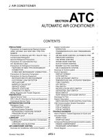
TERMINAL LAYOUT
PHYSICAL VALUES
Monitor item Display content
Data monitor
Condition Display value
MOTOR VOL
Power supply voltage for
EPS control unit
Ignition switch: ON Battery voltage
TORQUE SENSOR
Steering wheel turning
force
Engine running
Steering wheel: Not steering
(There is no steering force)
Approx. 0 Nm
Steering wheel: Right turn Positive value (Nm)
Steering wheel: Left turn Negative value (Nm)
MOTOR CURRENT
Consumption current of
EPS motor
Engine running
Steering wheel: Not steering
(There is no steering force)
Approx. 0 A
Steering wheel: Right or left
turn
Displays consumption cur-
rent of EPS motor (A)
*1
MOTOR SIG
Command current to
EPS motor
Engine running
Steering wheel: Not steering
(There is no steering force)
Approx. 0 A
Steering wheel: Right turn Negative value (A)
Steering wheel: Left turn Positive value (A)
DERATING STAT
Displays overload sta-
tus.
Engine running Off
VEHICLE SPEED Vehicle speed
Vehicle stopped 0 km/h (0 mph)
While driving
Approximately equal to the
indication on speedometer
(inside of ±10%)
*2
WARNING LAMP
EPS warning lamp con-
dition
EPS warning lamp: ON On
EPS warning lamp: OFF Off
ENGINE STATUS Engine status
Engine not running Stop
Engine running Run
SGIA1624E
Revision: July 2011 2012 Versa
STC-20
< ECU DIAGNOSIS INFORMATION >
[EPS]
EPS CONTROL UNIT
Term i nal No.
(Wire Color)
Description
Condition
Value
(Approx.)
+ − Signal name Input/Output
4
(V)
Ground Torque sensor sub Input
Ignition switch: ON
Steering wheel: Not
steering (There is no
steering force)
2.5 V
Engine running
Steering wheel: steer-
ing
1.6 V – 3.4 V
(The value is changed
according to steering
left or right)
5
(BR)
Ground
Torque sensor power
supply
Output Ignition switch: ON 5 V
6
(G)
Ground Torque sensor main Input
Ignition switch: ON
Steering wheel: Not
steering (There is no
steering force)
2.5 V
Engine running
Steering wheel: steer-
ing
1.6 V – 3.4 V
(The value is changed
according to steering
left or right)
7
(R)
Ground Torque sensor ground — Always 0 V
9
(L)
Ground CAN-H Input/Output — —
10
(O)
Ground Ignition power supply Input
Ignition switch: ON Battery voltage
Ignition switch: OFF 0 V
16
(P)
Ground CAN-L Input/Output — —
17
(R)
Ground Battery power supply Input Always Battery voltage
18
(B)
Ground Ground — Always 0 V
19 —
Motor
—— —
20 —
Motor
—— —
Revision: July 2011 2012 Versa
EPS CONTROL UNIT
STC-21
< ECU DIAGNOSIS INFORMATION >
[EPS]
C
D
E
F
H
I
J
K
L
M
A
B
STC
N
O
P
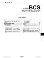
Wiring Diagram - ELECTRONICALLY CONTROLLED POWER STEERING SYSTEM -
INFOID:0000000007329010
ABGWA0024GB
Revision: July 2011 2012 Versa
STC-22
< ECU DIAGNOSIS INFORMATION >
[EPS]
EPS CONTROL UNIT
Fail-Safe
INFOID:0000000007329011
• If any malfunction occurs in the system, and control unit detects the malfunction, EPS warning lamp on com-
bination meter turns ON to indicate system malfunction.
• When EPS warning lamp is ON, enters into a manual steering state. (Control turning force steering wheel
becomes heavy.)
AAGWA0010GB
Revision: July 2011 2012 Versa
EPS CONTROL UNIT
STC-23
< ECU DIAGNOSIS INFORMATION >
[EPS]
C
D
E
F
H
I
J
K
L
M
A
B
STC
N
O
P
DTC Inspection Priority Chart INFOID:0000000007329012
When multiple DTCs are detected simultaneously, check one by one depending on the following priority list.
DTC Index INFOID:0000000007329013
Priority Priority order item (DTC)
1 U1000 CAN COMM CIRCUIT
2 C1601 BATTERY POWER SUPPLY
3 Other than the above
DTC Items (CONSULT screen terms) Reference
C1601 BATTERY VOLT STC-8, "
DTC Logic"
C1604 TORQUE SENSOR STC-10, "DTC Logic"
C1606 EPS MOTOR STC-12, "DTC Logic"
C1607 EEPROM STC-14, "DTC Logic"
C1608 CONTROL UNIT STC-14, "DTC Logic"
C1609 CAN VHCL SPEED STC-15, "DTC Logic"
C1610 CAN ENG RPM STC-16, "DTC Logic"
U1000 CAN COMM CIRCUIT STC-17, "DTC Logic"
Revision: July 2011 2012 Versa
STC-24
< SYMPTOM DIAGNOSIS >
[EPS]
EPS WARNING LAMP DOES NOT TURN ON
SYMPTOM DIAGNOSIS
EPS WARNING LAMP DOES NOT TURN ON
Description INFOID:0000000007329014
EPS warning lamp does not turn ON when turning ignition switch ON from OFF. (Check the illumination of the
EPS warning lamp.)
Diagnosis Procedure INFOID:0000000007329015
1.CHECK EPS WARNING LAMP
Perform the trouble diagnosis of EPS warning Lamp. Refer to STC-18, "
Diagnosis Procedure".
Is the inspection result normal?
YES >> Check that there is no malfunction in each harness connector pin terminal or disconnection.
NO >> Repair or replace the specific malfunctioning part.
Revision: July 2011 2012 Versa
EPS WARNING LAMP DOES NOT TURN OFF
STC-25
< SYMPTOM DIAGNOSIS >
[EPS]
C
D
E
F
H
I
J
K
L
M
A
B
STC
N
O
P
EPS WARNING LAMP DOES NOT TURN OFF
Description INFOID:0000000007329016
EPS warning lamp does not turn OFF several seconds after engine started.
Diagnosis Procedure INFOID:0000000007329017
1.PERFORM SELF-DIAGNOSIS
With CONSULT
1. Turn the ignition switch OFF to ON.
2. Perform EPS control unit self-diagnosis.
Is any DTC detected?
YES >> Check the DTC. Refer to STC-23, "DTC Index".
NO >> GO TO 2.
2.CHECK EPS WARNING LAMP
Perform the trouble diagnosis of EPS warning Lamp. Refer to STC-18, "
Diagnosis Procedure".
Is the inspection result normal?
YES >> GO TO 3.
NO >> Repair or replace the specific malfunctioning part.
3.CHECK EPS CONTROL UNIT POWER SUPPLY AND GROUND CIRCUIT
Perform the trouble diagnosis of EPS control unit power supply and ground. Refer to STC-8, "
Diagnosis Pro-
cedure".
Is the inspection result normal?
YES >> Check that there is no malfunction in each harness connector pin terminal or disconnection.
NO >> Repair or replace the specific malfunctioning part.
Revision: July 2011 2012 Versa