ACS hệ THỐNG điều KHIỂN tốc độ TRÊN INFINITI FX35, FX45 2003
Bạn đang xem bản rút gọn của tài liệu. Xem và tải ngay bản đầy đủ của tài liệu tại đây (2.84 MB, 74 trang )
ACS-1
AUTO CRUISE CONTROL SYSTEM
K ELECTRICAL
CONTENTS
C
D
E
F
G
H
I
J
L
M
SECTION ACS
A
B
ACS
Revision; 2004 April 2003 FX
AUTO CRUISE CONTROL SYSTEM
ASCD
AUTOMATIC SPEED CONTROL DEVICE (ASCD) 3
Description 3
ICC
PRECAUTIONS 4
Precautions for Supplemental Restraint System
(SRS) “AIR BAG” and “SEAT BELT PRE-TEN-
SIONER” 4
Precautions for ICC System Service 4
Wiring Diagrams and Trouble Diagnosis 4
PREPARATION 5
Special Service Tools 5
DESCRIPTION 6
Outline 6
VEHICLE-TO-VEHICLE DISTANCE CONTROL
MODE 6
CONVENTIONAL (FIXED SPEED) CRUISE
CONTROL MODE 6
BRAKE ASSIST (WITH PREVIEW FUNCTION) 6
System Diagram 6
Components Description 7
CAN Communication 7
CAN COMMUNICATION UNIT FOR 2WD
MODEL 7
CAN COMMUNICATION UNIT FOR AWD MOD-
ELS 11
Switch Operation 16
ICC System Display 16
ACTION TEST 17
ICC System Running Test 17
VEHICLE-TO-VEHICLE DISTANCE CONTROL
MODE 17
CONVENTIONAL (FIXED SPEED) CRUISE
CONTROL MODE 18
LASER BEAM AIMING ADJUSTMENT 20
Outline 20
Preparation 20
Outline of Adjustment Procedure 20
Setting the ICC Target Board 20
ADJUSTING HEIGHT OF THE TARGET 20
ADJUSTING THE RIGHT-LEFT POSITION OF
THE TARGET 21
SETTING THE TARGET 21
Aiming Adjustment 22
CHECK AFTER THE ADJUSTMENT 25
ELECTRICAL UNITS LOCATION 26
Component Parts and Harness Connector Location 26
WIRING DIAGRAM 27
Schematic 27
Wiring Diagram — ICC — 28
TERMINALS AND REFERENCE VALUE 35
Terminals and Reference Value for ICC Unit 35
Terminals and Reference Value for ICC Sensor 36
TROUBLE DIAGNOSIS — GENERAL DESCRIP-
TION 37
Work Flow 37
CONSULT-II Function 38
DESCRIPTION 38
CONSULT-II INSPECTION PROCEDURE 38
WORK SUPPORT 39
SELF-DIAGNOSTIC RESULTS 39
DATA MONITOR 40
ACTIVE TEST 41
Self-Diagnostic Function 43
WITH CONSULT-II 43
WITHOUT CONSULT-II 43
SELF-DIAGNOSIS BY ICC SYSTEM DISPLAY
WILL NOT RUN. 44
TROUBLE DIAGNOSIS FOR SELF-DIAGNOSTIC
ITEMS 47
Diagnostic Trouble Code (DTC) Chart 47
DTC 11 CONTROL UNIT 48
DTC 20 CAN COMM CIRCUIT 48
DTC 31 POWER SUPPLY CIR 1, DTC 34 POWER
SUPPLY CIR 2 49
DTC 41 VHCL SPEED SE CIRC 49
DTC 43 VDC/TCS/ABS CIRC 50
DTC 45 BRAKE SW/STOP L SW 50
ACS-2
Revision; 2004 April 2003 FX
DTC 46 OPERATION SW CIRC 52
DTC 61 PRESS SEN CIRCUIT 53
DTC 62 BOOSTER SOL/V CIRCUIT 54
DTC 63 RELEASE SW CIRCUIT 55
DTC 65 PRESSURE CONTROL 56
DTC 74 LASER BEAM OFF CNTR 56
DTC 90 STOP LAMP RLY FIX 57
DTC 92 ECM CIRCUIT 61
DTC 96 NP RANGE 62
DTC 97 AT CIRCUIT 63
DTC 98 GEAR POSITION 63
DTC 102 RADAR STAIN 64
DTC 103 LASER SENSOR FAIL 65
DTC 104 LASER AIMING INCMP 65
DTC 107 LASER COMM FAIL 65
DTC 109 LASER HIGH TEMP 65
TROUBLE DIAGNOSIS FOR SYMPTOMS 66
Symptom Chart 66
Symptom 1: ON/OFF Switch Does Not Switch ON*
1
, ON/OFF Switch Does Not Switch OFF*
2
67
Symptom 2: The ICC System Cannot Be Set (ON/
OFF Switch Turns On/Off). 67
Symptom 3: The ICC System Cannot Be Operated
by the CANCEL Switch, ACCEL/RES Switch, or
DISTANCE Switch 68
Symptom 4: The ICC System Is Not Cancelled
When the Gear Is in Other Than ‘D’ 69
Symptom 5: Chime Does Not Sound 69
Symptom 6: Driving Force Is Hunting 70
Symptom 7: The ICC System Frequently Cannot
Detect the Vehicle Ahead/The Detection Zone Is
Short 70
Symptom 8: The System Does Not Detect the Vehi-
cle Ahead at All 70
ELECTRICAL COMPONENT INSPECTION 72
ICC Steering Switch 72
ICC Brake Switch and Stop Lamp Switch 72
Booster Solenoid 72
Release Switch 73
REMOVAL AND INSTALLATION 74
ICC Unit 74
ICC Sensor 74
ICC Steering Switch 74
AUTOMATIC SPEED CONTROL DEVICE (ASCD)
ACS-3
[ASCD]
C
D
E
F
G
H
I
J
L
M
A
B
ACS
Revision; 2004 April 2003 FX
[ASCD]
AUTOMATIC SPEED CONTROL DEVICE (ASCD) PFP:18930
Description AKS007XN
Regarding the information for ASCD system, refer to EC-657, "AUTOMATIC SPEED CONTROL DEVICE
(ASCD)" (VQ35DE), EC-1329, "AUTOMATIC SPEED CONTROL DEVICE (ASCD)" (VK45DE).
ACS-4
[ICC]
PRECAUTIONS
Revision; 2004 April 2003 FX
[ICC]
PRECAUTIONS PFP:00001
Precautions for Supplemental Restraint System (SRS) “AIR BAG” and “SEAT
BELT PRE-TENSIONER”
AKS007IE
The Supplemental Restraint System such as “AIR BAG” and “SEAT BELT PRE-TENSIONER”, used along
with a front seat belt, helps to reduce the risk or severity of injury to the driver and front passenger for certain
types of collision. This system includes seat belt switch inputs and dual stage front air bag modules. The SRS
system uses the seat belt switches to determine the front air bag deployment, and may only deploy one front
air bag, depending on the severity of a collision and whether the front occupants are belted or unbelted.
Information necessary to service the system safely is included in the SRS and SB section of this Service Man-
ual.
WARNING:
● To avoid rendering the SRS inoperative, which could increase the risk of personal injury or death
in the event of a collision which would result in air bag inflation, all maintenance must be per-
formed by an authorized NISSAN/INFINITI dealer.
● Improper maintenance, including incorrect removal and installation of the SRS, can lead to per-
sonal injury caused by unintentional activation of the system. For removal of Spiral Cable and Air
Bag Module, see the SRS section.
● Do not use electrical test equipment on any circuit related to the SRS unless instructed to in this
Service Manual. SRS wiring harnesses can be identified by yellow and/or orange harnesses or
harness connectors.
Precautions for ICC System Service AKS006Y8
● Do not look straight into the laser beam discharger when adjusting laser beam aiming.
● Turn the ON/OFF switch OFF in conditions similar to driving, suchlike Free rollers or Chassis dynamome-
ter.
● Do not use the ICC sensor removing from vehicle, disassemble, or remodel the sensor.
● Erase DTC when replacing parts of ICC system, then check the operation of ICC system after adjusting
laser beam aiming if necessary.
Wiring Diagrams and Trouble Diagnosis AKS006Y9
When you read wiring diagrams, refer to the followings:
● Refer to GI-15, "How to Read Wiring Diagrams" in GI section
● Refer to PG-3, "POWER SUPPLY ROUTING CIRCUIT" for power distribution circuit in PG section
When you perform trouble diagnosis, refer to the followings:
● Refer to GI-11, "HOW TO FOLLOW TEST GROUPS IN TROUBLE DIAGNOSES" in GI section
● Refer to GI-27, "How to Perform Efficient Diagnosis for an Electrical Incident" in GI section
PREPARATION
ACS-5
[ICC]
C
D
E
F
G
H
I
J
L
M
A
B
ACS
Revision; 2004 April 2003 FX
PREPARATION PFP:00002
Special Service Tools AKS006YA
The actual shapes of Kent-Moore tools may differ from those of special service tools illustrated here.
Tool number
(Kent-Moore No.)
Tool name
Description
KV99110100
(J-45718)
ICC target board
Laser beam aiming adjustment
PKIA0358J
ACS-6
[ICC]
DESCRIPTION
Revision; 2004 April 2003 FX
DESCRIPTION PFP:00000
Outline AKS006YB
The Intelligent Cruise Control (ICC) system automatically maintains a selected distance from the vehicle
ahead according to that vehicle's speed, or at the set speed, if the road ahead is clear.
The ICC function has two cruise control modes and brake assist (with preview function).
VEHICLE-TO-VEHICLE DISTANCE CONTROL MODE
Vehicle-to-vehicle distance control mode, the same speed as other vehicles can be maintained without the
constant need to adjust the operating speed as with a normal cruise control system.
The system is intended to enhance the operation of the vehicle when following another vehicle in the same
lane and direction.
If the distance sensor detects a slower moving vehicle ahead, the system will reduce speed so that the vehicle
ahead can be followed at the selected distance.
The system automatically controls the throttle and applies the brakes (up to 25% of vehicle braking power) if
necessary.
The detection range of the sensor is approximately 390 ft (120 m) ahead.
CONVENTIONAL (FIXED SPEED) CRUISE CONTROL MODE
Conventional (fixed speed) cruise control mode is cruising at preset speeds.
BRAKE ASSIST (WITH PREVIEW FUNCTION)
When the force applied to brake pedal exceeds a certain level, the Brake Assist is activated and generates a
greater braking force than that of a conventional brake booster even with light pedal force.
When the Preview Function identifies the need to apply the sudden brake by sensing the vehicle ahead in the
same lane and the distance and relative speed from it, it applies the brake pre-pressure before driver depress
the brake pedal and improves brake response by reducing its free play.
Refer to Owner's Manual for Intelligent Cruise Control System operating instructions.
System Diagram AKS006YC
SKIA5972E
DESCRIPTION
ACS-7
[ICC]
C
D
E
F
G
H
I
J
L
M
A
B
ACS
Revision; 2004 April 2003 FX
Components Description AKS006YD
CAN Communication AKS00815
CAN (Controller Area Network) is a serial communication line for real time application. It is an on-vehicle mul-
tiplex communication line with high data communication speed and excellent error detection ability. Many elec-
tric control units are equipped onto a vehicle, and each control unit shares information and links with other
control units during operation (not independent). In CAN communication, control units are connected with 2
communication lines (CAN H line, CAN L line) allowing a high rate of information transmission with less wiring.
Each control unit transmits/receives data but selectively reads required data only.
CAN COMMUNICATION UNIT FOR 2WD MODEL
System Diagram
Component
Vehicle-
to-vehi-
cle dis-
tance
control
mode
Conven-
tional
(fixed
speed)
cruise
control
mode
Brake
assist
(with
preview
brake)
Description
ICC unit ×××
Operates throttle control actuator and brake booster based on that sen-
sor signals and CAN communication data, then controls vehicle distance.
ICC sensor ××
Irradiate laser beam, and receives reflected laser beam to measure dis-
tance from preceding vehicle.
ECM ××
Transmits throttle position signal and ICC steering switch signal to ICC
unit.
ABS actuator and electric
unit (control unit)
×××Transmits wheel speed signal to ICC unit.
Brake pressure sensor ××Detects fluid pressure in master cylinder.
Brake booster ××Adjusts brake fluid pressure, based on command from ICC unit.
BCM × Transmit front wiper request signal to ICC unit.
TCM ××
Transmits gear position signal and output shaft revolution signal to ICC
unit.
SKIA6173E
ACS-8
[ICC]
DESCRIPTION
Revision; 2004 April 2003 FX
Input/output Signal Chart
T: Transmit R: Receive
Signals ECM TCM
Dis-
play
con-
trol
unit
Low
tire
pres-
sure
warn-
ing
con-
trol
unit
ICC
unit
Intelli-
gent
Key
unit
BCM
Steeri
ng
angle
sen-
sor
Uni-
fied
meter
and
A/C
amp.
ICC
sen-
sor
ABS
actu-
ator
and
elec-
tric
unit
(con-
trol
unit)
Driver
seat
con-
trol
unit
IPDM
E/R
Engine speed signal T R R R R R
Engine status signal T R
Engine coolant tempera-
ture signal
TR R R
A/T self-diagnosis signal R T
Accelerator pedal posi-
tion signal
TR R R
Closed throttle position
signal
TR R
Wide open throttle posi-
tion signal
TR
Battery voltage signal T R
Key switch signal T R
Ignition switch signal T R R
P range signal T R R R
Stop lamp switch signal R T
ABS operation signal R R T
TCS operation signal R R T
VDC operation signal R R T
Fuel consumption moni-
tor signal
TR R
Input shaft revolution sig-
nal
RT R
Output shaft revolution
signal
RT R
A/C switch signal R T
A/C compressor request
signal
T R
A/C relay status signal R T
A/C compressor feed-
back signal
TR
Blower fan motor switch
signal
RT
A/C control signal
TR
RT
Cooling fan speed signal R T
Position light request sig-
nal
RTRR
Low beam request signal T R
Low beam status signal R T
DESCRIPTION
ACS-9
[ICC]
C
D
E
F
G
H
I
J
L
M
A
B
ACS
Revision; 2004 April 2003 FX
High beam request sig-
nal
TR R
High beam status signal R T
Front fog light request
signal
TR
Day time running light
request signal
TR
Turn LED burnout status
signal
RT
Vehicle speed signal
RRT
RRRR RR TR R
Sleep wake up signal
TR RR
TR
Door switch signal R R T R R R
Turn indicator signal T R
Key fob ID signal T R
Key fob door unlock sig-
nal
TR
Oil pressure switch sig-
nal
RT
TR
Buzzer output signal
TR
TR
TR
Fuel level sensor signal R T
Fuel level low warning
signal
RT
ICC operation signal R T
Front wiper request sig-
nal
RT R
Front wiper stop position
signal
RT
Rear window defogger
switch signal
TR
Rear window defogger
control signal
RR R T
Hood switch signal R T
Theft warning horn
request signal
TR
Horn chirp signal T R
Steering angle sensor
signal
TR
Tire pressure signal T R
Signals ECM TCM
Dis-
play
con-
trol
unit
Low
tire
pres-
sure
warn-
ing
con-
trol
unit
ICC
unit
Intelli-
gent
Key
unit
BCM
Steeri
ng
angle
sen-
sor
Uni-
fied
meter
and
A/C
amp.
ICC
sen-
sor
ABS
actu-
ator
and
elec-
tric
unit
(con-
trol
unit)
Driver
seat
con-
trol
unit
IPDM
E/R
ACS-10
[ICC]
DESCRIPTION
Revision; 2004 April 2003 FX
Tire pressure data signal R T
ABS warning lamp signal R R T
VDC OFF indicator lamp
signal
RRT
SLIP indicator lamp sig-
nal
RT
Brake warning lamp sig-
nal
RT
System setting signal T R R
Distance to empty signal R T
Hand brake switch signal R T
Door lock/unlock request
signal
TR
Door lock/unlock status
signal
RT
Starter permission signal T R
Back door open request
signal
TR
Power window open
request signal
TR
Alarm request signal T R
Key warning signal T R
ICC sensor signal R T
ICC warning lamp signal T R
ICC system display sig-
nal
TR
Current gear position sig-
nal
TR R
Steering switch signal T R
ASCD operation signal T R
ASCD OD cancel
request
TR
ICC OD cancel request R R T
A/T CHECK indicator
lamp signal
TR
A/T position indicator
lamp signal
TR
A/T shift schedule
change demand signal
R T
Manual mode signal R T
Not manual mode signal R T
Manual mode shift up
signal
RT
Signals ECM TCM
Dis-
play
con-
trol
unit
Low
tire
pres-
sure
warn-
ing
con-
trol
unit
ICC
unit
Intelli-
gent
Key
unit
BCM
Steeri
ng
angle
sen-
sor
Uni-
fied
meter
and
A/C
amp.
ICC
sen-
sor
ABS
actu-
ator
and
elec-
tric
unit
(con-
trol
unit)
Driver
seat
con-
trol
unit
IPDM
E/R
DESCRIPTION
ACS-11
[ICC]
C
D
E
F
G
H
I
J
L
M
A
B
ACS
Revision; 2004 April 2003 FX
CAN COMMUNICATION UNIT FOR AWD MODELS
System Diagram
Manual mode shift down
signal
RT
Manual mode indicator
signal
TR R
Ignition knob switch sig-
nal
TR
Signals ECM TCM
Dis-
play
con-
trol
unit
Low
tire
pres-
sure
warn-
ing
con-
trol
unit
ICC
unit
Intelli-
gent
Key
unit
BCM
Steeri
ng
angle
sen-
sor
Uni-
fied
meter
and
A/C
amp.
ICC
sen-
sor
ABS
actu-
ator
and
elec-
tric
unit
(con-
trol
unit)
Driver
seat
con-
trol
unit
IPDM
E/R
SKIA6176E
ACS-12
[ICC]
DESCRIPTION
Revision; 2004 April 2003 FX
Input/output Signal Chart
T: Transmit R: Receive
Signals ECM TCM
Dis-
play
con-
trol
unit
Low
tire
pres-
sure
warn-
ing
con-
trol
unit
AWD
con-
trol
unit
ICC
unit
Intel-
ligent
Key
unit
BCM
Steer
ing
angle
sen-
sor
Uni-
fied
mete
r and
A/C
amp.
ICC
sen-
sor
ABS
actu-
ator
and
elec-
tric
unit
(con-
trol
unit)
Drive
r
seat
con-
trol
unit
IPDM
E/R
A/T self-diagnosis sig-
nal
RT
ABS operation signal R R R T
TCS operation signal R R T
VDC operation signal R R R R T
Stop lamp switch sig-
nal
RR T
Battery voltage signal T R
Key switch signal T R
Ignition switch signal T R R
P range signal T R R R
Closed throttle posi-
tion signal
TR R
Wide open throttle
position signal
TR
Engine speed signal T R R R R R R
Engine status signal T R
Engine coolant tem-
perature signal
TRRR
Accelerator pedal
position signal
TR RR R
Fuel consumption
monitor signal
TR R
A/T self-diagnosis sig-
nal
RT
Input shaft revolution
signal
RT R
Output shaft revolution
signal
RT R
A/C switch signal R T
A/C compressor
request signal
T R
A/C relay status signal R T
A/C compressor feed-
back signal
TR
Blower fan motor
switch signal
RT
A/C control signal
TR
RT
Cooling fan speed sig-
nal
R T
DESCRIPTION
ACS-13
[ICC]
C
D
E
F
G
H
I
J
L
M
A
B
ACS
Revision; 2004 April 2003 FX
Position light request
signal
RTRR
Low beam request
signal
TR
Low beam status sig-
nal
R T
High beam request
signal
TR R
High beam status sig-
nal
R T
Front fog light request
signal
TR
Day time running light
request signal
TR
Turn LED burnout sta-
tus signal
RT
Vehicle speed signal
RRT
RRRR RR TR R
Sleep wake up signal
TR RR
TR
Door switch signal R R T R R R
Key fob ID signal T R
Key fob door unlock
signal
TR
Oil pressure switch
signal
RT
TR
Buzzer output signal
TR
TR
TR
Fuel level sensor sig-
nal
RT
Fuel level low warning
signal
RT
ICC operation signal R T
Front wiper request
signal
RT R
Front wiper stop posi-
tion signal
RT
Rear window defogger
switch signal
TR
Rear window defogger
control signal
RR R T
Hood switch signal R T
Signals ECM TCM
Dis-
play
con-
trol
unit
Low
tire
pres-
sure
warn-
ing
con-
trol
unit
AWD
con-
trol
unit
ICC
unit
Intel-
ligent
Key
unit
BCM
Steer
ing
angle
sen-
sor
Uni-
fied
mete
r and
A/C
amp.
ICC
sen-
sor
ABS
actu-
ator
and
elec-
tric
unit
(con-
trol
unit)
Drive
r
seat
con-
trol
unit
IPDM
E/R
ACS-14
[ICC]
DESCRIPTION
Revision; 2004 April 2003 FX
Theft warning horn
request signal
TR
Horn chirp signal T R
Steering angle sensor
signal
TR
Tire pressure signal T R
Tire pressure data sig-
nal
RT
ABS warning lamp
signal
RRT
VDC OFF indicator
lamp signal
RRT
SLIP indicator lamp
signal
RT
Brake warning lamp
signal
RT
System setting signal T R R
AWD warning lamp
signal
TR
AWD lock indicator
lamp signal
TR
Distance to empty sig-
nal
RT
Hand brake switch
signal
RRT
Door lock/unlock
request signal
TR
Door lock/unlock sta-
tus signal
RT
Starter permission sig-
nal
TR
Back door open
request signal
TR
Power window open
request signal
TR
Alarm request signal T R
Key warning signal T R
ICC sensor signal R T
ICC warning lamp sig-
nal
TR
ICC system display
signal
TR
Current gear position
signal
TR R
Signals ECM TCM
Dis-
play
con-
trol
unit
Low
tire
pres-
sure
warn-
ing
con-
trol
unit
AWD
con-
trol
unit
ICC
unit
Intel-
ligent
Key
unit
BCM
Steer
ing
angle
sen-
sor
Uni-
fied
mete
r and
A/C
amp.
ICC
sen-
sor
ABS
actu-
ator
and
elec-
tric
unit
(con-
trol
unit)
Drive
r
seat
con-
trol
unit
IPDM
E/R
DESCRIPTION
ACS-15
[ICC]
C
D
E
F
G
H
I
J
L
M
A
B
ACS
Revision; 2004 April 2003 FX
Steering switch signal T R
ASCD operation sig-
nal
TR
ASCD OD cancel
request
TR
ICC OD cancel
request
RR T
A/T CHECK indicator
lamp signal
TR
A/T position indicator
lamp signal
TR
A/T shift schedule
change demand signal
R T
Manual mode signal R T
Not manual mode sig-
nal
RT
Manual mode shift up
signal
RT
Manual mode shift
down signal
RT
Manual mode indica-
tor signal
TR
Ignition knob switch
signal
TR
Signals ECM TCM
Dis-
play
con-
trol
unit
Low
tire
pres-
sure
warn-
ing
con-
trol
unit
AWD
con-
trol
unit
ICC
unit
Intel-
ligent
Key
unit
BCM
Steer
ing
angle
sen-
sor
Uni-
fied
mete
r and
A/C
amp.
ICC
sen-
sor
ABS
actu-
ator
and
elec-
tric
unit
(con-
trol
unit)
Drive
r
seat
con-
trol
unit
IPDM
E/R
ACS-16
[ICC]
DESCRIPTION
Revision; 2004 April 2003 FX
Switch Operation AKS006YF
The system is operated by a master ON/OFF switch and four control switches, all mounted on the steering
wheel.
ICC System Display AKS006YG
SKIA5973E
No. Switch name Description
1 ACCEL/RES switch Resumes set speed or increases speed incrementally
2 COAST/SET switch Sets desired cruise speed, reduces speed incrementally
3 ON/OFF switch Master switch to activate the system
4 CANCEL switch Deactivates system without erasing set speed
5 DISTANCE switch Changes the following distance from: Long, Middle, Short
SKIA6177E
No. Component Description
1 Set vehicle speed indicator Indicates the set vehicle speed.
2 Vehicle ahead detection indicator Indicates whether it detects a vehicle ahead.
3 Set distance indicator Display the selected distance between vehicles set with the DISTANCE switch.
4 Own vehicle indicator Indicates the base vehicle.
5 ON/OFF switch indicator lamp (Green) Indicates that the ON/OFF switch is ON.
6
Intelligent cruise control system warning
lamp (Yellow)
The light comes on if there is a malfunction in the ICC system.
7 Cruise set switch indicator lamp Indicates that the conventional cruise control mode is controlled.
ACTION TEST
ACS-17
[ICC]
C
D
E
F
G
H
I
J
L
M
A
B
ACS
Revision; 2004 April 2003 FX
ACTION TEST PFP:00000
ICC System Running Test AKS006YH
VEHICLE-TO-VEHICLE DISTANCE CONTROL MODE
Set Checking
1. Press the ON/OFF switch for less than 1.5 seconds.
2. Drive the vehicle between 25 MPH (40 km/h for CANADA models) and 90 MPH (144 km/h for CANADA
models).
3. Push the COAST/SET switch.
4. Confirm that the desired speed is set as hand is released from the COAST/SET switch.
NOTE:
● When there is no vehicle ahead, drive at the set speed steadily.
● When there is a vehicle ahead, control to maintain distance from the vehicle ahead, watching its speed.
● The set vehicle speed is displayed on the ICC system indicator in the combination meters.
Check for Increase of the Cruising Speed
1. Set vehicle-to-vehicle distance control mode at desired speed.
2. Check if the set speed increases by 1 MPH (1 km/h for CANADA models) as ACCEL/RES switch is
pushed.
NOTE:
The maximum set speed of the vehicle-to-vehicle distance control mode is 90 MPH (144 km/h for CANADA
models).
Check for Decrease of the Cruising Speed
1. Set vehicle-to-vehicle distance control mode at desired speed.
2. Check if the set speed decreases by 1 MPH (1 km/h for CANADA models) as COAST/SET switch is
pushed.
NOTE:
● Vehicle-to-vehicle distance control mode is automatically turned off when the driving speed lowers to 20
MPH (32 km/h for CANADA models) due to the deceleration of the vehicle ahead.
● The minimum set speed of the vehicle-to-vehicle distance control mode is 25 MPH (40 km/h for CANADA
models).
Check for the Cancellation of Vehicle-to-Vehicle Distance Control Mode (Normal Driving Con-
dition) in the Following Cases:
1. When the brake pedal is depressed after the system is turned on.
2. When the select lever is shifted into other than “D” including manual shift.
3. When the ON/OFF switch is turned off.
4. When CANCEL switch is operated.
Check for Restoring the Speed that is Set by Vehicle-to-Vehicle Distance Control Mode Before
Cancellation
1. Cancel the system by depressing the foot brake.Then, check that the speed before cancellation is
restored when pressing ACCEL/RES switch with 25 MPH (40 km/h for CANADA models) or above.
2. Cancel the system by shifting the select lever into other than “D”, Then, check if the speed set before the
cancellation is restored when ACCEL/RES switch is pressed.
3. Check if the speed previously set is restored when ACCEL/RES switch is operated with driving 25 MPH
(40 km/h for CANADA models), after canceling vehicle-to-vehicle distance control mode by operating the
CANCEL switch.
ACS-18
[ICC]
ACTION TEST
Revision; 2004 April 2003 FX
Check for On/Off Switch
1. Start the engine.Then, check the following operations are car-
ried correctly.
2. Vehicle-to-vehicle distance control mode is displayed in speed-
ometer illuminates when ON/OFF switch is pressed “ON” for
less than 1.5 seconds and ready for operation.The illumination
goes off when ON/OFF switch is turned to OFF.
3. “CRUISE” illumination and ICC system display go off when the
key switch is turned to OFF while ON/OFF switch is ON
(“CRUISE” illumination is ON and vehicle-to-vehicle distance
control mode is ready for operation).
Check for Accel-res, Coast-set, Cancel Switches
1. Check if ACCEL/RES, COAST/SET, CANCEL switches are operated smoothly.
2. Check if buttons come up as hand is released from the buttons.
Check for Distance Switch
1. Start the engine.
2. Press the ON/OFF switch for less than 1.5 seconds.
3. Press the DISTANCE switch.
4. Check if the set distance indicator changes display in order of:
(long)→(middle)→(short).
NOTE:
The set distance indicator shows 'long' immediately after the engine starts.
CONVENTIONAL (FIXED SPEED) CRUISE CONTROL MODE
Set Checking
1. Press the ON/OFF switch for more than 1.5 seconds.
2. Drive the vehicle between 25 MPH (40 km/h for CANADA models) and 90 MPH (144 km/h for CANADA
models).
3. Push the COAST/SET switch.
4. Confirm that the desired speed is set as hand is released from the COAST/SET switch.
NOTE:
● ICC system display in the combination meters shows nothing.
SKIA6189E
SKIA6178E
ACTION TEST
ACS-19
[ICC]
C
D
E
F
G
H
I
J
L
M
A
B
ACS
Revision; 2004 April 2003 FX
Check for Increase of the Cruising Speed
1. Set the conventional (fixed speed) cruise control mode at desired speed.
2. Check if the set speed increases by 1 MPH (1.6 km/h for CANADA models) as ACCEL/RES switch is
pushed.
NOTE:
● If the ACCEL/RES switch is kept lifting up during cruise control driving, the vehicle speed increases until
the switch is released.
● The maximum set speed is 90 MPH (144 km/h for CANADA models).
Check for Decrease of the Cruising Speed
1. Set the conventional (fixed speed) cruise control mode at desired speed.
2. Check if the set speed decreases by 1 MPH (1.6 km/h for CANADA models) as COAST/SET switch is
pushed.
NOTE:
● Conventional (fixed speed) cruise control mode is automatically turned off when the driving speed lowers
to 20 MPH (32 km/h for CANADA models) due to the deceleration of the vehicle ahead.
● The lowest set speed is 25 MPH (40 km/h for CANADA models).
Check for the Cancellation of Conventional (Fixed Speed) Cruise Control Mode (Normal Driv-
ing Condition) in the Following Cases:
Refer to ACS-17, "Check for the Cancellation of Vehicle-to-Vehicle Distance Control Mode (Normal Driving
Condition) in the Following Cases:" .
Check for restoring the Speed that is Set By Conventional (Fixed Speed) Cruise Control Mode
Before ICC Cancellation
Refer to ACS-17, "Check for Restoring the Speed that is Set by Vehicle-to-Vehicle Distance Control Mode
Before Cancellation" .
Check for On/Off Switch
1. Start the engine.Then, check the following operations are car-
ried correctly.
2. “CRUISE” lamp (green) illuminates and ICC system indicator
goes off when ON/OFF switch is pressed “ON” for more than 1.5
seconds, and then ready for operation. The illumination goes off
when ON/OFF switch is turned to OFF.
3. “CRUISE” illumination go off when the key switch is turned to
OFF while ON/OFF switch is ON.
Check for Accel/Res, Coast/Set Cancel Switches
1. Check if ACCEL/RES, COAST/SET, CANCEL switches are operated smoothly.
2. Check if buttons come up as hand is released from the buttons.
SKIA6188E
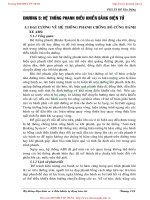
ACS-20
[ICC]
LASER BEAM AIMING ADJUSTMENT
Revision; 2004 April 2003 FX
LASER BEAM AIMING ADJUSTMENT PFP:00026
Outline AKS006YI
Adjust the laser beam aiming every time the ICC sensor is removed or installed.
CAUTION:
● Place the vehicle on the level ground when the laser beam aiming adjustment is operated.
● Follow the CONSULT-II when adjusting the Laser beam aiming (Laser beam aiming adjustment
cannot be operated without CONSULT-II).
Preparation AKS006YJ
● Keep all tires inflated to correct pressures. Adjust the tire pressure to the specified pressure value.
● See that there is no-load in vehicle other than the driver (or equivalent weight placed in driver's position).
Coolant, engine oil filled up to correct level and full fuel tank.
● Shift the gear into “P” position and release the parking brake.
● Clean the sensor with a soft cloth.
Outline of Adjustment Procedure AKS006YK
1. Set up the ICC target board [KV99110100 (J-45718)].
2. Adjust the sensor following the procedure on CONSULT-II (Turn manually the screw for up-down position
adjustment. ICC sensor automatically adjust the right-left position.).
Setting the ICC Target Board AKS006YL
Accurate ICC target board setting is required for the laser beam aiming adjustment.
CAUTION:
ICC system does not function normally if laser beam aiming is not accurate.
ADJUSTING HEIGHT OF THE TARGET
1. Attach a triangle scale as shown in the right figure.
SKIA6179E
SKIA5974E
LASER BEAM AIMING ADJUSTMENT
ACS-21
[ICC]
C
D
E
F
G
H
I
J
L
M
A
B
ACS
Revision; 2004 April 2003 FX
2. Adjust the height of the target stand so that the point of the trian-
gle aims the center of the ICC sensor.
ADJUSTING THE RIGHT-LEFT POSITION OF THE TARGET
1. Attach a scale (at least 350 mm [14 in] or longer) or stick as
shown in the figure.
2. Suspend a thread with weight on the tip of the thread to 310 mm
(12.2 in) left side of the target board from the center of the tar-
get board on top.
SETTING THE TARGET
1. Suspend a thread with weight on tip to splice the center of the front and back bumpers. Then, mark the
center point on the ground as each weight points.
2. Link the front and back bumpers center points marked on the ground, and mark a point 5 m ahead of the
sensor, on the extended line of the previous link line of the bumper center points. Then, adjust the position
of the target board so that the weight come on the top of the marked point (5 m ahead of the sensor) and
face to the vehicle.
3. Adjust the position of the target board so that the extended line
that links the center of the rear window (the center of the rear
window defogger pattern) and the center of the front windshield
(the setting part of the room mirror) align with the weight sus-
pended from the board.
4. Remove the thread suspended to the left side of board and sus-
pend a thread with weight on tip on the center of the target
board.Then mark the point of weight on the ground.
SKIA6180E
SKIA1211E
SKIA5975E
SKIA1213E
ACS-22
[ICC]
LASER BEAM AIMING ADJUSTMENT
Revision; 2004 April 2003 FX
5. Pivot the edge of the target board 20° to either side.
NOTE:
Approx. 50 mm (1.97 in) shift rates the 20° movement.
6. Do not place anything in the space shown in the figure (view from top).
NOTE:
In case the space shown in the illustration is not available, make space by covering the side of the target
board with a 400 mm (15.75 in)-size frosted black board or black cloth.
Aiming Adjustment AKS006YM
CAUTION:
● Complete all necessary work for laser beam adjustment until the adjustment completes as shown
in the procedure. If the procedure does not complete, the ICC system is inoperable.
● If CONSULT-II is used with no connection of CONSULT-II CONVERTER, malfunctions might be
detected in self-diagnosis depending on control unit which carry out CAN communication.
1. Turn ignition switch OFF.
2. Connect CONSULT-II and CONSULT-II CONVERTER on the
data link connector.
PKIA2589E
SKIA5976E
SKIA1216E
PBIB1503E
LASER BEAM AIMING ADJUSTMENT
ACS-23
[ICC]
C
D
E
F
G
H
I
J
L
M
A
B
ACS
Revision; 2004 April 2003 FX
3. Start the engine, wait for at least 10 sec., and touch “START
(NISSAN BASED VHCL)”.
4. Touch “ICC”.
If “ICC” is not indicated, go to GI-40, "
CONSULT-II Data Link
Connector (DLC) Circuit" .
5. Touch “WORK SUPPORT”.
6. Touch “LASER BEAM ADJUST”.
7. Touch “START”.
CAUTION:
If the adjustment screen does not appear on CONSULT-II 10
sec. after touching “LASER BEAM ADJUST” screen, the fol-
lowing causes may be considered:
● Target is not set accurately.
● There is not enough space beside the target.
● Deformation of vehicle or the surrounding equipment
unit, bracket, or the surrounding equipment is causing
inappropriate installation of sensor and aiming may be
set out of the adjustable range.
SKIA3098E
SKIA6193E
PKIA8867E
SKIA6191E
SKIA1220E
ACS-24
[ICC]
LASER BEAM AIMING ADJUSTMENT
Revision; 2004 April 2003 FX
● The area is not suitable for the adjustment work.
● ICC sensor is not clean.
8. After the CONSULT-II displays “ADJUST THE VERTICAL OF
LASER” turn the up-down direction adjusting screw until “U/D
CORRECT” value is set in the range of ±4.
CAUTION:
Turn the screw slowly. The value change on display is
slower than actual movement of the ICC sensor. Wait for 2
seconds every time the screw is turned half a rotation.
NOTE:
Turning the screw to the right lowers the aiming and to the left
lifts the aiming.
9. When “U/D CORRECT” value indicates ±4, confirm that the margin of value remains within ±4 at least for
2 seconds with no equipment or hand touching the ICC sensor.
When “COMPLETED THE VERTICAL AIMING OF LASER
BEAM” appears on screen, touch “END”.
CAUTION:
Be sure that the margin of “U/D CORRECT” is within ±4 with
ICC sensor unit is untouched.
10. Confirm that “ADJUSTING AUTOMATIC HORIZONTAL LASER
BEAM AIMING” is on screen and wait for a while (maximum: 10
seconds).
SKIA1221E
SKIA6181E
SKIA1223E
SKIA1224E
LASER BEAM AIMING ADJUSTMENT
ACS-25
[ICC]
C
D
E
F
G
H
I
J
L
M
A
B
ACS
Revision; 2004 April 2003 FX
11. Confirm that “NORMALLY COMPLETED” is displayed on CON-
SULT-II and close the aiming adjustment procedure by touching
“END”.
CAUTION:
Complete all the procedures once “LASER BEAM ADJUST”
mode is entered in CONSULT-II. When the procedure is dis-
continued, the ICC system is inoperable.
CHECK AFTER THE ADJUSTMENT
Test the ICC system operation by running test. Refer to ACS-17, "ICC System Running Test" .
SKIA1225E