hướng dẫn test MBA
Bạn đang xem bản rút gọn của tài liệu. Xem và tải ngay bản đầy đủ của tài liệu tại đây (77.02 KB, 10 trang )
11/11/02 Pagina 1 di 10
GUIDE FOR TESTING POWER TRANSFORMERS
Routine test
11/11/02 Pagina 2 di 10
INDEX
Introduction 3
1 Dielectric tests – Separate-source voltage withstand test 4
2 Induced voltage test 5
3 Voltage ratio measurement and check of polarities and connections 6
4 No-load current and no-load loss measurement 7
5 Winding resistance measurement 8
HV winding resistance measurement 8
LV winding resistance measurement 8
6 Short-circuit impedance and load loss measurement 9
7 Partial discharge measurement 10
11/11/02 Pagina 3 di 10
Introduction
The following routine tests must be carried out on all power transformers :
• separate-source voltage withstand test
• induced voltage test
• voltage ratio measurement and check of polarities and connections
• no-load current and no-load loss measurement
• winding resistance measurement
• short-circuit impedance and load loss measurement
• partial discharge measurement
in accordance with the International Basic Standards IEC 60726 for Dry-type power transformers
11/11/02 Pagina 4 di 10
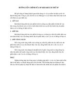
1 Dielectric tests – Separate-source voltage withstand test
The single-phase applied voltage wave shape shall be approximately sinusoidal. The test must be
performed at rated frequency. At the end of the test, the test voltage shall be rapidly reduced up
to 1/3 the full voltage before disconnection. The full test voltage shall be applied for 60 seconds
between the winding under test and all the remaining windings, magnetic core, frame and
enclosure connected to earth. The test shall be performed on all the windings.The test is
successful if no failure occurs at full test voltage.
CONNECTION SCHEME:
G
Generator
Voltmeter
A
Current
transforme
r
Transformer, under test
Amperemeter
HV LV
R
Shunt for current
Example: test of HV
Voltage
Transformer
11/11/02 Pagina 5 di 10
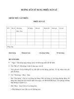
2 Induced voltage test
The test voltage shall be twice the value corresponding to the rated voltage; it shall be applied
between the terminals of the secondary windings, by maintaining the primary winding open. The
duration of the test at full voltage shall be 60 s, and the frequency twice the rated value. The test
shall start with a voltage lower than 1/3 the full test voltage, and it shall be quickly increased up to
full value. At the end of the test, the voltage shall be rapidly reduced up to 1/3 the rated value
before disconnection. The test is successful if no failure occurs at full test voltage.
CONNECTION SCHEME:
G
Generator
100 HZ
Voltmeter and
Ammeter
Current transformer
Voltage transformer
Transformer, under test
LV HV
11/11/02 Pagina 6 di 10
Computer
Transformer, under test
HV LV
Ratiometer
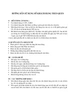
3 Voltage ratio measurement and check of polarities and connections
Voltage ratio measurement and check of polarities and connections shall be performed on all tap-
changer positions; the correspondence between the numbers assigned to the tappings and the
ratings shall also be checked. Voltage ratio measurement shall be performed phase by phase
between the terminals of corresponding windings. Voltage ratio measurement is carried out by
use of potentiometric method.
CONNECTION SCHEME:
11/11/02 Pagina 7 di 10
G
Generat
Watt and Current and voltage
Transducers
Computer
Current transformer
Voltage transformer
Transformer, under test
LV HV
4 No-load current and no-load loss measurement
This test is performed by supplying LV windings at rated frequency and rated voltage. The wave
shape shall be as nearly as possible of the sine-wave and the primary windings shall be open.
The frequency of the test shall not differ from the rated value more than ± 1%. No-load current
and loss shall be measured as well as the mean value and the effective value of the voltage. If
these two readings are equal, no correction shall be applied on the measurement of no-load
loss; otherwise, no-load loss shall be referred to sine-wave condition in accordance with IEC
Standards 60076-1. No-load current shall result as the average value of three readings performed
by effective value ammeters. Three wattmeters shall be used to measure the power, by using
instrument transformers and transducers when necessary.
CONNECTION SCHEME:
11/11/02 Pagina 8 di 10
5 Winding resistance measurement
Winding resistance measurement shall be performed when the windings are at ambient
temperature without supply for a time long enough to achieve this condition. The measurements
shall be carried out in direct current between terminals according to the sequence U-V; V-W; W-
U.
Ambient temperature shall also be measured. It shall result as the average value of three
measurements performed by apposite thermal sensors.
HV winding resistance measurement
HV winding resistance measurement shall be performed by measuring simultaneously voltage
and current. The voltmeter and ammeter must be connected as follows :
• voltmeter terminals must be connected beyond current cables;
• the current shall not exceed 10% of winding rated current;
• the measurement shall be carried out after voltage and current are stable.
Unless otherwise agreed, the HV winding shall be connected on principal tapping.
LV winding resistance measurement
LV winding resistance measurement shall be performed by measuring simultaneously voltage and
current. The voltmeter and ammeter shall be connected as follows :
• voltmeter terminals shall be connected beyond current cables;
• the current shall not exceed 5% of winding rated current;
• the measurement shall be carried out after voltage and current are stable.
CONNECTION SCHEME:
V
Computer
Transformer, under test
HV LV
Current source
V
Voltmet
R
Example: HV-
A
mbient
temperature
11/11/02 Pagina 9 di 10
6 Short-circuit impedance and load loss measurement
Short-circuit impedance and load loss measurement shall be performed at rated frequency, by
applying on the transformer primary windings ( connected on principal tapping) a three –phase
sine-wave voltage system. The secondary windings shall be short-circuited. Applied voltage,
current and load loss shall be measured.
The frequency of the test shall not differ from the rated frequency more than ± 1%. In case the
rated power is higher than 1000 kVA, load loss shall be measured by using three wattmeters, in
order to reduce measurement uncertainties. When necessary, instrument transformers and
transducers shall be used. The measured values shall be referred to rated current and then
calculated at reference temperature. This temperature is the annual average ambient
temperature (20°C) increased by the permissible temperature rise in accordance with the
temperature class of the windings. IEC 60726 specify the permissible temperature rises on table
no. 4. Beside, IEC 60076-1 give a complete explanation of how to perform the carries at rated
current and at reference temperature.
CONNECTION SCHEME:
G
Generat
Watt and Current and Voltage
Transducers
Computer
Current transformer
Voltage transformer
Short circuit
Transformer, under test
HV LV
Ambient
temperature
11/11/02 Pagina 10 di 10
7 Partial discharge measurement
A basic measuring circuit for partial discharge test is shown in figure 2 , IEC Standards 60726.
The low-voltage windings shall be supplied from an alternate 100 Hz voltage source. The voltage
shape shall be as nearly as possible of the sine-wave. Unless otherwise specified, a pre-stress
voltage of 1,5 U
m shall be induced for 30 s, followed without interruption by a voltage of 1,1 Um for
three minutes, during which the partial discharge level shall be measured. The calibration of the
measuring circuit is carried out by injecting simulated discharge pulses of 100pC at transforner
terminals. Partial discharge measurement shall be carried out by use of an oscilloscope, in order
to analise the developing of the ongoing phenomena. Test procedures must be in accordance
with IEC Standards 60726. The test is successful if the partial discharge level is lower than 20 pC
unless otherwise agreed between manufacturer and purchaser.
CONNECTION SCHEME:
G
Generator
100 Hz
Transformer, under test
LV HV
Impedance Z
m
P.D.
Measuring unit
Switch
C
Coupling capacitors
Voltmeter
Partial discharge test
Voltage transformer
Filter
for partial discharge test